1
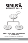
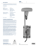
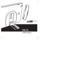
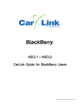
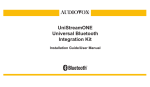
SIRIUS Outdoor Satellite Radio Antenna Installation Manual Thank you for purchasing a SIRIUS Outdoor Satellite Radio Antenna. Your new SIRIUS Outdoor Satellite Radio Antenna is a high-performance antenna, specifically designed to receive signals from the SIRIUS satellites and terrestrial (ground) transmitters when mounted outdoors on a home or other building. This antenna has been approved by Sirius Satellite Radio to receive the SIRIUS signal under a variety of conditions within the SIRIUS North American coverage area. Installation of this antenna requires experience in mechanical and electrical procedures. Review this installation manual before beginning the installation of the antenna. If you are not comfortable or experienced with general installation procedures, SIRIUS recommends that you have a professional install the antenna for you. The antenna should be mounted according to the instructions in this manual to ensure the best quality reception of the SIRIUS signal. All necessary mounting hardware for a variety of mounting options is included with the antenna. Box Contents Open the box and verify that all the items shown below are included with the Outdoor Antenna. If any items are missing, please contact your dealer or retailer immediately. Keep your purchase receipt and the packaging materials should you need to return or ship the antenna. Outdoor Antenna 30 ft. Antenna Cable U-Bolts (2) Mounting Brackets (2) Hex Lock Nuts (4) #10 Screws (4) Installation Manual (not shown) Tools Required A Phillips screwdriver is needed for installation. Depending upon the type of installation, a 3/8 in. wrench and power drill with a 3/32 in. drill bit may also be required. 2 Outdoor Satellite Antenna Installation Manual Caution and Warnings WARNING: Be sure not to cut, damage, or puncture the external jacket of the antenna cable during the installation procedure. Damage to the antenna cable can cause the SIRIUS signal to be degraded or unavailable, and can also cause water to intrude into the antenna cable causing the cable to fail. WARNING: Do not lengthen or shorten the antenna cable by cutting it. Doing so may cause the antenna to not function properly. Purchase the optional antenna cable extension if a longer antenna cable is necessary. Antenna Location For proper operation and best reception of the SIRIUS signal, it is important to locate the antenna in a place where it will be oriented toward the general direction of the SIRIUS satellites, and free of obstructions which would block the antenna’s view of the sky. The SIRIUS satellites follow a fixed orbit over the USA, and, depending upon your location in the USA, the antenna needs to be aimed in the general direction of the satellites. Consult the map of the USA shown below which has been divided into 5 areas to determine which area you are located in. The location indicated by the X on the map should be visible to the antenna when it is mounted, and there should be no obstructions blocking the antenna’s view in that direction. 5 1 4 X 2 3 Face the portion of the antenna with the logo on it toward the satellite using the following guidelines. If you live in: Area 1: Mount the antenna facing EAST or NORTHEAST Area 2: Mount the antenna facing NORTH or NORTHEAST Area 3: Mount the antenna facing NORTH or NORTHWEST Area 4: Mount the antenna facing WEST or NORTHWEST Area 5: Mount the antenna ONLY ON THE ROOF (No wall mount) SIR-PNR1Satellite Outdoor Operation Antenna and Installation Installation Guide Manual 33 Once you have determined a possible mounting location, it is recommended that you hold the antenna in place temporarily and connect the antenna cable to your SIRIUS receiver. Using the Antenna Aiming or Signal Indicator feature of your receiver, verify that your antenna is receiving a good SIRIUS signal. (Consult the User Guide of the receiver for specific instructions.) Once you have found a suitable mounting location for the antenna, you can proceed with the actual installation. Antenna Installation There are three possible mounting options for the Outdoor Antenna: Wall Mount Mounting the antenna directly on the side of a home or building. Roof Mount Mounting the antenna on the roof of a home or building. Mast Mount Mounting the antenna on a mast or pole, such as an existing satellite TV dish mast, an existing TV antenna mast, or other mast or pole. Each of these mounting options are described in the following sections. Wall Mount The antenna mounting bracket may be oriented in a vertical position as shown, and mounted directly to the wall of the building or home using the #10 screws supplied with the antenna. MOUNTING HOLES Remember to avoid blocking the antenna’s view of the sky by locating the antenna too high under the eaves of the home or building. INCORRECT 4 CORRECT CORRECT UNOBSTRUCTED VIEW OF THE SKY UNOBSTRUCTED VIEW OF THE SKY Outdoor Satellite Antenna Installation Manual Once you have determined the mounting location, use the mounting bracket as a template and mark the wall with the location of the four screw holes in the bracket. Then, using a 3/32 in. drill bit, drill pilot holes in the wall for the screws and screw the bracket to the wall. Now proceed to the section titled, Antenna Adjustment on page 6. Roof Mount When mounting the antenna on the roof of a home or building, mount the antenna as close to the peak of the roof as possible. Remember to avoid blocking the antenna’s view of the sky by locating it where a chimney or gable may obstruct the sky view. The antenna mounting bracket may be oriented in a vertical position as shown, and mounted directly to the roof of the building or home using the #10 screws supplied with the antenna. MOUNTING HOLES Once you have determined the mounting location, use the mounting bracket as a template and mark the roof with the location of the four screw holes in the mounting bracket. Then, using a 3/32 in. drill bit, drill pilot holes in the roof for the screws. It may be necessary to fill the holes with a small amount of roof cement or caulk to insure a watertight installation. Screw the bracket to the roof using the #10 screws provided. Now proceed to the section titled, Antenna Adjustment on page 6. Mast Mount The outdoor antenna can be mounted on most any mast or pole with the use of the included U-bolts and mounting brackets. If you have a satellite TV dish, the outdoor antenna may be mounted on the same mast as the satellite dish. To mount the antenna to the mast, you will need to use the two supplied U-bolts, SIR-PNR1Satellite Outdoor Operation Antenna and Installation Installation Guide Manual 55 the two mounting brackets, and the four hex nuts. Keep in mind that the antenna cable is routed under the lower U-bolt, in the slot provided in the antenna base as shown. Slide one of the U-bolts through the holes at the top of the mounting bracket. Then slide one of the mounting brackets over the two legs of the U-bolt. Next, screw the hex nuts on each leg until they are snug. Do not yet tighten the hex nuts beyond finger tight. Repeat this procedure with the other U-bolt. When all the hex nuts are snug, verify that the antenna is facing the correct direction and begin tightening each hex nut with a 3/8” wrench. Turn each hex nut one-half turn and then move to the next hex nut repeating this one-half turn pattern until all the hex nuts are equally tight. Tighten the hex nuts enough so that the antenna is secured to the mast or pole, but do not overtighten them. Now proceed to the next section titled, Antenna Adjustment. Antenna Adjustment There are two types of adjustments that are possible on the antenna: the antenna pod itself and the antenna support arm. 6 Outdoor Satellite Antenna Installation Manual 1 2 Slightly loosen the adjustment screws and adjust the antenna so that the top of the antenna pod is level, with the top of the pod horizontal to the sky. When the antenna is adjusted properly, tighten the screws being careful not to overtighten them. Antenna Cable Installation Once the antenna is securely mounted, you can attach the antenna cable to the antenna pod. When the cable is connected to the antenna pod, slide the rubber boot over the connection as shown to provide a weather proof seal. Route the remainder of the antenna cable into the home or building to your SIRIUS receiver. If the antenna cable is not long enough to reach your SIRIUS receiver, you may purchase an extension antenna cable. Do not cut the antenna cable. When routing the antenna cable, be careful not to pinch, squash, kink, or crimp the cable, or cut, damage, or puncture the external jacket of the antenna cable. Troubleshooting SIRIUS receiver displays “Antenna Error” or “Check Antenna” message. Check the antenna cable connections to be sure they are connected tightly. SIRIUS receiver displays “No Signal” or “Acquiring Signal” message. The receiver is not receiving a good SIRIUS signal. Check that the antenna has a clear view of the sky, and that the antenna is pointed in the direction of the SIRIUS satellites. (See the section titled, Antenna Location.) SIR-PNR1Satellite Outdoor Operation Antenna and Installation Installation Guide Manual 77 Specifications Electrical Specifications Antenna: Frequency ....................................................................................... 2320 to 2332.5 MHz Impedance ...................................................................................................... 50 ohms LNA: Gain ........................................................................................................... 42 dB, typical Noise Figure ............................................................................................. 0.7 dB, typical Current Drain .................................................................................... 160 mA, maximum Mechanical Specifications Antenna: Radome Diameter ................................................................................................ 95mm Arm Length .................................................................................................................. 8” Material .................................................................................................................... AES Cable Type .............................................................................................. RG-58 coaxial Cable Length ....................................................................................................... 30 feet Antenna Connector ................................................................................................. SMA Cable Connectors ....................................................................................... SMA & SMB Weight (including cable) ..................................................................................... 1.75 lbs Temperature Range .............................................................................. -40°F to +185°F SIRIUS Satellite Radio 1221 Avenue of the Americas New York, NY 10020 (888) 539-7474 www.sirius.com © 2006 Sirius Satellite Radio Inc. Part No. N14210 (Rev. 07-06) SHA1 90 DAY LIMITED WARRANTY Satellite Radio Accessory AUDIOVOX ELECTRONICS CORPORATION (the Company) warrants to the original retail purchaser of this product that should this product or any part thereof, under normal use and conditions, be proven defective in material or workmanship within 90 days from the date of original purchase, such defect(s) will be repaired or replaced with new or reconditioned product (at the Company's option) without charge for parts and repair labor. To obtain repair or replacement within the terms of this Warranty, the product is to be delivered with proof of warranty coverage (e.g. dated bill of sale), specification of defect(s), transportation prepaid, to an approved warranty station or the Company at the address shown below. This Warranty does not extend to the elimination of externally generated static or noise, to costs incurred for installation, removal or reinstallation of the product, damage to speakers, accessories, or vehicle and home electrical systems, malfunction of satellite transmissions, repeater signal or receiver unit. This Warranty does not apply to any product or part thereof which, in the opinion of the Company, has suffered or been damaged through alteration, improper installation, mishandling, misuse, neglect, accident, or by removal or defacement of the factory serial number/bar code label(s). THE EXTENT OF THE COMPANY'S LIABILITY UNDER THIS WARRANTY IS LIMITED TO THE REPAIR OR REPLACEMENT PROVIDED ABOVE AND, IN NO EVENT, SHALL THE COMPANY'S LIABILITY EXCEED THE PURCHASE PRICE PAID BY PURCHASER FOR THE PRODUCT. This Warranty is in lieu of all other express warranties or liabilities. ANY IMPLIED WARRANTIES, INCLUDING ANY IMPLIED WARRANTY OF MERCHANTABILITY, SHALL BE LIMITED TO THE DURATION OF THIS WRITTEN WARRANTY. ANY ACTION FOR BREACH OF ANY WARRANTY HEREUNDER INCLUDING ANY IMPLIED WARRANTY OF MERCHANTABILITY MUST BE BROUGHT WITHIN A PERIOD OF 12 MONTHS FROM DATE OF ORIGINAL PURCHASE. IN NO CASE SHALL THE COMPANY BE LIABLE FOR ANY CONSEQUENTIAL OR INCIDENTAL DAMAGES FOR BREACH OF THIS OR ANY OTHER WARRANTY. No person or representative is authorized to assume for the Company any liability other than expressed herein in connection with the sale of this product. Some states do not allow limitations on how long an implied warranty lasts or the exclusion or limitation of incidental or consequential damage so the above limitations or exclusions may not apply to you. This Warranty gives you specific legal rights and you may also have other rights which vary from state to state. Audiovox Electronics Corporation, 150 Marcus Blvd., Hauppauge, New York 11788 1-800-645-4994 128-8662