1
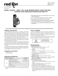
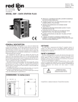
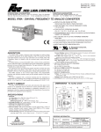
Bulletin No. PAPBH-X
Drawing No. LP0525
Effective 6/01
Tel +1 (717) 767-6511
Fax +1 (717) 764-0839
www.redlion-controls.com
MODEL PAPBH - PARADIGM PROFIBUS HOST ADAPTER
!
2 RS232 PORTS (FOR HMI AND PC)
!
PROVIDES ACCESS TO PROFIBUS NETWORK THRU DB9
CONNECTOR
!
EASILY CONFIGURED USING EDICT97
!
BASE OR DIN RAIL (OPTIONAL) MOUNTING
!
STATUS LEDs
!
FIELDBUS TYPE : PROFIBUS-DP EN 50 170, IMPLEMENTED
USING SIEMENS SPC3 ASIC
!
AUTOMATIC BAUD RATE DETECTION IN THE RANGE
9.6 KBAUD – 12 MBAUD
!
STATION ADDRESS IS SET BY PROFIBUS NETWORK DRIVER
INSTALLED ON HMI PROGRAMMING PORT
!
FREEZE MODE AND SYNCH MODE ARE SUPPORTED
!
CONFIGURATION ALLOWS FOR SINGLE IDENTIFIER AND
SPECIAL IDENTIFIER DATA AREA DESCRIPTIONS, WITHOUT
DATA CONSISTENCY SUPPORT
DESCRIPTION
SAFETY SUMMARY
The PAPBH Paradigm PROFIBUS Host Adapter provides a communication
channel from a PROFIBUS-DP EN50170 Network to a Paradigm Operator
Interface (HMI). The PROFIBUS Network is connected to the PAPBH
(Paradigm PROFIBUS Host Adapter) through a 9-pin sub-miniature D-type
female connector. The PROFIBUS Network is isolated from the control
electronics using high-speed opto-couplers and isolated from the supply with a
DC/DC converter. Three LED’s provide status information.
The PAPBH can be base mounted (using the 4 holes provided in the base
plate) or DIN rail mounted (using the optional DIN rail mounting kit).
In normal operation the PAPBH is intended to be connected via it’s HMI port
to the programming port of the HMI. Database download can still be carried out
via a connection from the PC to the PC port of the PAPBH. All connections are
made using standard Red Lion Controls programming cables. Configuration is
by the PROFIBUS Network Driver installed on the HMI programming port.
On power up the PAPBH polls the HMI for its Station Address and
configuration. During start up the PROFIBUS master attempts to parameterize
and configure the PAPBH. Following start up, data is exchanged between the
PAPBH and the HMI.
All safety related regulations, local codes and instructions that appear in the
manual or on equipment must be observed to ensure personal safety and to
prevent damage to either the instrument or equipment connected to it. If
equipment is used in a manner not specified by the manufacturer, the protection
provided by the equipment may be impaired.
CAUTION: Read complete instructions prior to
installation and operation of the unit.
ORDERING INFORMATION
MODEL NO.
PAPBH
PNO Conformance and GSD file
The PAPBH has passed the conformance test for PROFIBUS-DP Slave
Devices, Certificate No. Z00584. The PNO Identifier for this PROFIBUS
device is 0x00FC. The characteristics are described in GSD file
PCL00FC.GSD. A disk containing the GSD file and bitmap is included with
each PAPBH.
DESCRIPTION
PART NUMBER
PROFIBUS Host Adapter
PAPBH000
—
PAPBH DIN Rail Mounting Kit
(Includes 4 clips and 8 screws)
PAPBHDIN
—
Programming Cable
P890301Z
SPECIFICATIONS
1. POWER REQUIREMENTS: 11 to 30 VDC @ 3.0 W
Power Up Current: 3 A @ 2 msec
Must use a Class 2 or SELV rated power supply.
2. SERIAL PORTS:
PC Port: RS232 on an RJ-11 jack.
HMI Port: RS232 on an RJ-11 jack.
ProfiBus Port: RS485 on a DB9 connector
3. PHYSICAL DIMENSIONS: L = 5.52" (140.2 mm), W = 4.52" (114.8 mm),
H = 1.76" (44.7 mm)
4. CONSTRUCTION: Steel base plate and cover. Installation Category I,
Pollution Degree 2
5. ENVIRONMENTAL CONDITIONS:
Operating Temperature: 0 to 40 °C
Storage Temperature: -20 to 80 °C
Operating and Storage Humidity: 80% max. relative humidity (noncondensing) from 0 °C to 40 °C.
Altitude: Up to 2000 meters
DIMENSIONS In inches (mm)
1
6. CERTIFICATIONS AND COMPLIANCES:
SAFETY
IEC 1010-1, EN 61010-1: Safety requirements for electrical equipment for
measurement, control, and laboratory use, Part 1.
ELECTROMAGNETIC COMPATIBILITY
Immunity to EN 50082-2
Electrostatic discharge
Electromagnetic RF fields
Fast transients (burst)
RF conducted interference
Emissions to EN 50081-2
RF interference
WIRING AND CONNECTIONS
POWER SUPPLY REQUIREMENTS
The Operator Interface requires an 11 to 30 VDC power supply rated at
2.25 W unless otherwise stated on the label.
! The terminal may take as little as 100 mA in certain circumstances, so be
sure that the chosen power supply can operate correctly with this load.
Large switch-mode supplies tend to need a certain minimum load before
they will operate correctly.
In any case, it is very important that the power supply is mounted correctly if
the unit is to operate reliably. A very high proportion of reported problems are
caused by incorrect power supply installation, so please take care to observe the
following points...
! The power supply must be mounted close to the unit, with usually not
more than 6 feet of cable between the supply and the PAPBH. Ideally, as
short a length as is possible should be used.
EN 61000-4-2 Level 2; 4 Kv contact
Level 3; 8 Kv air
EN 61000-4-3 Level 3; 10 V/m
80 MHz - 1 GHz
EN 61000-4-4 Level 4; 2 Kv I/O
Level 3; 2 Kv power
EN 61000-4-6 Level 3; 10 V/rms 1
150 KHz - 80 MHz
!
EN 55011
Enclosure class A
Power mains class A
Note:
1. Self-recoverable loss of performance during EMI disturbance at 10 Vrms:
For operation without loss of performance:
Install 1 ferrite core RLC #FCOR0000 or equivalent, to power cable at unit.
I/O cables are routed in metal conduit connected to earth ground.
7. FIELD CONNECTIONS: Removable screw terminal blocks.
8. WEIGHT: 1.25 lb (0.58 kg)
The wire used to connect the PAPBH’s power supply should be of at least
22 gauge wire. If a longer cable run is used, you should use a heavier
gauge wire. The routing of the cable should be kept away from large
contactors, inverters and other devices which may generate significant
electrical noise.
RS232 PORT PIN OUT
Both HMI and PC ports are RS-232 ports and have the same pin-out
described below. The following illustration and table gives the pin-out of these
ports to enable such connections to be made.
STATUS LED’s
Three LED’s provide status indication and are described in Table 1. The
PROFIBUS–DP state machine is indicated by the data, WD and DP LED’s and
are described in Table 2.
Table 1
Paradigm PROFIBUS Host Adapter Status LED Description
NAME
COLOR
FUNCTION
Rear View of Unit
PROFIBUS-DP Data Exchange state
(driven by SPC3 DATA_EX pin)
DATA
Red
WD
Green
Watchdog State Machine State
DP
Red
DP Control State Machine State
The above table denotes the pin names of the RS-232 port. When connecting,
the pin name at the port is connected to the opposite of that pin name at the
destination device.
PROFIBUS CONNECTION
Table 2
Led Indication of Paradigm PROFIBUS Host Adapter State
In PROFIBUS-DP Slave State Machine
It is recommended that PROFIBUS plug connector such as Siemens part
6ES7 972 – 0BA00 – 0XA0 be used. If the PAPBH is the last unit on the
network, set the terminating resistor switch to the “ON” position.
DATA LED
(Red)
WD LED
(Green)
DP LED
(Red)
PARADIGM PROFIBUS HOST ADAPTER STATE
TROUBLESHOOTING
OFF
ON
OFF
Baud Search state
For further technical assistance, contact technical support at the appropriate
company numbers listed.
OFF
FLASHING
OFF
Baud Control State
OFF
OFF
ON
Waiting for Parameterization Telegram
OFF
OFF
FLASHING
ON
OFF
OFF
Waiting for Configuration Telegram
Data Exchange State
2
INSTALLATION ENVIRONMENT
MOUNTING
The unit should be installed in a location that does not exceed the maximum
operating temperature and provides good air circulation. Placing the unit near
devices that generate excessive heat should be avoided.
The PAPBH can be base mounted or installed using the optional DIN rail
mounting kit.
DIN RAIL MOUNTING
PANEL MOUNTING
APPLICATION
This drawing shows a typical PROFIBUS Application.
3
PROFIBUS NETWORK DRIVER APPLICATION NOTE
Introduction
The PAPBH is a gateway that allows a Paradigm Operator Interface access to a PROFIBUS-DP Network. The Host Adapter is connected to the Operator Interface
programming port allowing data transfer with Internal Communications Blocks. The PAPBH is auto-configuring for all PROFIBUS properties such as baud rate, but
needs a Station Address configured by the Operator Interface. These are set up using the PROFIBUS Network Driver described here.
Configuration
The Station Address and Input and Output Data Container Blocks are set in the Configuration Edit dialog from the Select Communications Driver dialog.
The Station Address has a default value of 126 and must be in the range 1 to 125 for normal operation.
The Input and Output Data Container Blocks are the data buffers that the PROFIBUS Network writes data to, and reads data from. These correspond to Internal
Communications Blocks and as such these must be set up in the Communications Block Table. A maximum of 116 words may be transferred per block. Data flow is
described with respect to the PROFIBUS Network - thus Input Data is written to the PROFIBUS Network and Output Data is read from the PROFIBUS Network.
Example
This example shows the PROFIBUS Node configured as Station Address 5, Communications Block A as Input Data and Communications Block B as Output Data.
Driver Configuration
Communication Block Configuration
PROFIBUS DP-SLAVE CONFIGURATION
Name
Value
Station Address
5
Input Data Container Block
A
Output Data Container Block
B
COMMUNICATION BLOCKS
DEVICE
ADDRESS
DATA TYPE
SIZE
ACCESS
UPDATE
LINKS
ENABLE
A
Internal
None
16-bit
Signed
10
Read
Auto
None
Default
B
Internal
None
16-bit
Signed
10
Read
Auto
None
Default
LIMITED WARRANTY
The Company warrants the products it manufactures against defects in materials and workmanship for a period limited to one year from the
date of shipment, provided the products have been stored, handled, installed, and used under proper conditions. The Company’s liability
under this limited warranty shall extend only to the repair or replacement of a defective product, at The Company’s option. The Company
disclaims all liability for any affirmation, promise or representation with respect to the products.
The customer agrees to hold Red Lion Controls harmless from, defend, and indemnify RLC against damages, claims, and expenses arising
out of subsequent sales of RLC products or products containing components manufactured by RLC and based upon personal injuries, deaths,
property damage, lost profits, and other matters which Buyer, its employees, or sub-contractors are or may be to any extent liable, including
without limitation penalties imposed by the Consumer Product Safety Act (P.L. 92-573) and liability imposed upon any person pursuant to
the Magnuson-Moss Warranty Act (P.L. 93-637), as now in effect or as amended hereafter.
No warranties expressed or implied are created with respect to The Company’s products except those expressly contained herein. The
Customer acknowledges the disclaimers and limitations contained herein and relies on no other warranties or affirmations.
Red Lion Controls
20 Willow Springs Circle
York PA 17402
Red Lion Controls France
56 Boulevard du Courcerin, Batiment 21,
ZI Pariest F-77183 Croissy Beaubourg
Red Lion UK Ltd
Tapton Park
Chesterfield S41 OTZ
Tel +1 (717) 767-6511
Tel +33 (64) 80 12 12
Tel +44 (1246) 22 21 22
Fax +1 (717) 764-0839
Fax +33 (64) 80 12 13
Fax +44 (1246) 22 12 22