1
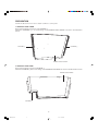
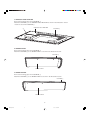
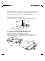
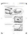
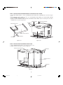
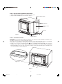
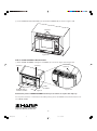
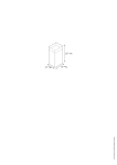
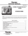
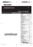
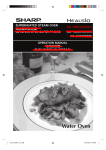
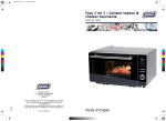
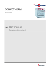
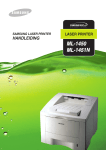
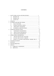
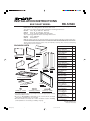
INSTALLATION INSTRUCTIONS
RK-12S30
BUILT-IN KIT MODEL
IMPORTANT: This Built-In Kit is designed for use with Sharp SuperSteam Ovens specifying a RK-12S30
Built-In Kit on the rating label on the front of the oven.
The cabinet or wall opening must be within the following dimensions:
HEIGHT 19" to 19 1/8" (482 mm - 486 mm)
WIDTH
28" to 28 1/4" (710 mm - 719 mm)
DEPTH
23 1/4" minimum (509.5 mm minimum)
The completed built-in kit frame assembly dimensions:
HEIGHT 19 1/2" (495mm)
WIDTH
30" (762mm)
NOTE: The bottom of the cut-out opening for built-in use must be 36 inches (915 mm) or higher from the floor.
PLEASE READ THESE INSTRUCTIONS THOROUGHLY BEFORE BEGINNING INSTALLATION!
The electrical requirements for this oven are 120 volts, 15 amps. The oven has a 5-15 plug
and requires a 5-15 receptacle.
PROVIDED PARTS
PART NAME
RECTIFIER
PLATE L
EXHAUST DUCT
BACK
EXHAUST
DUCT UPPER
DIVIDE PLATE L
EXHAUST EXHAUST
DUCT LEFT DUCT
RIGHT
DIVIDE PLATE R
EXHAUST DUCT BOTTOM
REAR SPACER
SCREW (A) - SHORT
FRAME
ASSEMBLY
SCREW (B) - MIDDLE
SCREW (C) - LONG
* For walls other than wood, you may need screws appropriate for that
wall to install the frame.
* Be sure to DISCONNECT THE PLUG of the oven from the electrical
outlet before installing the oven and kit.
* Because the kits are metal, due caution should be used in handling
and installation to avoid the possibility of injury.
EXHAUST DUCT BACK
PDVC-B107WRWZ
EXHAUST DUCT UPPER
PDVC-B105WRWZ
DIVIDE PLATE L
PSKR-A486WRWZ
DIVIDE PLATE R
PSKR-A487WRWZ
RECTIFIER PLATE L
PSKR-A484WRWZ
EXHAUST DUCT LEFT
PDVC-B108WRWZ
EXHAUST DUCT RIGHT
PDUC-B117WRWZ
EXHAUST DUCT BOTTOM
PDVC-B106WRWZ
FRAME ASSEMBLY
FDEC-A004WRKZ
SCREW(A)
XHTS740P08000
SCREW(B)
XMMS841P13000
SCREW(C)
XMSS827P25000
REAR SPACER
PSPAFA003WRWZ
CUSHION 1 5/8" x 16",
15 mm x 405 mm
PCUS-A245WRPZ
CUSHION 2 1/4" x 24 3/8",
5 mm x 618 mm
PCUS-A247WRPZ
CUSHION 3 1 1/8" x 27 1/8",
30 mm x 689 mm
PCUS-A249WRPZ
CUSHION 4 1/4" x 12",
5 mm x 305 mm
PCUS-A251WRPZ
CUSHION 5 1/4" x 15",
5 mm x 382 mm
PCUS-A253WRPZ
1
RK12S30 2nd
1
Q'TY
09.1.14, 11:01 AM
1
1
1
1
1
1
1
1
1
23
2
4
1
2
1
1
1
1
TINSEB184WRRZ-D92
Printed in Thailand
PREPARATION
Follow the directions from 1 to 5 to attach cushions to some parts.
1. EXHAUST DUCT UPPER
Remove the backing paper from each CUSHION 1.
Attach the CUSHIONS 1 to each side flange of the EXHAUST DUCT UPPER as shown in the illustration
below.
CUSHION 1
CUSHION 1
EXHAUST DUCT UPPER
2. EXHAUST DUCT BACK
Remove the backing paper from CUSHION 2.
Attach the CUSHION 2 at the lower flange of the EXHAUST DUCT BACK as shown in the Illustration below.
EXHAUST DUCT BACK
CUSHION 2
2
RK12S30 2nd
2
09.1.7, 5:19 PM
3. EXHAUST DUCT BOTTOM
Remove the backing paper from CUSHION 3.
Attach the CUSHION 3 to the EXHAUST DUCT BOTTOM as shown in the Illustration below.
* Start A to attach the CUSHION 3.
EXHAUST DUCT BOTTOM
A
CUSHION 3
4. DIVIDE PLATE L
Remove the backing paper from CUSHION 4.
Attach the CUSHION 4 to the DIVIDE PLATE L as shown in the Illustration below.
CUSHION 4
DIVIDE PLATE L
5. DIVIDE PLATE R
Remove the backing paper from CUSHION 5.
Attach the CUSHION 5 to the DIVIDE PLATE R as shown in the Illustration below.
CUSHION 5
DIVIDE PLATE R
3
RK12S30 2nd
3
09.1.7, 5:19 PM
STEP 1: CABINET OR WALL OPENING
Provide an opening in the wall or cabinet shown in Figure 1.
The depth should be minimum 23 1/4" (590.5 mm). The floor of the opening should be constructed of
plywood strong enough to support the weight of the oven (about 150 lbs., 68.1 kg) and should be level for
proper operation of the oven.
NOTE: While the proper functioning of the oven does not require that the opening be enclosed (with sides,
ceiling and rear partition), this may be required by local code, and it is suggested that the local code be
checked for any such requirement.
ELECTRICAL SUPPLY
At the rear of the opening, provide a 3 pronged, polarized, electrical outlet, 120 volt A.C., 15 amp. or larger.
This outlet should be located in the shaded area of Figure 1.
It is exceedingly important that the outlet be 120 volts and 15 amps. for optimum oven performance.
19" - 19 1/8"
(482 mm - 486 mm)
1 4"
23 / mm)
.5
(590
28" -
28 1/4"
(710 m
m-7
19 mm
7 7/8"
(200 mm)
Figure 1
)
CL
STEP 2: INSTALLATION OF EXHAUST DUCT BOTTOM & DIVIDE PLATE L/R
It is recommended that a sheet of cardboard or other protective material should be placed on the table or
countertop to prevent damage to the surface during assembly.
1 Place DIVIDE PLATE L/R over 2 caches on EXHAUST DUCT BOTTOM.
2 Lock them into EXHAUST DUCT BOTTOM by sliding DIVIDE PLATE L/R in the direction of the
arrow as shown in Figure 2-A.
3 Tighten 4 SCREWS (A) from the bottom at the left and right sides as shown in Figures 2 and 2-A.
DIVIDE PLATE L
DIVIDE PLATE R
Figure 2-A
SCREW (A)
EXHAUST
DUCT BOTTOM
Figure 2
SCREW (A)
Catches
SCREW (A)
4
RK12S30 2nd
4
09.1.14, 11:01 AM
STEP 3: EXHAUST DUCT BOTTOM INSTALLATION
1 Place the oven onto the EXHAUST DUCT BOTTOM, lowering the 4 feet of the oven onto the projections
at the 4 corners of EXHAUST DUCT BOTTOM as shown in Figure 3-A.
Projection
EXHAUST DUCT
BOTTOM
Figure 3-A
Figure 3
STEP 4: EXHAUST DUCT BACK INSTALLATION
1 Remove 2 screws (#1) from upper both
sides of the oven as shown in Figure 4-A
to install the EXHAUST DUCT BACK.
(Save 2 screws to be used at step 4-2.)
#1
Figure 4-A
EXHAUST DUCT BACK
2 Secure EXHAUST DUCT BACK to the oven
with the screws (#1) removed at step 4-1 and
a SCREW (A) as shown in Figure 4-B.
#1
SCREW (A)
Figure 4-B
5
RK12S30 2nd
5
09.1.7, 5:19 PM
STEP 5: INSTALLATION OF REAR SPACER and EXHAUST DUCT UPPER
1 Attach RECTIFIER PLATE L to inside of EXHAUST DUCT UPPER with 4 SCREWS (A) as shown in Figure
5-A.
2 Place EXHAUST DUCT UPPER over the oven and EXHAUST DUCT BACK, and attach REAR SPACER
with 2 SCREWS (A) in Figure 5-B.
3 Tighten together EXHAUST DUCT UPPER and EXHAUST DUCT BACK at the left and right sides with 2
SCREWS (A) as shown in Figure 5-B.
REAR SPACER
EXHAUST DUCT UPPER
SCREW (A)
RECTIFIER PLATE L
SCREW (A)
EXHAUST DUCT UPPER
SCREW (A)
SCREW (A)
EXHAUST DUCT BACK
Figure 5-A
Figure 5-B
STEP 6: INSTALLATION OF EXHAUST DUCT LEFT
1 Attach EXHAUST DUCT LEFT to the left wall of the oven.
2 Tighen with 6 screws (A) as shown in Figure 6.
EXHAUST DUCT UPPER
SCREW (A)
EXHAUST DUCT
LEFT
SCREW (A)
DIVIDE PLATE L
Figure 6
6
RK12S30 2nd
6
09.1.8, 4:21 PM
STEP 7: INSTALLATION OF EXHAUST DUCT RIGHT
1 Attach EXHAUST DUCT RIGHT to the right wall of the oven.
2 Tighten with 4 SCREWS (A) as shown in the Figure 7.
EXHAUST DUCT UPPER
SCREW (A)
EXHAUST DUCT
RIGHT
SCREW (A)
Figure 7
DIVIDE PLATE R
STEP 8: OVEN INSTALLATION
CAUTION: Never hold the handle when moving the oven. Two persons are required to install the oven.
1 Establish center line of opening and mark front edge.
2 Place the oven on a table or stand positioned in front of the cabinet where the oven is to be installed.
One person should hold the oven while the other connects it to the electrical outlet.
3 Install the oven into the shelf with adjusting
mark on EXHAUST DUCT BOTTOM to the center line
marked on front edge as shown in Figures 8 and 8-A. Then push the oven until the flange of EXHAUST
DUCT BOTTOM touches the edge of the wall or cabinet opening. Avoid pinching the cord between the
oven and any wall as shown in Figure 8.
Figure 8-A
28" - 28 1
/4" (710
Flange
Figure 8
CL
7
RK12S30 2nd
7
09.1.7, 5:19 PM
mm - 7
19 mm
)
4 Secure EXHAUST DUCT BOTTOM to the shelf with 2 SCREWS (B) as shown in Figures 8-B.
SCREW (B)
Figure 8-B
STEP 9: FRAME ASSEMBLY INSTALLATION
1 Attach FRAME ASSEMBLY and tighten 4 SCREWS (C) as shown in Figure 9 and Figure 9-A.
SCREW (C)
SCREW (C)
FRAME
ASSEMBLY
SCREW (C)
BOTTOM PANEL of
FRAME ASSEMBLY
SCREW (C)
Figure 9-A
Figure 9
Pull bottom panel of FRAME ASSEMBLY toward you to remove or replace the drip tray.
For any other assistance or information about this product, please call SHARP's Customer Assistance Center 1-800-BE-SHARP.
®
SHARP ELECTRONICS CORPORATION
Sharp Plaza, Mahwah, NJ 07495-1163
8
RK12S30 2nd
8
09.1.7, 5:19 PM