1
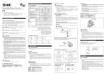
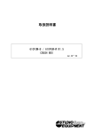
Book_516591_0507_SP6.book Seite 1 Dienstag, 5. Juni 2007 8:53 08
Bedienungsanleitung
Instructions for use
Notice d’emploi
Istruzioni per l’uso
Instrucciones de uso
Gebruiksaanwijzing
A 3700
Book_516591_0507_SP6.book Seite 2 Dienstag, 5. Juni 2007 8:53 08
Book_516591_0507_SP6.book Seite 1 Dienstag, 5. Juni 2007 8:53 08
Deutsch
English
Français
Italiano
Español
Nederlands
Book_516591_0507_SP6.book Seite 2 Dienstag, 5. Juni 2007 8:53 08
Book_516591_0507_SP6.book Seite 1 Dienstag, 5. Juni 2007 8:53 08
A 3700
Die Breitbandantenne mit integriertem Antennenverstärker
dient der Verbesserung der Übertragungsicherheit bei Vielkanalanlagen. Sie kann an die Empfänger EM 3731, EM 3732 und
EM 3732 Command angeschlossen werden.
Merkmale
y Richtcharakteristik omnidirektional
y Vierstufig einstellbare Verstärkung bis 15 dB zum Ausgleich
der Kabeldämpfung
y Spannungsversorgung über den HF-Ausgang des Antennenverstärkers
y Bypass bei Spannungsausfall
y Gut sichtbare LED-Anzeige der Betriebszustände
y Antennenverstärker im robusten, spritzwassergeschützten
Ganzmetallgehäuse
y Einfache Montage am Stativ durch integrierte 3/8“ oder
5/8“ Gewinde
Lieferumfang
y Breitbandantenne A 3700 mit integriertem Antennenverstärker
y Bedienungsanleitung
y Einstellwerkzeug
1
Book_516591_0507_SP6.book Seite 2 Dienstag, 5. Juni 2007 8:53 08
Übersicht über die Bedienelemente
쐃
쐇
쐃
쐋
쐃 LED Betriebsanzeige
쐇 BNC-Buchse, HF-Ausgang (RF out)
쐋 Schalter zur Verstärkungseinstellung
쐏 Stativgewinde (3/8‘‘ oder 5/8‘‘)
LED Betriebsanzeige
Farbe der LED
rot
2
Schalterstellung
Verstärkung
bypass/-3 dB
grün
+5 dB
blau
+10 dB
weiß
+15 dB
쐏
Book_516591_0507_SP6.book Seite 3 Dienstag, 5. Juni 2007 8:53 08
Hinweise
y Halten Sie die Kabelstrecke zwischen Antenne und Empfänger so kurz wie möglich.
y Halten Sie zwischen Antenne und Sender einen Mindestabstand von 5 m ein.
y Lassen Sie zwischen Antenne und Metallobjekten (auch
Stahlbetonwände) einen Mindestabstand von 50 cm.
y Halten sie zwischen den Antennen einen Mindestabstand
von 1 m ein.
y Richten Sie die Antennen für den optimalen Empfang
immer vertikal aus.
Geeignete Kabeltypen und dazu passende
Verstärkungseinstellungen
Je nach Kabellänge müssen Sie die Verstärkungseinstellung mit
dem Schalter � anpassen (siehe Abbildung Seite 2).
Verstärkungseinstellung für Kabeltyp RG 58 / GZL 1019
b 5 dB
10 dB 15 dB
Verstärkungseinstellung für Kabeltyp RG 213 / GZL5000
b
5 dB
10 dB
15 dB
Verstärkungseinstellung für besonders dämpfungsarme 1/2 " Kabel
b
0
0
5 dB
10
30
20
60
10 dB
15 dB
30
40
50
60
70
80
90
100
90 120 150 180 210 240 270 300 130
110 m
360 ft
Kabellänge (m/ft)
3
Book_516591_0507_SP6.book Seite 4 Dienstag, 5. Juni 2007 8:53 08
Zubehör
Kabel 1 m
GZL 1019-A1
Art. Nr.: 2324
Kabel 5 m
GZL 1019-A5
Art. Nr.: 2325
Kabel 10 m
GZL 1019-A10
Art. Nr.: 2326
Gelenkfuß
GZG 1029
Art. Nr.: 3226
Wandbefestigungsplatte
für GZG 1029
GZP 10
Art. Nr.: 3193
Technische Daten
Antenne A 3700
4
Frequenzbereich:
Richtwirkung:
470–866 MHz
omnidirektional
Verstärkung (Booster) typ:
bypass (-3 dB), 5 dB, 10 dB,
15 dB einstellbar,
ohne Fernspeisung: -6 dB
Impedanz:
50 Ohm
OIP3:
>= 32 dBm
Anschlüsse:
1 x BNC Buchse
Stromversorgung:
9–15 V DC / 160–100 mA,
Fernspeisung über
Antennenkabel (RF-out Buchse)
Stativgewinde:
3/8‘‘ oder 5/8‘‘
Abmessungen:
250 x 165 x 23 mm
Gewicht mit Verstärker:
ca. 390 g
Book_516591_0507_SP6.book Seite 5 Dienstag, 5. Juni 2007 8:53 08
Herstellererklärungen
Garantie
2 Jahre
EG-Konformitätserklärung
Diese Geräte entsprechen den grundlegenden Anforderungen
und den weiteren Vorgaben der Richtlinie 99/5/EC.
Die Erklärung steht im Internet unter www.sennheiser.com zur
Verfügung.
Vor Inbetriebnahme sind die jeweiligen länderspezifischen Vorschriften zu beachten!
5
Book_516591_0507_SP6.book Seite 6 Dienstag, 5. Juni 2007 8:53 08
6
Book_516591_0507_SP6.book Seite 1 Dienstag, 5. Juni 2007 8:53 08
A 3700
The A 3700 is a broadband omni-directional antenna with
integrated antenna booster for improving the transmission
reliability in multi-channel systems. The A 3700 can be
connected to EM 3731, EM 3732 and EM 3732 Command
receivers.
Features
y Omni-directional antenna
y Amplification adjustable in 4 steps (up to 15 dB) to
compensate for cable losses
y DC powered from the receiver via the antenna cable
y By-pass switch in case of power failure (ie: antenna then
becomes a passive antenna)
y LED operation indicator
y Antenna booster housed in a rugged, splash-proof all-metal
housing
y Standard 3/8“ or 5/8“ mounting thread
Delivery includes
y A 3700 broadband omni-directional antenna with integrated
antenna booster
y Instructions for use
y Adjustment tool
1
Book_516591_0507_SP6.book Seite 2 Dienstag, 5. Juni 2007 8:53 08
Operating elements
쐃
쐇
쐃
쐋
쐃 LED operation indicator
쐇 BNC socket, RF output (RF out)
쐋 Amplification selector
쐏 Mounting thread (3/8‘‘ or 5/8‘‘)
LED operation indication
LED color
red
green
2
Selector position Amplification
bypass/-3 dB
+5 dB
blue
+10 dB
white
+15 dB
쐏
Book_516591_0507_SP6.book Seite 3 Dienstag, 5. Juni 2007 8:53 08
Notes
y Keep the cable run between antenna and receiver as short
as possible.
y Observe a minimum distance of 5 m between antenna and
transmitter.
y Observe a minimum distance of 50 cm between antenna
and metal objects (such as cross members or reinforcedconcrete walls).
y Observe a minimum distance of 1 m between antennas.
y For optimum reception, always align the antennas
vertically.
Suitable cable types and
corresponding amplification settings
Depending on the cable length, you have to adjust the
amplification using the selector � (see diagram on page 2).
Amplification setting for RG 58 cable / GZL 1019
b 5 dB
10 dB 15 dB
Amplification setting for RG 213 cable / GZL5000
b
5 dB
10 dB
15 dB
Amplification setting for very low-attenuation 1/2 " cable
b
0
0
5 dB
10
30
20
60
10 dB
15 dB
30
40
50
60
70
80
90 100
90 120 150 180 210 240 270 300 130
110 m
360 ft
Cable length (m/ft)
3
Book_516591_0507_SP6.book Seite 4 Dienstag, 5. Juni 2007 8:53 08
Accessories
BNC/BNC cable, 1 m
GZL 1019-A1
Cat. No.: 2324
BNC/BNC cable, 5 m
GZL 1019-A5
Cat. No.: 2325
BNC/BNC cable, 10 m
GZL 1019-A10
Cat. No.: 2326
Swivel joint
GZG 1029
Cat. No.: 3226
Mounting plate
for GZG 1029
GZP 10
Cat. No.: 3193
Specifications
A 3700 antenna
Frequency range:
470–866 MHz
Radiation pattern:
omni-directional
Amplification (booster) typ.: bypass (-3 dB), 5 dB, 10 dB,
15 dB adjustable, without
DC feed: -6 dB
Impedance:
50 ohms
OIP3:
>= 32 dBm
RF connection:
1 x BNC socket
Power supply:
9–15 V DC / 160–100 mA,
DC feed via antenna cable
(RF OUT socket)
Mounting connection:
3/8‘‘ or 5/8‘‘ thread
4
Dimensions:
250 x 165 x 23 mm
Weight incl. booster:
approx. 390 g
Book_516591_0507_SP6.book Seite 5 Dienstag, 5. Juni 2007 8:53 08
Manufacturer Declarations
Warranty
2 years
CE Declaration of Conformity
This equipment is in compliance with the essential requirements and other relevant provisions of Directive 99/5/EC. The
declaration is available on the Internet at www.sennheiser.com.
Before putting the device into operation, please observe the
respective country-specific regulations!
5
Book_516591_0507_SP6.book Seite 6 Dienstag, 5. Juni 2007 8:53 08
6
Book_516591_0507_SP6.book Seite 1 Dienstag, 5. Juni 2007 8:53 08
A 3700
L’A 3700 est une antenne omni-directionnelle à large bande
avec booster d’antenne intégré, prévu pour améliorer la fiabilité
de transmission dans les installations multi-canaux. L’A 3700
peut être raccordée aux récepteurs EM 3731, EM 3732 et
EM 3732 Command.
Points forts
y Antenne omni-directionnelle
y Amplification réglable selon 4 positions (jusqu’à 15 dB) pour
compenser les pertes dans les câbles
y Alimentation CC par le récepteur via le câble d’antenne
y Sélecteur Bypass en cas de rupture d'alimentation (dans ce
cas, l’antenne devient passive)
y Indicateur LED de fonctionnement
y Booster d’antenne dans un boîtier métallique robuste,
résistant aux éclaboussures
y Trou fileté pour fixation (3/8“ ou 5/8“)
Contenu
y Antenne omni-directionnelle à large bande avec booster
d’antenne intégré A 3700
y Notice d’emploi
y Outil de réglage
1
Book_516591_0507_SP6.book Seite 2 Dienstag, 5. Juni 2007 8:53 08
Commandes
쐃
쐇
쐃
쐋
쐃 Indicateur LED de fonctionnement
쐇 Prise BNC, sortie HF (RF out)
쐋 Sélecteur d’amplification
쐏 Trou fileté (3/8‘‘ ou 5/8‘‘)
Affichage LED de fonctionnement
Couleur
de la LED
rouge
2
Position du
sélecteur
Amplification
bypass/-3 dB
vert
+5 dB
bleu
+10 dB
blanc
+15 dB
쐏
Book_516591_0507_SP6.book Seite 3 Dienstag, 5. Juni 2007 8:53 08
Remarques
yMaintenez le câble reliant l’antenne au récepteur aussi court
que possible.
yRespectez une distance minimale de 5 m entre l’antenne et
l’émetteur.
yRespectez une distance minimale de 50 cm entre l’antenne
et les objets métalliques (tels que les structures
d’éclairage ou les murs en béton armé).
yRespectez une distance minimale de 1 m entre les antennes.
yPour une réception optimale, alignez toujours les antennes
verticalement.
Types de câble appropriés
et réglages d’amplification correspondants
Réglez l’amplification en fonction de la longueur du câble, via le
sélecteur � (voir l’illustration à la page 2).
Réglage d'amplification pour câble RG 58 / GZL 1019
b 5 dB
10 dB 15 dB
Réglage d'amplification pour câble RG 213 / GZL5000
b
5 dB
10 dB
15 dB
Réglage d'amplification pour câble 1/2 ", à très faible atténuation
b
0
0
5 dB
10
30
20
60
10 dB
15 dB
30
40
50
60
70
80
90 100
90 120 150 180 210 240 270 300 130
110 m
360 ft
Longueur du câble (m/ft)
3
Book_516591_0507_SP6.book Seite 4 Dienstag, 5. Juni 2007 8:53 08
Accessoires
Câble BNC/BNC, 1 m
GZL 1019-A1
N° Réf. : 2324
Câble BNC/BNC, 5 m
GZL 1019-A5
N° Réf. : 2325
Câble BNC/BNC, 10 m
GZL 1019-A10
N° Réf. : 2326
Articulation à rotule
GZG 1029
N° Réf. : 3226
Plaque de montage
pour GZG 1029
GZP 10
N° Réf. : 3193
Caractéristiques techniques
Antenne A 3700
Plage de fréquences :
470–866 MHz
Directivité :
omni-directionnelle
Amplification (booster) typ. : bypass (-3 dB), 5 dB, 10 dB,
15 dB réglable, sans
alimentation externe CC : -6 dB
Impédance :
50 ohms
OIP3 :
>= 32 dBm
Raccordement HF :
1 x prise BNC
Alimentation :
9–15 V DC / 160–100 mA,
alimentation externe CC via le
câble d’antenne (prise RF OUT)
Montage :
trou fileté (3/8‘‘ ou 5/8‘‘)
4
Dimensions :
250 x 165 x 23 mm
Poids avec booster :
env. 390 g
Book_516591_0507_SP6.book Seite 5 Dienstag, 5. Juni 2007 8:53 08
Déclarations du fabricant
Garantie
2 ans
Déclaration de conformité pour
la CEE
Cet appareil est conforme aux exigences essentielles et aux
autres dispositions pertinentes de la Directive 99/5/EC.
Vous trouvez cette
www.sennheiser.com.
déclaration
dans
l’Internet
sous
Avant d’utiliser cet appareil, veuillez observer les dispositions
légales en vigueur dans votre pays !
5
Book_516591_0507_SP6.book Seite 6 Dienstag, 5. Juni 2007 8:53 08
6
Book_516591_0507_SP6.book Seite 1 Dienstag, 5. Juni 2007 8:53 08
A 3700
L'antenna direzionale per banda larga con booster d'antenna
integrato serve per una migliore sicurezza di trasmissione negli
impianti multicanale. Può essere collegata ai ricevitori EM 3731,
EM 3732 e EM 3732 Command.
Caratteristiche
y Caratteristica di direttività omnidirezionale
y Guadagno regolabile su quattro posizioni fino a 15 dB per
compensare l'attenuazione del cavo
y Alimentazione tramite uscita HF del booster d'antenna
y Bypass in caso di avaria elettrica
y Display LED ben visibile per indicare lo stato di funzionamento
y Booster d'antenna in alloggiamento robusto, impermeabile e
interamentemetallico
y Facile montaggio sul supporto grazie alla filettatura da 3/8“
o 5/8“
Dotazione di consegna
y Antenna per banda larga A 3700 con booster d'antenna integrato
y Istruzioni per l'uso
y Strumento di regolazione
1
Book_516591_0507_SP6.book Seite 2 Dienstag, 5. Juni 2007 8:53 08
Panoramica degli elementi di
comando
쐃
쐇
쐃
쐋
쐏
쐃 LED indicatore dello stato di funzionamento
쐇 Presa BNC, uscita HF (RF out)
쐋 Interruttore per impostare l'amplificazione
쐏 Filettatura supporto (3/8‘‘ o 5/8‘‘)
LED indicatore dello stato di funzionamento
Colore del LED
Rosso
Verde
2
Posizione
interruttore
Guadagno
Bypass/-3 dB
+5 dB
Blu
+10 dB
Bianco
+15 dB
Book_516591_0507_SP6.book Seite 3 Dienstag, 5. Juni 2007 8:53 08
Nota
y Il cavo tra l'antenna e il ricevitore deve essere il più cortopossibile.
y Mantenete una distanza minima di 5 m tra l'antenna e il
trasmettitore.
y Mantenere una distanza minima di 50 cm tra l'antenna e
gli oggetti metallici (anche dalle pareti in cemento
armato).
y Mantenete una distanza minima di 1 m tra le antenne !
y Orientare sempre l'antenna in verticale per la migliore ricezione.
Tipi di cavi adatti e relative impostazioni
corrette dell'amplificazione
A seconda della lunghezza del cavo, adattare l'impostazione
dell'amplificazione mediante l'interruttore � (vedere figura a
pagina 2).
Impostazione guadagno per tipo di cavo RG 58 / GZL 1019
b 5 dB
10 dB 15 dB
Impostazione guadagno per tipo di cavo RG 213 / GZL5000
b
5 dB
10 dB
15 dB
Impostazioni guadagno per cavi 1/2 " con attenuazione
particolarmente ridotta
b
0
0
5 dB
10
30
20
60
10 dB
15 dB
30
40
50
60
70
80
90
100
90 120 150 180 210 240 270 300 130
110 m
360 ft
Lunghezza cavo (m/ft)
3
Book_516591_0507_SP6.book Seite 4 Dienstag, 5. Juni 2007 8:53 08
Accessori
Cavo1 m
GZL 1019-A1
Art. N.:
2324
Cavo 5 m
GZL 1019-A5
Art. N.:
2325
Cavo 10 m
GZL 1019-A10
Art. N.:
2326
Base articolata
GZG 1029
Art. N.:
3226
Piastra di fissaggio a
parete per GZG 1029
GZP 10
Art. N.:
3193
Dati tecnici
Antenna A 3700
Campo di frequenza:
Direttività:
470–866 MHz
omnidirezionale
Amplificatore (Booster) tipo: bypass (-3 dB), 5 dB, 10 dB,
15 dB regolabile, senza
alimentazione remota: -6 dB
4
Impedenza:
50 Ohm
OIP3:
>= 32 dBm
Collegamenti:
1 x presa BNC
Alimentazione elettrica:
9–15 V DC / 160–100 mA,
alimentazione remota tramite
cavo dell'antenna (presa RF out)
Filettatura supporto:
3/8‘‘ o 5/8‘‘
Dimensioni:
250 x 165 x 23 mm
Peso con booster:
ca. 390 g
Book_516591_0507_SP6.book Seite 5 Dienstag, 5. Juni 2007 8:53 08
Dichiarazioni del produttore
Garanzia
2 anni
Dichiarazione di conformità
CE
Questi apparecchi sono conformi ai requisiti fondamentali e alle
ulteriori disposizioni della direttiva 99/5/CE.
La dichiarazione è disponibile all'indirizzo www.sennheiser.com.
Prima della messa in funzione osservare le normative specifiche
del paese di utilizzo!
5
Book_516591_0507_SP6.book Seite 6 Dienstag, 5. Juni 2007 8:53 08
6
Book_516591_0507_SP6.book Seite 1 Dienstag, 5. Juni 2007 8:53 08
A 3700
La antena de banda ancha con amplificador de antena integrado sirve para mejorar la seguridad de transmisión en los
equipos multicanal. Se puede conectar a los receptores
EM 3731, EM 3732 y EM 3732 Command.
Características
y Característica direccional omnidireccional
y Amplificación regulable en cuatro niveles hasta 15 dB para
compensar la atenuación del cable
y Alimentación eléctrica a través de la salida AF del amplificador de antena
y Bypass en caso de caída de tensión
y Indicador LED con buena visibilidad de los estados de funcionamiento
y Amplificador de antena en una carcasa totalmente de metal
resistente y protegida contra las salpicaduras de agua
y Fácil montaje en el soporte mediante la rosca de 3/8" o de
5/8" integrada
Volumen de suministro
y Antena de banda ancha A 3700 con amplificador de antena
integrado
y Instrucciones de uso
y Herramienta de ajuste
1
Book_516591_0507_SP6.book Seite 2 Dienstag, 5. Juni 2007 8:53 08
Vista general de los elementos de
control
쐃
쐇
쐃
쐋
쐃 Indicador LED de funcionamiento
쐇 Hembrilla BNC, salida AF (RF out)
쐋 Interruptor para ajustar la amplificación
쐏 Rosca del soporte (de 3/8" o de 5/8"‘)
Indicador LED de funcionamiento
Color del LED
rojo
verde
2
Posición del
interruptor
Amplificación
bypass/-3 dB
+5 dB
azul
+10 dB
blanco
+15 dB
쐏
Book_516591_0507_SP6.book Seite 3 Dienstag, 5. Juni 2007 8:53 08
Notas
y Mantenga lo más corto posible el recorrido del cable entre
la antena y el receptor.
y Mantenga una distancia mínima de 5 m entre la antena y
el emisor.
y Deje una distancia mínima de 50 cm entre la antena y los
objetos metálicos (incluidas las paredes de hormigón
armado).
y Mantenga una distancia mínima de 1 m entre las antenas.
y Para conseguir una recepción óptima, oriente las antenas
siempre verticalmente.
Tipos de cable adecuados y ajuste de la
amplificación correspondiente a cada tipo
Dependiendo de la longitud del cable, debe adaptar el ajuste de
amplificación con el interruptor � (ver la ilustración de la
página 2).
Ajuste de amplificación para el tipo de cable RG 58 / GZL 1019
b 5 dB
10 dB 15 dB
Ajuste de amplificación para el tipo de cable RG 213 / GZL5000
b
5 dB
10 dB
15 dB
Ajuste de amplificación para cables de atenuación reducida 1/2 "
b
0
0
5 dB
10
30
20
60
10 dB
15 dB
30
40
50
60
70
80
90
100
90 120 150 180 210 240 270 300 130
110 m
360 ft
Longitud del cable (m/ft)
3
Book_516591_0507_SP6.book Seite 4 Dienstag, 5. Juni 2007 8:53 08
Accesorios
Cable de 1 m
GZL 1019-A1
nº art. : 2324
Cable de 5 m
GZL 1019-A5
nº art .: 2325
Cable de 10 m
GZL 1019-A10
nº art .: 2326
Pie articulado
GZG 1029
nº art .: 3226
Placa de sujeción a la
pared para GZG 1029
GZP 10
nº art :
3193
Especificaciones técnicas
Antena A 3700
Gama de frecuencias:
Efecto direccional:
470–866 MHz
omnidireccional
Amplificación (Booster) tipo: bypass (-3 dB), 5 dB, 10 dB,
15 dB regulable,
sin alimentación a distancia: -6
dB
4
Impedancia:
50 ohmios
OIP3:
>= 32 dBm
Conexiones:
1 x hembrilla BNC
Alimentación de corriente:
9–15 V CC / 160–100 mA,
Alimentación a distancia a través
del cable de antena (hembrilla
RF-out)
Rosca del soporte:
de 3/8" o de 5/8"
Dimensiones:
250 x 165 x 23 mm
Peso con amplificador:
aprox. 390 g
Book_516591_0507_SP6.book Seite 5 Dienstag, 5. Juni 2007 8:53 08
Declaraciones del fabricante
Garantía
2 años
Declaración de conformidad
de la CE
Estos aparatos cumplen las exigencias básicas y otros requisitos
de la Directiva 99/5/CE.
La declaración está disponible en la dirección de Internet
www.sennheiser.com.
Antes de la puesta en funcionamiento se deben observar las
normas específicas de cada país.
5
Book_516591_0507_SP6.book Seite 6 Dienstag, 5. Juni 2007 8:53 08
6
Book_516591_0507_SP6.book Seite 1 Dienstag, 5. Juni 2007 8:53 08
A 3700
De breedbandantenne met geïntegreerde antenneversterker
dient voor een nog betrouwbaarder overdracht bij
meerkanaalsinstallaties. De antenne kan op de ontvangers
EM 3731, EM 3732 en EM 3732 Command worden aangesloten.
Kenmerken
y Richtkarakteristiek vanaf alle kanten
y In vier standen instelbare versterking tot 15 dB ter
compensatie van de kabeldemping
y Voedingsspanning
antenneversterker
via
de
HF-uitgang
van
de
y Bypass bij spanningsuitval
y Goed zichtbare LED-aanduiding voor de bedrijfstoestanden
y Antenneversterker in een robuuste, spatwaterdichte geheel
metalen behuizing
y Eenvoudige montage op statief door geïntegreerde 3/8“- of
5/8“-schroefdraad
Omvang levering
y Breedbandantenne
antenneversterker
A 3700
met
geïntegreerde
y Gebruiksaanwijzing
y Instelgereedschap
1
Book_516591_0507_SP6.book Seite 2 Dienstag, 5. Juni 2007 8:53 08
Overzicht van de
bedieningselementen
쐃
쐇
쐃
쐋
쐃 LED-bedrijfsaanduiding
쐇 BNC-bus, HF-uitgang (RF out)
쐋 Schakelaar voor het instellen van de versterking
쐏 Statiefschroefdraad (3/8‘‘ of 5/8‘‘)
LED-bedrijfsaanduiding
Kleur van
de LED
rood
2
Schakelaarstand
Versterking
bypass/-3 dB
groen
+5 dB
blauw
+10 dB
wit
+15 dB
쐏
Book_516591_0507_SP6.book Seite 3 Dienstag, 5. Juni 2007 8:53 08
Opmerking
y Houd de kabel tussen de antenne en de ontvanger zo kort
mogelijk.
y Houd tussen antenne en zender een minimale afstand van
5 meter aan.
y Laat tussen de antenne en metalen voorwerpen (ook
wanden van gewapend beton) een minimale
tussenruimte van 50 cm.
y Houd tussen de antennes een minimale afstand van 1
meter aan.
y Richt de antennes voor een optimale ontvangst altijd
verticaal uit.
Geschikte kabeltypen en bijpassende
versterkerinstellingen
Afhankelijk van de lengte van de kabel moet u de
versterkerinstelling met behulp van de schakelaar �
aanpassen (zie afbeelding pagina 2).
Versterkerinstelling voor kabeltype RG 58 / GZL 1019
b 5 dB
10 dB 15 dB
Versterkerinstelling voor kabeltype RG 213 / GZL5000
b
5 dB
10 dB
15 dB
Versterkerinstelling voor bijzonder dempingsarme 1/2"-kabel
b
0
0
5 dB
10
30
20
60
10 dB
15 dB
30
40
50
60
70
80
90
100
90 120 150 180 210 240 270 300 130
110 m
360 ft
Kabellengte (m/ft)
3
Book_516591_0507_SP6.book Seite 4 Dienstag, 5. Juni 2007 8:53 08
Toebehoren
Kabel 1 m
GZL 1019-A1
Art. nr.: 2324
Kabel 5 m
GZL 1019-A5
Art. nr.: 2325
Kabel 10 m
GZL 1019-A1
Art. nr.: 2326
Scharnierpoot
GZG 1029
Art. nr.: 3226
Wandplaat
voor GZG 1029
GZP 10
Art. nr.: 3193
Technische gegevens
Antenne A 3700
4
Frequentiebereik:
Richtwerking:
470 – 866 MHz
vanaf alle kanten
Versterking (booster) type:
bypass (-3 dB), 5 dB, 10 dB,
15 dB instelbaar,
zonder voeding op afstand -6 dB
Impedantie:
50 ohm
OIP3:
>= 32 dBm
Aansluitingen:
1 x BNC-bus
Voedingsspanning:
9 – 15 V DC / 160 – 100 mA,
Voeding op afstand via
antennekabel (RF-out bus)
Statiefschroefdraad:
3/8‘‘ of 5/8‘‘
Afmetingen:
250 x 165 x 23 mm
Gewicht met versterker:
ca. 390 g
Book_516591_0507_SP6.book Seite 5 Dienstag, 5. Juni 2007 8:53 08
Verklaringen van de fabrikant
Garantie
2 jaar
EG – Verklaring van
overeenstemming
Deze apparaten voldoen aan de fundamentele eisen en overige
gegevens van de richtlijn 99/5/EG.
De verklaring is op internet onder www.sennheiser.com
beschikbaar.
Lees voor de inbedrijfstelling eerst de specifieke voorschriften
door, die voor uw land van toepassing zijn!
5
Book_516591_0507_SP6.book Seite 1 Dienstag, 5. Juni 2007 8:53 08
Sennheiser electronic GmbH & Co. KG
30900 Wedemark, Germany
Phone +49 (5130) 600 0
Fax +49 (5130) 600 300
www.sennheiser.com
Printed in Germany
Publ. 05/07
516591/A01