1
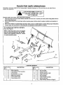
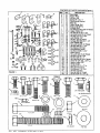
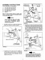
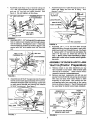
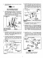
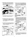
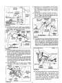
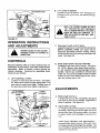
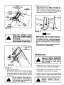
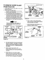
!
i
owners
manual
Model
No.
486.244120
48"
DOZER BLADE
48" DOZER BLADE
CAUTION:
Read Rules for
Safe Operation
and Instructions
Carefully
•
•
•
•
Assembly
Operation
Customer Responsibilities
Repair Parts
Sears,
Roebuck
and Co., Hoffman
Estates,
IL. 60179
U.S.A.
PRINTED IN U.S.A.
RULES FOR SAFE OPERATIONS
Remember, any power equipment can cause injury if operated improperly or if the user does not und_ "stand how ta
operate the equipment.
I
.IL.
I
IMPORTANT
_1_
SAFETY PRECAUTIONS.
IT MEANS
-- ATTENTION. BECOME ALERT, YOUR
LOOK FOR THIS SYMBOL TO POINT OUT
SAFETY IS INVOLVED.
I
I
Exercise caution at all times, when using power equipment.
1. Read the tractor and dozer blade owners manuals and know how to operate your tractor, before using tractor with the
dozer blade attachment.
2.
Never operate tractor and dozer blade without wearing proper clothing suited to weather conditionsand operation of
controls.
3.
4.
Never allow children to operate tractor and dozer blade, and do not allow adults to operate without proper instructions.
Always begin with transmission in first (low) gear and gradually increase speed as required.
48" DOZER BLADE CARTON CONTENTS
(Also See Page 3)
While confirming parts count, we suggest
that you clear any paint from the 1/8" pin
holes in part reference numbers 2, 3 and 4
to make assembly easier,
13
CARTON CONTENTS
REF
NO.
QTY.
1
2
3
4
5
6
7
(1)
(1)
(1)
DESCRIPTION
Blade Assembly
Channel/Pivot Plate Assembly
Lift Assembly
Guide Bracket Assembly
Blade Pivot Bracket
Frame Bracket (RH)
Frame Bracket (LH)
2
REF.
NO.
QTY.
8
9
10
11
12
13
14
(2)
(1)
(1)
(2)
(1)
(1)
(2)
(1)
DESCRIPTION
Lift Pivot Plate
Support Bracket
Handle Assembly w/grip
Angle Lock Bars
Grip Assembly
Control Cable Assembly
Spring Assembly
Parts Package (Shown on Page 3)
CONTENTS OF PARTS PACKAGE (Figure 1)
A
B
C
D
E
F
1
(
_
d
_
H
I
G
J
K
I
Stop Angle
Keeper Plate
Lift Arm Link
Spdng Pin 1/4 x 1"
Cable Mount Bracket
Nylon tie
,
,_i!
Angle Lock Spring
Bolt End
/ Shoulder
Cable Fitting,
Hex Whizlock Nut 3/8-16 Thread
(I0)
Hairpin Cotter 1/8"
M
L
N
0
P
Hex Lock Nut 5/16-18 Thread
111)1 HexBolt5116-18x1-112"
Hex Bolt 112-13 x 2-3/4"
2)
2)
Lock Washer 1/2"
Hex Nut 1/2-13 Thread
Q
R
2/
Carriage
Bolt 3/8-16
x 1-1/4"
Lock Washer
3/8"
T
U
Hex Bolt 3/8-16 x 1-1/4"
Rat Washer 3/8" Std.
W
V
X
Y
Z
A.A
AB
AC
A[_
i_)I
11
AF
AE
AE
AFt
FIGURE 1
Hex Bolt 1/4-20 x 1-1/4 °
Pivot Bushing (short)
Spacer (long)
I-rex Lock Nut 1/4-20 Thread
Hex Bolt 1/4-20 x 5/8"
Hex Bolt 3/8-16 x 1"
Hex Jam Nut 5/16-24 Thread
Clevis Pin 3/8" Dia. x 3/4" Lg.
Hairpin Cotter 5/32"
i! I
2)
AJ ,
AI
AK
!}
Hex Bolt 1/2-13 x 4" Lg.
Handle
Hex JamGuide
Nut 1/2-13
Rat Washer 7116" Std.
Hex Nut 3/8-16 Thread
Lift Rod Trunnion
Hex Bolt 3/8-18 x 3/4" Lg.
..,
...
CARRIAGE
Q
318' SHOULDER
1/4" LOCK NUT
1/4'×1-1/4"
a
A__
5_16
--
_
0
x 1-1/_'__
N,%5116. JAMNUT
--
3/8" WHIZLOCK NUT
3/8' x 1'
3/8 x 3/4•
318x1"114"
_-
--
l
'
5/16' LOCKNUT
1/2 X 4"
I
€:I7P
IAnl3_lAnr
I-I::rl::n:-_lpr
(
l l
_'_'_
1/2" LOCK
_
T
/
S
©
3/8" STD
p
©
3/8" LOCKNUT
I_'JAM
_[IA_
L]
%_#_
M
I_tlt
3/8x1-1/4"
NUT
7/16" STD
ASSEMBLY INSTRUCTIONS
TOOLS
1)
_1)
(1)
(1)
(1)
(1)
REQUIRED
3/8" X 1-1/4"
CARRIAGE
BOLT
(TOP HOLE
FOR ASSEMBLY
7/1 6" Open End or Box Wrench
1/2" Open End or Box Wrench
9/16" Open End or Box Wrench
3/4" Open End or Box Wrench
Adjustable Wrench
Hammer
_-,,---'---'3/8"
I
HEX NUT
3_"LOCK
WASHER
ANGLE
FRONT
Refer to carton contents figure on page 2 and
figure 1 on page 3 for parts and hardware needed
to assemble dozer blade.
SLOT
SPRING PIN
HOLE
RIGHT HAND (R.H.) AND LEFT HAND
(L.H.)
ARE
DETERMINED
FROM
OPERATOR'S
POSITION
WHILE
SEATED ON TRACTOR.
CHANNEUPIVOT
PLATE ASSEMBLY
FIGURE
1.
Assemble
curved end of angle lock spring into
small hole in washer as shown in figure 2.
3.
T
I
I
ANGLE LOCK
SPRING
3
Assemble the offset end of angle lock spring into
small holes in angle lock bars as shown in figure
3. Slide lock bars through lock bar slot until spring
pin hole is aligned with bracket on back side. See
figure 4. Using a hammer drive 1/4 =x 1 =spring pin
into lock bars until flush with bracket. See figure
4. Tighten nut in angle lock bars which was left
loose in step 2.
LO
ANGLE
LOCK SPRING
.
.
POSITION
\
\
\
F G--ffffiT
114-x 1"
SPRING
2.
FIGURE
Assemble
the two angle lock bars together as
shown in figure 3, using one 3/8" x 1-1/4" carriage
bolt down through the top holes with a 3/8" lock
washer and a 3/8" hex nut underneath.
Do not
tighten
PIN
\
_
4
rs_
NOTE
Lock ba
pivot freely and when
pulled all the way back the channel/pivot
plate assembly should be unlocked and
free to pivot to right or left position notches.
at this time.
4
'_
Assemble angle stop to top of channel using one
1/4" x 5/8" hex bolt down through left hand hole,
and one 1/4" hex lock nut under channel.
See
figure 5. Do not tighten at this time,
4.
I_"HEX
LOCK NUT
7.
Assemble ball end of cable through round hole in
cable end fitting and into slot of fitting.
See
figures 7 and 8.
1/4" X 1-1/4"
HEX BOLT
CHANNEWPIVOT
PLATE
_BLY
CABLE END
FITTING
LONG SPACER
ANGLE
STOP
PUSH
1/4" X 5/8"
HEX BOLT
ANGLE
STOP
FIGURE-5
5. Assemble 3/8" x 1-1/4" carriage bolt through square
hole in cable mount bracket and through square
hole in lock bars. See figures 6 and 7. Hold cable
mount bracket in position as shown in figure 7 and
secure with 3/8= lock washer and 318" hex lock
nut.
1_"
FIGURE
8.
,1
318" X 1-114"
CARRIAGE BOLT
318" HEX NUT
LOCK WASHER
\
CABLE MOUNT
BRACKET
HEX LOCK NUT
8
Assemble 1/4" x 1-1/4" hex bolt down through
cable end fitting, through long spacer, angle stop,
(right hand hole)and through channel. See figure
8. Secure with 1/4" hex lock nut and tighten the
other 1/4" hex lock nut, which was left loose in
step 4. NOTE: Keep cable and fitting in alignment with cable mount bracket when tightening nuts.
ASSEMBLY OF SNOW BLADETO LAWN
TRACTOR,(TractorPreparation)
FIGURE
6.
6
Assemble one 5/16-24" hexjam nut onto threaded
end of control cable approximately
3/4" from end.
Assemble threaded cable end through round hole
in cable mount bracket and secure with another
5/16-24" hex jam nut. See figure 7.
A.
Remove mower or any other attachment you may
have mounted to your tractor. Mark all loose parts
and save for re-assembly.
Refer to tractor owners
manual for removal of mower/attachment.
B.
Remove and save suspension arm with nut and
washer from both lift link rods and up stop bracket
with nuts and bolts from tractor frame to allow
assembly of snow blade. Also remove the 318"
self-tapping
bolts from each side of the tractor
frame as shown in figure 9. The lift link nuts will
be used later to install snow blade brackets.
CABLE
REMOVE 3/8"
SELF-TAP BOLTS
MOUNT
t
,.°-..EX
BRACKET
[
ARM
LIFT LINK NUT AND WASHER
(REMOVE AND SAVE
NUTS _
FIGURE
FRONT ---*"
TRACTOR FRAME
R.H. SIDE
7
FIGURE
5
9
UP STOP
BRACKET
Assemble one 1/2" x 4" hex bolt, one 1/2" hex nut
and one 7/1 6" standard washer into top of slotted
hole in channel assembly.
Assemble one 7/16"
standard washer and one 1/2" hex nut on bottom
1.
I
The stop bolt must be located so that CENTER of bolt
contacts the front axle. The stop bolt must be tight_
ened in place before assembling blade assembly to
channel.
of 1/2" bolt under channel assembly.
See figure
10+ DO NOT TIGHTEN AT THIS TIME.
FRONT AXLE
FRAME
2+ Assemble
channel assembly to hitch plates at
front of tractor as shown in figures 10 and 11.
1/2" x 4"
HEX BOLT
NOTE
HITCH PLATES
1/2" HEX
NUTS
.
lj8"
CLEARANCE
MINIMUM
I
I 7!16" WASHERS
1/2" X 4"
HEX BOLT
FIGURE 12
:2
5.
Hold blade head upright and guide one end of
mount rod into hole near bottom of blade mount
gusset. See figures 11 and 13. Secure with a
hairpin cotter. Slide other end of mount rod into
other blade mount gusset hole and secure with
hairpin cotter.
PIVOT SHAFT
CHANNEL ASSEMBLY
FRONT----'--'_
SPRING
ADJUSTMENT BOLTS
FIGURE 10
3.
Assemble
keeper plates over each end of pivot
shaft with lip under hitch plates (see figure1 1) and
secure with two f/8" (large) h_:pin cotters through
small holes near each end of shaft.
CHANNEL ASS'Y
PLASTIC
CAP
BLADE READ
HITCH PLATES
PIVOT SHAFT
SPRING
ASSEMBLIES
....
CHANNEL
ASS'Y,
- --,_j
/
o
•
SPRING
MOUNTEARS
;IGURE 13
6.
FIGURE 11
4,
Adjust 1/2" x 4" stop bolt, previously assembled
into channel assembly (step 1)+ See figure 12.
Adjust hex nuts, above and below channel, to
provide a minimum 1/8" clearance between channel and the tractor engine pulley with the stop bolt
positioned
against front axle frame member. See
figure 12.
Connect curved end of spring assemblies
into
spring mount ears. See figure 13. Remove plastic
cap and one 3/8" hex nut from end of each spring
assembly. Hold blade back against stop bolts and
assemble spring adjustment bolts up through bar.
Re-assemble two 318" hex nuts, removed earlier,
onto adjustment bolts on top side of bar. Tighten
both spring adjustment nuts approximately 1" down
from end of bolt threads, see figure 13, to provid_
tension of blade against stop bolts.
7.
6
Adjust stop bolts to tilt blade forward until 1-1/2"
distance is obtained between pivot plate and blade
assembly crossmember.
See figure 13.
8.
12. Assemble 3/8" plain hex nut, lift rod trunnion and
lock nut (removed from tractor lift link rod in
tractor preparation section) onto right and left
hand lift link rods until one thread is below bottom
Re-assemble
plactic caps on top ends of spring
adjustment bolts.
NOTE
of nut. Tighten nuts lock trunnion in place. See
figure 16.
FRONT
LIFT LINK ROD
.RIGHT SIDE
SEE ADJUSTMENT SECTION ON
PAGE 10 FOR SPRING TENSION.
g.
Assemble blade pivot bracket on to top right hand
side of channel/pivot assembly.
See figure 14.
Assemble two 3/8" x 1" hex bolts down through
bracket and plate and secure with two 3/8" lock
washers and 3/8" hex nuts underneath.
CHANNEL/PIVOT
ASS'Y
PLAIN HEX
NUT
FRONT
LIFT LINK
TRUNNION
/
NUT
(REMOVED EARLIER)
RGURE 16
/
BLADE
PIVOT
BRACKET
13. Pre-assemble
lift assembly.
_D EXPOSED
lift arm link to inside of long arm on
As ,_hown in figure 17.
14. Assemble one 3/8" x 1-114" hex bolt through 3/8"
flat washer, through pivot bushing, through large
hole in lift arm link near angle end and through
hole in long arm nearest the end. Secure with one
3/8" lock washer and one 3/8" hex lock nut. See
/
3/8" HE]<
NUT
AND LOCK WASHER
"ONE'
3/8" X 1 •
HEX NOT
figure 17. NOTE: Lift arm link must pivot freely.
FIGURE 14
10. Assemble the frame bracket (LH) under the left
hand foot rest of the tractor using two 318 x 3/4"
hex bolts. Tighten securely being careful not to
strip threads.
See figure 15.
15. Assemble one 3/8" x 1" hex bolt through second
hole form end of long arm. Secure with one 3/8"
lock washer and one 3/8" hex lock nut. This bolt
is used as a limit stop for the lift arm link. See
figure 17.
11. Assemble the lift pivot plate to the_Jaft hand frame
bracket using two 3/8" x 314" clevis pins and
secure wth two 3/32" (small) hairpin cotters. See
figure 15.
-.--FRONT
LEFT SIDE
3/8" FLAT WASHER
3/8" x 1-1/4"
HEX BOLT _
L
PWOT
t BUSHING
3/8"x1"
_,__ _. /
/
3/8 x 3/4" BOLTS
HE)( BOLT
BRACKET (LH)
LIFT I
ASSEMBLY
CLEVIS PINS
3/8" x 3/4"
LIFT PIVOT PLATE
,,
_v
3/8" HEX
LOCK NUT
FIGURE 17
HAIRPIN cOTrER
NOTE
(SMALL)
Lift arm link must be positioned
as shown in figures 17 and 19.
FIGURE 15
7
LIFT ARM
LINK
16. Relievespring
t_ )sion on lift lever (see figure 18
and note below) loosening hex jam nut and unscrewing adiustr_lent bolt counter-clockwise
to
obtain 1/4" cleartnce between bracket and adjustment
bolt.
iiii1_
20. Assemble trunnions that were assembled're
the
lift link rods in step 12, through lift-assembly arms
and secure with 7/16" flat washers and (small)_
hairpin cotters. Note: Trunnions must be positioned to outside of lift assembly arms.
See
figure 20.
NOTE
Tractor lift lever must be positioned all
the way back and locked in position.
RIGHT HAND SIDE VIEW
FRONT
7116" FLAT
BACK VIEW (TRACTOI_)
LIFT LINK ROD
ADJUSTMENT
WASHI
BOLT JAM /
@
r "ATTACHMENT
• LIFT SPRING
O
HAIRPIN
COTTER
FIGURE 18
(SMALL)
LIFT ASSEMBLY
LIFT ROD TRUNNION,
ARMS
PLAIN NUT AND LOCK NUT
17. Move attachment lift lever all the way forward and
lock in position.
See figure 28 on page 10.
18. Assemble
FIGURE 20
21. Assemble lift pivot plate over right hand end of lift
assembly pivot shaft and connect to outside of
frame bracket using two 3/8" x 314" clevis pins
from inside. Secure with two 3/32" (small) hairpin
cotters.
Secure ends of pivot shaft to each lift
pivot plate with 1/8" (large) hairpin cotter.
See
figures 20 and 21.
lift arm link over channel rod and insert
pivot shaft end (from R.H. side of tractor) into hole
in L.H. lift pivot plate. See figure 19. Secure lift
arm link to channel rod with 1/8" (large) hairpin
cotter.
See figure 19
RIGHT
CLEVIS
19. Assemble the frame bracket (RH) under the right
hand foot rest of the tractor usin_ -two 3/8 x 3/4"
hex bolts. Tighten securely
takiilg care not to
strip threads. See figure 19.
R,GHT
HAND
SIDE
VIEW
3/8 X 3/4"
REX
FRAME
BOLTS_
/
BRACKET
/
FRONT
J//
J
ASSEMBLY_
/
/_
_
LIFT PIVOT MOUNT
PLATE
CLEVIS
PINS
FIGURE
21
LIFT PIVOT
PLATE
LIFT
ASSEMBLY
PIVOT SHAFT
22. Assemble support bracket onto right hand side of
tractor using two 3/8 ° x 1" hex bolts inside and secure,
with, 3/8" lock washers, and 3/8" hex lock nuts on
outside. See figure 22.
ROD
(L.H.)
FIGURE
FRONT
PINS
FRAME
BRACKET
S.AFTENO
,IFT
HAND SIDE VIEW
19
8
27. Wrap
(see
lock.
tube
HAIRPIN
COTTER
\
- LIFT LEVER
SUPPORT
.-,-BRACKET
HANDLE
GUIDE
3/8" X 1 "---_---_
]
HEX BOLTS '=_, ---
around handle tube and cable,
assembling end of tie through
tie tight to retain cable to handle
of tractor hood.
Cut oft extra
plastic end.
28. Assemble grip assembly to handle assembly using one 5/16" x 1-1/2" hex bolt and one 5/16" hex
lock nut. NOTE: Do not over tighten lock nut,
grip assembly must pivot freely.
T
i
plastic tie
figure 24),
Pull plastic
near front
-,
5/16" x 1-1/2"
HEX BOLT
,_3/8"_HEX'I2OCK NUTS -_.
CABLE
END
FFn'ING
f3_"HEX
LOCK NUT
UP STOP BRACKET
FIGURE 22
/
23. Assemble handle guide (with loop outside) at
top of support bracket and secure with one hairpin
cotter inside. See figures 22 and 23.
HANDLE
GRIP
HANDLE HAIRPIN
COTTER
GRIP
ASSEMBLY
HANDLE
ASSEMBLY
HANDLEI
GUIDE
114"WELD BOLT
HANDLE
GUIDE
FIGURE 25
29. Assemble ball end of cable (see figure 23), through
round hole in cable end fitting and into slot of
fitting. See figure 25. Assemble cable end fitting
over 1/4" weld bolt on grip assembly and secure
with one 1/4" hex lock nut. NOTE: Do not over
tighten lock nut, cable fitting must pivot freely.
CABLE
(OUTSIDE GUIDE'
LSUPF_ORT
-BRACKET
I
CONTROL
3/4"._ CABLE END
(R.H.) HITCH PLATE
FIGURE 23
24. Assemble handleassemblydownthrough
handle
guide as shown in figure 23. Secure lower end of
handle to top side of blade pive_ bracket with
special shoulder bolt (on top) and 3/8" hex whizl0ck
nut underneath. See figure 24.
25. Assemble one 5/16-24" hex nut onto threaded
end of control cable approximately 3/4" from end.
Assemble threaded end of cable up through cable
mount ear and secure with second 5/16-24" hex
L.H.) HITCH PLATE
nut. See figure 24.
26. Assemble handle grip on upper end of handle
assembly if not already pre-assembled.
See
figure 23.
CABLE
SHAFT END
GUIDE
BRACKET
ASSEMBLY
PLASTIC
/
/
FIGURE 26
//
30. Assemble guide bracket assembly shaft end into
the left hand hitch plate. See figure 26. Slide
guide assembly back to the right and into the hole
in the right hand hitch plate, and secure with a
hairpin cotter on each end. See figure 27. Lower
front end of guide bracket assembly to straddle
channel assembly.
See figure 27.
BOLT
FIGURE 24
BLADE
PIVOT
BRACKET
CHANNEL
ASSEMBLY
#
SPECIAL
SHOULDER
HANDI_I_
TUBE
FRONT
3/8" HEX
WHIZLOCK NUT
9
(R.H.)HITCH
HAIRPIN
PLATE
B. LIFT LEVER PLUNGER:
Located on top of lift control ever. See figure 28.
Pull back on lift control lever tnd depress plunger
to release.
COTTER
HAIRPIN
COTTER
GUIDE
BRACKET
ASSEMBLY
FIGURE
\
WITH THE DOZER BLADE IN THE
"UP" POSITION DO NOT DEPRESS
THE PLUNGER WITHOUT HOLDING
BACK ON THE LIFT CONTROL LEVER OR DOZER BLADE MAY SUDDENLY DROP.
CHANNEL
-_ ASSEMBLY
27
OPERATION
INSTRUCTIONS
AND ADJUSTMENTS
I
_
C.
Attachment depth control knob:
Adjust lift control lever movement with attachment
DEPTH CONTROL KNOB (see figure 28) for
maximum movement between locking notches
and to prevent lever from locking in the down lock
notch. See figure 28.
D.
Blade angle handle and grip assembly:
Located on right hand side of tractor. See figure
28. NOTE: Always raise dozer blade and Ioc_
in "up" position before moving angle control
handle. Depress grip assembly to release blade
angle lock and push/pull angle control handle
forward to move dozer blade angle to left, center,
right and release grip to lock.
SUDDEN STOPS OF CHANGE IN
HIDDEN
OBJECTS CAN CAUSE
DIRECTION
CONTROLS
Become
familiar
with all of the controls
and ad-
justments
on the tractor and dozer blade before
operating.
Refer to tractor ,_=,_ners manual for
tractor controls.
Controls for Operating dozer
blade are as follows:
A.
LIFT
CONTROL
LEVER:
Located on right hand side of tractor. See figure
28. Move lever forward to lower d_ozerblade. Pull
lever back to raise dozer blade, Pulling lever all
the way back locks dozer blade in up position.
ATTACHMENT
DEPTH CONTROL
KNOB
ADJUSTMENTS
LEVER
A_
Blade angle lock
If angle lock bars
from slots in pivot
cable is required.
bars.
Do Not completely disengage
plate assembly, adjustment of
See figure 29.
B°
Adjust blade springs:
To change spring tension (stand in front of blade
assembly), adjust the nuts at the upper end of the
springs (see figure 29) turning counter clockwise
to relieve tension and clockwise to increase tension.
Adjust spring adjustment nuts
from end when moving snow or
rial, (keep spring tension light
frees the blade to spring trip and
obstacle is encountered.
approximately
\
other light matefor safety). This
return if a hidden
!
SPRING
,ADJUSTMENT
NUTS
(OUTSIDE)
D.
Blade shoe adjustment:
Blade shoes on end of blade, (see figure 31),
maybe raised for clean dozing on smooth surfaces or lowered to raise the blade to work on
rough or uneven areas. Make sure both shoes are
set evenly and nuts are tighted securely.
BLADE
ASSEMBLY
SPRING
ADJUSTMENT
BOLTS
LOCK
PIVOT
PLATE
ASSEMBLY
FIGURE
CABLE
29
FIGURE 31
_
KNOW
THE
TERRAIN.
AVOID
EXCEPTIONALLYSHARP SLOPES OR
DROP-OFFS WHICH MAY BE HIDDEN
BY THE SNOW.
NEVER RUN THE DOZER BLADE INTO
HEAVY MATERIAL AT HIGH SPEED.
&
Wheel
weights
NOTE
and tire chains
should
be
used with your dozer to improve traction.
For additional traction, install wheel weight
on rear of drawbar using a weight bracket kit
and one wheel weight from the wheel weight
kit.
These accessories are available st your nearest Sears retail or catalog store.
t/2"LOCK
WASHERS
AND
1/2" HEX NUTS
OPERATION
INSPECT THE AREA TO BE WORKED
CAREFULLY BEFORE OPERATING
THE DOZIER BLADE. AVOID PIPES,
ROOTS, CURBS OR OTHER HEAVY
OBSTRUCTIONS.
1/2"X2-3/4
=
HEX BOLTS
FIGURE
C.
1.
Prepare the tractor engine for cold weather use
following instructions furnished with tractor.
2.
Always begin with transmission in first (low) gear
and gradually increase speed as required.
3.
If blade is stored in heated area, allow tractor and
blade to adjust to outdoor temperature
before
operating to reduce icing on the metal surfaces.
3O
Dozer spring
lockout:
To lock dozer blade spring trip action for heavy
dozer work, install two 1/2" x 2-3/4" hex bolts
(included in hardware package) as shown in figure
30. Secure with two 1/2" lock washers,
and two
1/2" hex nuts.
I
&
I
DOZER BLADE AT HIGH SPEEDS
WITH
TRIP
ACTION AND
IN
DO NOTSPRING
OPERATE
TRACTOR
LOCKED OUT POSITION.
11
GROUND
ALWAYS
TRACTOR.
BEFORE
LEAVING
LOWER
BLADE
TO
TO REMOVE DOZER BLADE
FROM TRACTOR
1.
2.
(R.H:)HITCHPLATE
"IAIRF
Lower blade to ground with blade in the center
(straight) position.
Refer to figure 32 below and;
A. Remove 1/8" hairpin cotter from the lift arm
link and channel assembly.
B. Remove 3/32 (smaU) hairpin cotters and 7/16"
flat washers from each lift assembly arm.
C. Remove 3/32" (small) hairpin cotters from right
and left hand lift pivot plates, remove two 3/8"
clevis pins from each side of frame, unhook
and lower the lift assembly to the ground.
13. Remove lift rod truenions and hex nuts from
each lift link rod. See Figure 32 and figure 16
on page 7.
__._.
KEEPER
PLATE
GUIDE
BRACKET
ASSEMBLY
FIGURE 33
H. Refer to figure 34 and remove hairpin
cotter from end of handle guide to release
handle assembly from tractor.
NOTE
Frame Brackets do not require removal for re-assembly of mower deck.
See figure 32.
LIFT PIVOT
PLATE
Save all loose parts and hardware for reassembly of blade to tractor.
LIFT ASSEMBLY
CLEVIS
•
PINS
HAIRPIN
COTTER
ARM
LINK
HANDLE
ASSEMBLY
LIFT ROD TRUNNION,
AND 318"HEX NUTS
HAIRPIN
COTTERS
FIGURE
E.
SUPPORT
BRACKET
HAIRPIN
COTTER
FIGURE 34
32
Re-install suspension arms and up stop bracket
removed on page 5. See figure 9 on page 5.
Refer to tractor owners manual to re-install
and level mowing deck. Mowina deck must
be leveled.
F.
G.
Refer to figure 3 and remove 1/8"
(large) hairpin cotters from ends of guide
bracket assembty and remove guide bracket
assembly.
Refer to figure 33 and remove hairpin
cotters from end of channel assembly pivot
shaft and remove keeper plates. Lift the chan
nel assembly pivot shaft out of the hitch plates
and tower charmer assembly to the ground.
12
HANDLE
GUIDE
CUSTOMER
RESPONSIBILITES
STORAGE
When the dozer is not being used, remove all dirt and
rust and touch up with paint.
Apply a light coat of grease or rust preventative to the
blade and oil pivot points.
During the operating season, check all bolts, nuts and
hairpin cotters to be sure they are secure.
For
improved snow removal performance, coat the blade
with automotive type paste wax.
Store in an area where it is protected from weather.
LUBRICATION
Oil all pivot points so they will work freely.
SCRAPER
BAR
After extensive use, and wear the scraper bar may be
reversed to utilize the unused top edge. See figure
35.
BLADE _"
BAR
FIGURE
CARRIAGE BOLTS,
LOCK wASHERS
AND NUTS
35
Attachments
That Add to the Usefulness
Craftsman Tractor
Seats offers a wide variety of attachments
explanations of how they can help you.
that for your tractor.
of Your
Many of these are listed below with brief
Most of these attachments do not require additional hitches or conversion kits (those that do are indicated) and
are designed for easy attaching and detaching. You may order these attachments at most Sears retail stores,
catalog sales offices, and through the catalog.
Tire Chains
traction.
are heavy duty, closely-spaced
Wheel weights
with extra-large
cross links that give smooth ride and outstanding
for rear wheels provide needed traction for snow removal or dozing heavy materials.
Weight
(each)
30 lb.
33 lb.
55 lb.
Wheel weight mounting
for added traction.
bracket
Fits
Lawn Tractor with 8 in. rims
Lawn or Yard Tractors with 10 in. rims
Garden Tractor with 12 in. rims
is available to mount one 55 pound weight on the rear of your tractor frame
13
REPAIR PARTS FOR MODEL
48" DOZER BLADE
23
=5,,,
52
3O
64
56
28
26 56
64
67
56
69
=,,
c
REPAIH PARTS LIST FOR MODEL
REF.
NO.
1
2
3
4
5
6
7
8
9
10
11
_2
13
14
15
16
17
18
19
20
21
22
23
24
25
26
27
28
29
30
31
32
33
34
35
PART NO.
62554
R3132J
43079
43081
43086
43083
23639
62556
62944
710-0741
1540-162
40436
736-0306
40598
9466R
44071
43015
44074
62868
23646
62560
62561
746-0366
62562
23728
62951
4510O
23922
23655
23624
23151
23631
43349
05762
726-0178
lase common
QTY,
DESCRIPTION
1
2
8
8
8
8
1
1
1
1
1
1
1
1
2
2
4
48" Blade Ass'y.
Shoe
ICarriage Bolt 5/16-18 x 1"*
l Washer 5/16 Std. Wrt.*
Lock Washer, Spring 5/16"
!Hex Nut 5/16-18"
Wear Plate 48"
Pivot Plate Ass'y.
Channel Ass'y.
Hex Bolt 3/4-10 x 3-1/2"
Washer 3/4"
Hex Jam Nut 3/4-10"
Washer 3/4 (Special)
Hex Lock Nut 3/4-10
Blade Adjustment
Spring
Hex Bolt 3/8-16 x 3-1/2"
Hex Nut 3/8-16"
2
1
1
1
1
1
1
1
1
1
2
1
2
2
1
1
1
t
Plastic Cap, 3/8"
Guide Bracket Ass'y.
Blade Pivot Bracket
Tube Handle Ass'y.
Release Grip Ass'y.
Control Cable Ass'y
Handle Guide
Support Bracket
Lift Ass'y.
Hex Bolt 112-13 x 4"*
Lift Pivot Plate
Stop Angle
Keeper Plate
Angle Lock Bar
Lift Arm Link
Spring Pin 114 x 1"*
Cable Mount Bracket
Nylon Tie (Cable)
•e locally.
48" DOZER BLADE
REF.
NO.
PART NO,
36
37
38
39
40
41
42
43
44
45
46
47
48
49
50
51
52
53
54
55
56
57
58
59
60
61
62
63
64
65
66
67
68
69
--
746-0260
43348
738-0234
44072
7071
43343
43064
41596
712-0206
43510
43353
710-0305
43003
43082
1509-90
43866,
43013
23658
43085
44O44
43055
43087
43070
23625
43001
712-0256
731-0869
43019
43352
23923
23924
46001
43015
43407
45185
QTY.
2
1
1
1
1
10
1
2
6
2
2
2
8
8
1
1
3
1
1
4
6
1
1
1
5
4
1
2
4
1
1
2
2
4
1
DESCRIPTION
Cable Fitting, End
Angle Lock Spring
Shoulder Bolt (Special)
Hex Whizlock Nut 3/8-16
Handle Grip 314"
Hairpin Cotter 1/8"*
Hex Lock Nut 5/16-18"
Hex Bolt 112-13 x 2"*
Hex Nut 1/2-13"
Hex Bolt 1/2-13 x 2-3/4"*
Lock Washer, Spring 1/2"*
Carriage Bolt 3/8-16 x 1-1/4"*
Lock Washer, Spring 3/8"
Hex Lock Nut 318-16"
Hex Bolt 1/4-20 x 1-1/4"*
Hex Bolt 1/4-20 x 518"*
--lex Lock Nut 114-20"
Spacer
Hex Bolt 5/16-18 x 1-1/2"*
Clevis Pin, 3/8" Dia. x 3/4" Lg.
Hairpin Cotter 3/32"*
Hex Bolt 318-16 x 1-1/4"*
Washer 3/8 Std. Wrt.*
_ivot Bushing
Hex Bolt 3/8-16 x 1"*
!Hex Jam Nut 5/16-24"
IPlastic Grip
Hex Jam Nut 1/2-13"
Washer 7/16 Std. Wrt.*
Frame Bracket (LH)
:rame Bracket (RH)
Lift Rod Trunnion
Hex Nut 3/8-16 Thread
Hex Bolt 318-16 x 3/4" Long*
Owners Manual
Sears, Roebuck and Co. reserves the right to make
any changes In design or Improvements without
imposing any obligation to install the same upon its
items heretofore manufactured.
t
48" DOZER BLADE
Always mention the Model Number when requesting
repair parts for your dozer blade.
All parts listed herein may be ordered
Center and most Sears stores.
manual
Model
No
I
WHEN
ORDERING
REPAIR
FOLLOWING
INFORMATION':
•
•
•
•
B
486.2441201
48"|
DOZER BLADE I
THE
THE
THE
THE
i
service or
from any Sears Service
PARTS,
ALWAYS
GIVE
THE
PART NUMBER
PART DESCRIPTION
MODEL NUMBER
NAME OF MERCHANDISE
If the parts you need are not stocked
electronically
transmitted
to a Sears
Center for handling.
locally,
Repair
your order will be
Parts Distribution
LIMITED ONE YEAR WARRANTY
ON 48" DOZER BLADE
For one year from date of purchase, when this dozer blade is maintained and lubricated according to the operating and customer responsibilities
instructions
in the owner's manual, Sears will repair free of
charge any defect in material or workmanship.
If this dozer blade is used for commercial
or rental purposes, this
warranty applies for only 90 days from the date of purchase.
This warranty does not cover:
repairs necessary because of operator abuse or negligence,
including the failure to maintain the equipment according to
instructions contained in the owner's manual.
WARRANTY
SERVICE IS AVAILABLE BY RETURNING IT TO
THE NEAREST SEARS SERVICE CENTER/DEPARTMENT
IN
THE UNITED STATES.
This warranty applies
United States.
only while this product is in use in the
This warranty gives you specific legal rights, and you may also
have other rights which vary from state to state.
Sears, Roebuck
and Co. D/817WA,
Hoffman
Estates, IL. 60179
I
Sears,
FORM NO. 45185 (12/92)
Roebuck
and
Co., Hoffman
Estates,
IL. 60179
U.S.A.
PnINTEDtNU.S.A.