1
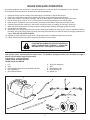
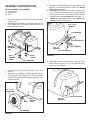
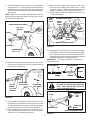
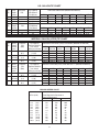
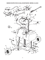
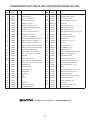
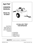
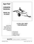
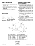
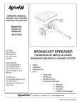
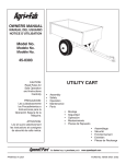
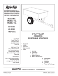
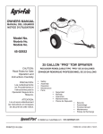
™
owners
manual
Model No.
45-0424
25 GALLON ATV
TOW SPRAYER
CAUTION:
Read Rules for
Safe Operation
and Instructions
Carefully
Assembly
Operation
Maintenance
Repair Parts
the fastest way to purchase parts www.speedepart.com
PRINTED IN USA
FORM NO. 40165 (REV. 2/07)
RULES FOR SAFE OPERATION
Any power equipment can cause injury if operated improperly or if the user does not understand how to operate
the equipment. Exercise caution at all times when operating equipment.
1.
2.
3.
4.
5.
6.
7.
8.
9.
Read this owners manual carefully before attempting to assemble or operate this sprayer.
Read your vehicle owners manual for operating and safety rules before using this equipment.
Never allow children to operate this sprayer, and do not allow adults to operate without proper instructions.
Do not allow anyone to ride on or sit on this sprayer. Do not allow passengers on the towing vehicle.
Keep the area of operation clear of all persons, particularly small children. Also keep area clear of pets.
Read the chemical label carefully for instructions and caution notes on handling and mixing of chemicals.
Wear eye and hand protection and wear protective clothing when handling and applying lawn chemicals.
Do not spray on windy days.
Attachment of this sprayer may affect your tractor's braking and stability. Be aware of your tractor's capabilities. Refer to
the safety rules in the vehicle owner's manual concerning safe operation on slopes. Be aware of changing conditions on
slopes. STAY OFF OF STEEP SLOPES.
10. Operate at reduced speed on rough terrain, along ditches and on hillsides to prevent loss of control.
11. Follow maintenance and lubrication instructions as outlined in this manual.
LOOK FORTHIS SYMBOLTO POINT OUT IMPORTANT
SAFETY PRECAUTIONS. IT MEANS — ATTENTION!
BECOME ALERT! YOUR SAFETY IS INVOLVED.
Your sprayer carton contains parts as shown below. The hardware package contains parts as shown on page 3.
Identify all parts before beginning assembly.
CARTON CONTENTS
LOOSE PARTS IN CARTON
1.
2.
3.
4.
5.
Lid
Tank
Return/Bypass Hose (may be assembled to tank)
Boom Assembly
Boom Mount Bracket
6. Spray Gun Assembly
7. Axle
8. Axle Support Tube
9. Hitch Brackets (2)
10. Wheels (2)
1
3
4
2
6
5
10
7
8
9
SHOWN FULL SIZE
A
B
C
G
F
D
E
H
I
K
J
L
M
NOT SHOWN FULL SIZE
N
O
R
Q
P
40
20
0
S
60
T
80
100
U
HARDWARE PACKAGE - FULL SIZE
KEY
QTY.
A
2
DESCRIPTION
KEY
QTY.
DESCRIPTION
Hex Bolt, 5/16" x 3"
L
2
Cotter Pin
B
2
Hex Bolt, 5/16" x 2-1/4"
M
2
Carriage Bolt, 5/16" x 1-1/4"
C
2
Hex Bolt, 5/16" x 2"
N
2
Screw, #10 x 3/8"
D
4
SEMS Nut, 5/16"
O
2
Knob
E
6
Nylock Nut, 5/16"
P
1
Spray Gun Clip, Small
F
6
Flat Washer, 5/16"
Q
1
Spray Gun Clip, Large
G
4
Flat Washer, 3/4"
R
1
Pressure Gauge
H
2
Lock Washer, #10
S
1
Coiled Hose Clamp
I
2
Washer, 5/16" Tooth Lock
T
2
Gasket, 3/4" Garden Hose
J
1
Hitch Pin
U
2
Axle Clamp
K
1
Hair Cotter Pin
ASSEMBLY INSTRUCTIONS
5. Fasten the front ends of the frame tubes together using
two 5/16" x 3" hex bolts and 5/16" nylock nuts. Do not
tighten yet. See figure 3.
6. Assemble hitch brackets to frame tubes using two 5/16"
x 2-1/4" hex bolts, four washers (one on each side) and
5/16" nylock nuts. Position each bolt behind a cross bolt
in the hitch arms. Do not tighten yet. See figure 3.
7. Tighten bolts assembled in step 7 then tighten bolts
assembled in step 8. See figure 3.
TOOLS REQUIRED FOR ASSEMBLY
(2) 1/2" Wrenches
(1) Screwdriver
(1) Pliers
1. Remove all items from carton and lay out as shown on
pages 2 and 3.
2. Assemble the axle clamps, axle support tube and four
5/16" SEMS nuts to the factory installed bolts in the
frame tubes. See figure 1.
5/16" x 2-1/4"
HEX BOLT
5/16" WASHER
5/16" NYLOCK NUT
FACTORY
INSTALLED
BOLT
AXLE
SUPPORT
TUBE
5/16" WASHER
5/16" x 3"
HEX BOLT
5/16" NYLOCK NUT
FIGURE 3
AXLE
CLAMP
5/16" SEMS NUT
8. Assemble the boom mount bracket to the rear of the
frame tubes using two 5/16" x 2" hex bolts and 5/16"
nylock nuts. See figure 4.
FIGURE 1
3. Slide the axle through the axle support tube. See
figure 2.
4. Assemble a 3/4" washer, a wheel (valve stem facing
out) and another 3/4" washer onto the axle. Assemble
a cotter pin through the end of the axle. Repeat on other
end. See figure 2.
1/8" x 1-1/2"
COTTER PIN
5/16" NYLOCK NUT
AXLE
5/16" x 2"
HEX BOLT
AXLE
SUPPORT
TUBE
FIGURE 4REAR VIEW
3/4" WASHER
FIGURE 2
9. Assemble the boom bars to the boom mount bracket
using two 5/16" x 1-1/4" carriage bolts, tooth lock washers
(between the bar and bracket), 5/16" flat washers and
knobs.The boom connecting hose should extend upward.
See figure 5.
NOTE: Make sure the nozzles are adjusted so that the
openings face straight down when the boom bar is in the
horizontal operating position.
13. Slide coiled hose clamp onto spray gun hose. Push
hose onto hose adapter on the side of the "T" fitting
as shown in figure 7. Tighten clamp around hose and
adapter. Snap spray gun into clips on side of tank.
14. Carefully screw the pressure gauge into the top of the
"T" fitting. See figure 7.
SPRAY
GUN
HOSE
BYPASS/RETURN HOSE
COILED
HOSE
CLAMP
BOOM CONNECTING HOSE
5/16" FLAT
WASHER
GARDEN
HOSE
GASKET
WASHER
(TOOTH LOCK)
KNOB
PRESSURE
GAUGE
BOOM CONNECTING HOSE
BOOM BAR
FIGURE 7
CARRIAGE BOLT
5/16" x 1-1/4"
15. Attach sprayer to tractor hitch and connect the wiring to
tractor battery. Red wire must be connected to positive
post on battery or to "HOT" connection on a tractor switch
or ammeter. Brown wire may be grounded or connected
to negative battery post. See figures 8 and 9.
IMPORTANT: This sprayer should be connected to 12 volt batteries only!
FIGURE 5
10. Assemble the large and small spray gun clips to the
side of the tank using two #10 x 3/8" screws and #10
lock washers. See figure 6.
IN LINE SWITCH
RED
QUICK COUPLER
+
RED
BATTERY
BROWN
BROWN
FIGURE 8
#10 x 3/8"
SCREW
SPRAY GUN
CLIP (LARGE)
SPRAY GUN
CLIP (SMALL)
#10 LOCK
WASHER
NEVER ALLOW NEGATIVE PIN ON PLUG
TO COME IN CONTACT WITH POSITIVE
"HOT" POST ON BATTERY. FIRE OR
EXPLOSION MAY RESULT!
PLUG
FIGURE 6
11. Insert a garden hose gasket into the swivel nut on the
bypass/return hose. Screw nut onto upper outlet of the
"Y" valve fitting. Place the other end of the hose down
through the hole at the rear of the tank. See figure 7.
12. Insert a garden hose gasket into the swivel nut on the
boom connecting hose. Screw the nut onto the lower
outlet of the "Y" valve fitting. See figure 7.
NEGATIVE PIN
+
POSITIVE
"HOT"
POST
NEGATIVE
POST
12 VOLT TRACTOR BATTERY
FIGURE 9
OPERATION
USING THE SPRAYER
1. Determine the application rate (gallons per 1,000
sq. feet or gallons per acre) based on the chemical
manufacturers recommendations. Use this rate to help
select the pressure setting and tractor speed in the
following instructions.
BEFORE STARTING
It is important to test the boom and spray gun with plain
water before using chemicals. This will enable you to check
the sprayer for leaks and to set the spray pattern and nozzle
pressure. If a leak should occur, thread tape may be used
to better seal the fitting.
2. Determine the approximate square footage of the area to
be sprayed and estimate the number of gallons required.
This can help avoid unneeded solution left in the tank.
ON-OFF SWITCH
This switch is connected in line to the wiring assembly and
is used by the operator to turn the pump motor on or off.
3. Determine the appropriate speed at which to travel, based
on the chosen pressure setting and the recommended
application rate. Use the tip chart on page 9.
PUMP PRESSURE SWITCH
The pump is equipped with a pressure switch. The pressure
switch senses outlet pressure of the pump and will turn off
the electrical power to the pump at a predetermined high
pressure point (60 PSI). If the flow demand is very low, the
pump may reach this high pressure point and the switch will
cause "cycling" (the pump cycles on and off rapidly). This is
not a problem unless the pump is subject to continuous cycling
within one second intervals for long periods of time.
4. To determine the throttle setting for attaining the
appropriate speed, mark off 100, 200 and 300 feet
intervals. The speed chart at the bottom of page 9
indicates the number of seconds it takes to travel these
distances. Set the throttle and, with a running start, travel
the distances in the number of seconds indicated by
the speed chart. Once you have determined the throttle
and gear settings needed, mark the throttle location
so that you can easily resume the same speed after
stopping.
ADJUSTING OPERATING PRESSURE
The sprayer is equipped with a "Y" fitting containing a bypass
valve and a boom valve. The bypass valve controls the flow
to the return (bypass) hose. The amount of flow through the
return hose determines the operating pressure when the
boom or the spray gun is in use. Adjust the bypass valve
while either the boom or the spray gun is in use to obtain
the desired pressure, indicated by the pressure gauge. The
tip chart on page 9 shows how different pressure settings
affect boom application rates.
5. Set the operating pressure. Spray with plain water to
help determine the best setting. For best results stay
in the 20 to 30 PSI range. (At 10 PSI the spray pattern
begins to break up, at 40 PSI some drift develops.) Refer
to the tip chart on page 9.
6. Add the chemical solution to the tank, following the
product instructions.
7. Drive to the starting place for spraying. Set the boom
in position for spraying. Set the throttle at the position
determined in step 4. Flip the sprayer's in-line switch to
the "ON" position to start spraying.
ON-OFF ADJUSTMENT OF BOOM NOZZLES
The boom valve on the "Y" fitting controls flow to the boom
nozzles. It should be either completely open or completely
closed. The boom operating pressure can be controlled
using the bypass valve on the "Y" fitting.
8. Stay clear of flowers, shrubs and evergreen trees when
spraying weed control solutions to prevent contact of
the solution with these sensitive plants.
ADJUSTING SPRAY GUN NOZZLE
Turn the nozzle on the spray gun to adjust the spray from
a cone shaped fine mist to a straight stream. Control the
spray gun operating pressure with the bypass valve on the
"Y" fitting. Maximum spray gun pressure can be attained
when the boom is shut off.
SETTING THE BOOM FOR SPRAYING
The correct positioning of the boom places the nozzles
approximately 40" apart and 14" above the ground. This
gives a spray width of approximately 80" with a slight center
overlap. See figure 10.
a. Slide the boom bars out to the ends of the
slots.
b. Swivel the boom bars until the nozzles are
approximately 14" above the ground.
c. Make sure the nozzles are adjusted so that the openings point straight down.
CAUTION: WEAR EYE PROTECTION,
GLOVES AND PROTECTIVE CLOTHING
WHEN HANDLING AND WORKING WITH
LAWN CHEMICALS.
40"
14"
80"
FIGURE 10
MAINTENANCE
ATTENTION!
1. Do not store sprayer with any solution left in tank.
Do not allow chemicals to sit in pump for extended times
of idleness. Some chemicals will damage the pump
valve if allowed to soak untreated for a length of time.
Always flush the pump with water after each use. Follow
the procedures in the AFTER EACH USE instructions
for flushing and disposal.
2. Periodically clean the strainer in the end of the intake
hose at the bottom of the tank. Remove the nylon swivel
nut from the hose, pull out the screen and flush it with
clear water.
3. Periodically clean the strainers in the boom nozzles.
Remove the nozzle, pull out the screen and flush it with
clear water.
WINTER STORAGE
6. Drain all water out of the sprayer, paying special
attention to the pump and handgun. These items are
especially prone to damage from chemicals and freezing
weather.
AFTER EACH USE
4. After use, fill the sprayer part way with water, start the
sprayer and allow clear water to be pumped through the
plumbing system and out through the boom assembly
and the handgun. Use the handgun to thoroughly wash
all internal parts of the tank, the outside of the tank and
the boom.
7. The sprayer should be winterized before storage by
pumping a 50-50 solution of water and R. V. antifreeze
through the entire plumbing. Proper care and
maintenance will prolong the life of the sprayer.
5. Refill the tank about half full with plain water and a
chemical neutralizer and repeat the cleaning instructions
above. Flush the entire sprayer with the neutralizing
agent. Follow the chemical manufacturers instructions
for disposal of all wash or rinsing water.
U.S. GALLON TIP CHART
Tip Spray
Pressure
No. Height
PSI
Inches
10
#3
13"
20
30
Tip Capacity
US Gallons
Per Minute
1 MPH
.30
44.2
.42
63
.52
76.8
GALLONS PER ACRE (BASED ON WATER)
Tip Spray
Pressure
No. Height
PSI
Inches
10
#3
13"
20
30
Tip Capacity
US Gallons
Per Minute
1 MPH
.30
1.0
.42
1.4
.52
1.8
GALLONS PER 1000 SQ. FT. (BASED ON WATER)
2 MPH
22.1
31.5
38.4
2 MPH
0.50
0.72
0.88
3 MPH
14.8
20.9
25.8
3 MPH
0.34
0.48
0.59
4 MPH
11.1
15.7
19.3
4 MPH
0.26
0.35
0.44
5 MPH 7.5 MPH 10 MPH
8.9
5.9
4.4
12.6
8.4
6.3
15.4
10.3
7.7
5 MPH 7.5 MPH 10 MPH
0.20
0.14
0.10
0.29
0.19
0.14
0.35
0.24
0.18
IMPERIAL GALLON (LITER) TIP CHART
IMPERIAL GALLONS (Liters) PER ACRE (BASED ON WATER)
Tip Spray
Pressure
No. Height
PSI
Inches
(Bar)
(mm)
10
(0.7)
#3
13"
20
(330 mm)
(1.4)
30
(2.1)
Tip Capacity
Imperial Gallons
per minute
(liters per minute)
.25
(1.135)
.35
(1.59)
.433
(1.97)
Tip Spray
Pressure
No. Height
PSI
Inches
(Bar)
(mm)
10
(0.7)
#3
13"
20
(330 mm)
(1.4)
30
(2.1)
IMPERIAL GALLONS (Liters) PER 1000 SQ. FT. (BASED ON WATER)
Tip Capacity
Imperial Gallons
per minute
1 MPH 2 MPH 3 MPH 4 MPH 5 MPH 7.5 MPH 10 MPH
(liters per minute) 1.6 K/H 3.2 K/H 4.8 K/H 6.4 K/H 8 K/H 12 K/H 16 K/H
.25
0.85
0.42
0.28
0.21
0.17
0.11
0.08
(1.135)
(3.85)
(1.92)
(1.29)
(0.97)
(0.77)
(0.51)
(0.38)
.35
1.21
0.60
0.40
0.30
0.24
0.16
0.12
(1.59)
(5.48)
(2.74)
(1.82)
(1.37)
(1.10)
(0.73)
(0.55)
.433
1.47
0.74
0.49
0.37
0.29
0.20
0.15
(1.97)
(6.68)
(3.34)
(2.24)
(1.68)
(1.34)
(0.90)
(0.67)
1 MPH 2 MPH 3 MPH 4 MPH 5 MPH 7.5 MPH
1.6 K/H 3.2 K/H 4.8 K/H 6.4 K/H 8 K/H
12 K/H
36.8
18.4
12.3
9.2
7.4
4.9
(167.3) (83.6)
(56.0)
(42.0)
(33.7)
(22.3)
52.5
26.2
17.4
13.1
10.5
7.0
(238.5) (119.2) (79.1)
(59.4)
(47.7)
(31.8)
64.0
32.0
21.5
16.1
12.8
8.6
(290.7) (145.3) (97.7)
(73.1)
(58.3)
(39.0)
GROUND SPEED CHART
M.P.H. (K/H)
1.0 (1.6)
2.0 (3.2)
3.0 (4.8)
4.0 (6.4)
5.0 (8.0)
6.0 (9.7)
7.0 (11.3)
8.0 (12.9)
9.0 (14.5)
10.0 (16.1)
Time Required in Seconds to
Travel a Distance of:
100 ft (30.5 M) 200 ft (61 M) 300 ft (91.5 M)
68
34
23
17
14
11
9.7
8.5
7.6
6.8
136
68
45
34
27
23
19
17
15
14
205
102
68
51
41
34
29
26
23
20
10 MPH
16 K/H
3.7
(16.7)
5.2
(23.8)
6.4
(29.1)
NOTES
REPAIR PARTS FOR 25 GALLON SPRAYER MODEL 45-0424
35
63
55
22
7
21
B
35
33
30
34
36
37
30
21
63
57
21
33
34
37
32
51
36
21 63
21
40
31
C
59
21
19
53
58
55
8
7
15
62
6
18
55
9
10
17
B
61
16
A
54
A
2
20
14
62
4
15
3
29
64
50
48
1
60
13
48 47
50
5
7
C
28
38
49
65
42
56
41
28
44
27
51
24
52
26
40
23
44
46
26
25
11
51
39
45
10
40
43
REPAIR PARTS LIST FOR 25 GALLON SPRAYER MODEL 45-0424
REF
NO.
PART
NO.
QTY. DESCRIPTION
REF
NO.
PART
NO.
1
46283
1
2
45015
1
3
46278
4
5
QTY. DESCRIPTION
Tank (25 Gal.)
33
45028
2
Nozzle, SS Floodjet
Pump and Motor
34
45029
2
Strainer, Screen Type
1
Hose, 1/2" ID (24" Lg.)
35
45037
2
Nut, Screen Body
45021
1
Hose, 1/2" ID (20" Lg.)
36
47396
2
Elbow, Plastic 11/16" Thd.
45024
1
Strainer, Cap Type 1"
37
726-0178
2
Nylon Tie
6
45031
1
Adapter, 1/2" NPT x Hose
38
44180
2
Bolt, Hex 5/16-18 x 2"
7
45032
3
Nut, Swivel 3/4" Garden Hose
39
46782
2
Bolt, Hex 5/16-18 x 3"
8
45033
1
Hose Barb, 1/2"
40
47810
6
Nut, Nylock 5/16-18
9
45069
4
Screw, Ph. Pan Hd. 10-24 x 1"
41
44947
4
Bolt, Curved Head 5/16-18 x 1-5/8"
10
43910
4
Flat Washer, #10 SAE
42
43086
4
Lock Washer, 5/16"
11
46980
4
Nut, Hex 5/16-18 (SEMS)
43
43343
1
Pin, Hair Cotter #4 (1/8")
12
45085
2
Terminal, .25 Male Tab (not shown)
44
43009
4
Washer, 3/4"
13
46276
1
Adapter, 3/4" GH x 1/2" Barb
45
43093
2
Cotter Pin, 1/8" x 1-1/2"
14
46277
1
Elbow, 3/8 NPT x 1/2" Barb
46
47623
1
Hitch Pin
15
45025
2
Clamp, 1/2" Hose (For Black Hose)
47
45180
1
Hose Clip, Small
45026
2
Clamp, 3/8" Hose (For Clear Hose)
48
736-0722
2
Lock Washer, #10
16
49754
1
Switch and Wire Assembly
49
44695
4
Washer, Bowed
17
45049
1
Nipple, (Nylon) 1/2" x 3/8" Red.
50
46677
2
Screw, Phillips Hd. #10-24 x 3/8"
18
45050
1
Tee, 1/2" x 1/2" x 1/2" (1/4" Port)
51
43081
6
Washer, 5/16" Std. Wrt.
19
47406
1
Spray Gun
52
25897
1
Axle Support Tube
20
49761
1
Hose, 1/4" ID (15' Lg)
53
45017
1
Hose "Y" W / Valves 3/4"
21
45026
6
Clamp, 3/8" Hose (For Black Hose)
54
45071
1
Gauge, Pressure 2" 100 PSI
47405
6
Clamp, 1/4" Hose (For Clear Hose)
55
45072
3
Gasket, 3/4" Garden Hose
22
45034
1
Hose Barb, 3/8"
56
43085
4
Bolt, Hex 5/16-18 x 1-1/2"
23
40166
1
Frame Tube (RH)
57
712-0421
2
Knob
24
40167
1
Frame Tube (LH)
58
43682
2
Bolt, Carriage 5/16-18 x 1-1/4"
25
24192
2
Hitch Bracket
59
44732
2
Washer, Tooth Lock 5/16"
26
25896
2
Axle Clamp
60
47397
1
Hose Clip (Large)
27
25898
1
Axle
61
47390
1
Adapter, 1/2" NPT x 1/4" Barb
28
48511
2
Wheel
62
49779
2
Clamp, Coiled Hose
29
46700
1
Lid
63
47392
3
Hose, 3/8" ID (20" Lg.)
30
24122
2
Boom Bar
64
48719
1
Drain Cap
31
24585
1
Bracket, Boom Mount
65
43224
2
Bolt, Hex 5/16-18 x 2-1/4"
32
47394
1
Tee, Plastic 3/8" Hose
40165
1
Owners Manual
the fastest way to purchase parts www.speedepart.com
11
the fastest way to purchase parts www.speedepart.com
© 2006 Agri-Fab, Inc.
REPAIR PARTS
Agri-Fab, Inc.
809 South Hamilton
Sullivan, IL. 61951
217-728-8388
www.agri-fab.com