1
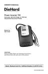
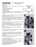
OWNER’S MANUAL
®
Power Inverter 140
Converts 12V DC Power to 110V AC
Household Electrical Power
Model No.
200.71491
CAUTION:
Read all Safety Rules and Operating Instructions,
and follow them with each use of this product.
Sears, Roebuck and Co., Hoffman Estates, IL 60179 U.S.A.
00-99-000591/1205
table of contents
Warranty............................................................................ 3
Important Safety Instructions............................................ 3
Power Inverter 140 Product Features............................... 5
Before Using Power Inverter 140...................................... 6
Operating Instructions....................................................... 7
Power Source.................................................................... 8
Usage Examples............................................................... 8
LED Indicator and Overload Protection............................ 9
Troubleshooting............................................................... 10
Specifications...................................................................11
Replacement Parts...........................................................11
Please read this Owner’s Manual before using your
Power Inverter 140.
For information about troubleshooting, call toll-free from anywhere in the U.S.A. 7 am to 4:30 pm Central Time Monday
through Friday. 1-800-SEARS-64 (1-800-732-7764).
WARRANTY
One-Year Full Warranty on DieHard Power Inverter 140
If this Power Inverter 140 fails due to a defect in material or workmanship within one year from the date of purchase, RETURN
IT TO ANY SEARS STORE or OTHER DIEHARD OUTLET IN
THE UNITED STATES FOR FREE REPLACEMENT.
This warranty gives you specific legal rights, and you may
also have other rights which vary from state to state.
Sears, Roebuck and Co., Dept. 817WA, Hoffman Estates,
IL 60179
important safety INSTRUCTIONS
save these instructions
Before using your Power Inverter 140, read and understand
this Owner’s Manual.
• Keep the inverter well ventilated in order to properly disperse heat generated while it is in use. Make sure there
are several inches of clearance around the top and sides
and do not block the slots of the inverter.
• Make sure the inverter is not close to any potential source
of inflammable fumes, gases or clothing.
• Keep the inverter dry.
• DO NOT allow it to come into contact with rain or moisture.
• DO NOT operate the inverter if you, the inverter, the device
being operated or any other surfaces that may come in
contact with any power source are wet. Water and many
other liquids can conduct electricity, which may lead to
serious injury.
• Do not place the inverter on or near heating vents, radiators or other sources of heat.
• Do not place the inverter in direct sunlight. The ideal air
temperature for operation is between 50° and 80°F.
• Do not use near open engine compartment.
• Only connect the power inverter to a 12-volt battery accessory outlet. Make sure the AC plug connection is tight.
• Do not modify the AC receptacle in any way.
• Use only 15-amp fuses.
POWER INVERTER 140 PRODUCT FEATURES
3
4
1
4
2
1. Green LED Indicator
2. One, 3-prong AC Receptacle
3. Positive Connector
4. Two, Negative Connectors
Before Using Power Inverter 140
It is important to know the continuous wattage of the device
you plan to use with the inverter. The Power Inverter 140
must be used with devices drawing 140 watts or less. If the
wattage is not marked on the device, an estimate can be
made by multiplying the AC input current (Amps) by the AC
voltage (110V).
Devices like TVs, fans or electric motors require additional
power to start (commonly known as the “starting or peak
power”). The Power Inverter 140 can supply a momentary
surge in wattage; however even devices rated less than the
maximum 140 watts can exceed the inverters surge capability and cause an automatic overload shutdown.
Make sure the device you are using is compatible with a
modified sine wave inverter.
OPERATING INSTRUCTIONS
1. Push the Power Inverter 140 firmly into the 12V
accessory outlet. The LED indicator light should glow
GREEN verifying the inverter is receiving power. (If
connecting in a vehicle, remove the cigarette lighter from
its outlet.)
2. Make sure that the device to be operated is turned
OFF.
3. Plug the device into the Power Inverter 140 AC outlet.
4. Turn the device on. If the LED Indicator briefly blinks
when you first plug the inverter in, it is a sign that there
is a short circuit within the power supply. Remove the
12-volt plug from the 12-volt accessory outlet. Firmly
reinsert the plug. If this does not remedy the problem,
try using a different 12-volt accessory power outlet.
Note: A ‘’buzzing’’ sound emitted from inexpensive
sound systems is the result of ineffective filters in the
sound system. This can be resolved by purchasing a
sound system with a higher quality power supply or
higher quality filter.
POWER SOURCE
Your average automobile or marine battery at full charge
will provide an ample power supply to the inverter for approximately 3 hours when the engine is off. The actual length
of time the inverter will function depends on the age and
condition of the battery and the power demand being placed
by the device being operated with the inverter.
Turn OFF the device plugged into the inverter before starting the engine. To maintain battery power, run the engine
every 2 to 3 hours for approximately 10 minutes to recharge
the battery. While the Power Inverter 140 draws very low
amperage when not in use and it should be unplugged to
avoid battery drain.
USAGE EXAMPLES
Device Type
Estimate Wattage
Cell Phones, MP 3 Players
10 watts
Portable CD
50 watts
Laptop Computers
90 watts
Video Games
100 watts
LED INDICATOR and OVERLOAD PROTECTION
The LED glows GREEN automatically when plugged into
a 12V DC source and will not glow under the following
conditions:
1. When the power input from the vehicle’s battery drops
to approximately 10 volts, low battery shutdown occurs
and inverter shuts off.
2. When the power input the vehicle’s battery exceeds 15
volts, high voltage overload protections occurs.
3. The continuous load demand from the equipment or
device being operated exceeds 140 watts.
4. The case temperature become hot (exceeds 145°F).
Reset:
To reset after shutdown occurs, check the source of the
problem and correct. Reinsert the inverter into the 12V accessory outlet.
TROUBLESHOOTING
PROBLEM: Low or No Output Voltage
Reason/Solution
1. Poor contact at terminals.
Unplug and reinsert Power Inverter 140.
2. Equipment being operated is drawing too much
power.
Use a higher capacity inverter or do not use the
device.
3. Inverter is too hot (thermal shut down).
Allow inverter to cool. Check for adequate ventilation. Reduced the load on the inverter to rated
continuous power output.
4. Fuse blows
A blown fuse is usually caused by reverse polarity
or a short circuit within the device being operated.
To replace:
• Disconnect the device immediately.
• Find the source of the problem, and repair it.
• Install a new 15-amp fuse. Do not tighten the fuse
cap too far; finger tight is sufficient.
Note: Installing a fuse higher than 15-amps may
cause damage to the inverter.
5. Inverter may be defective.
Call 1-800-SEARS-64 (1-800-732-7764) for troubleshooting assistance, or return it to any Sears store
or other DieHard outlet in the United States for a
free replacement. 10
SPECIFICATIONS
Maximum Continuous Power...............................140 Watts
Surge Capacity (Peak Power)..............................280 Watts
No Load Current Draw........................................<0.2 Amps
Wave Form........................................... Modified Sine Wave
Input Voltage Range.................................. 10.5 – 15.5V DC
Low Battery Alarm......................................................... N/A
Output Voltage............................................. 110 – 125V AC
Low Battery Shutdown.............................. 9.9V – 10.8V DC
High Battery Shutdown........................... 15.0V – 16.0V DC
Optimum Efficiency.....................................................>85%
AC Receptacles.............................One, NEMA 5-15 (USA)
Dimensions...........................................5”H x 2.5”W x 1.5”D
Product Weight................................. Approximately .45 lbs.
AC Outlets................................................ 110V AC 3-Prong
Fuse..............................................................15 Amp (250V)
REPLACEMENT PARTS
Fuse - 15 Amp (250V)
Can be purchased at most electronic component retailers.
11
12