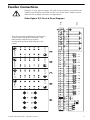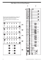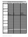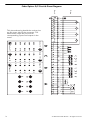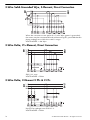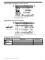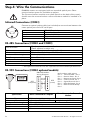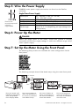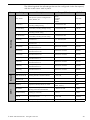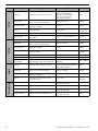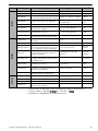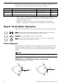
1
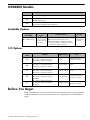
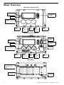
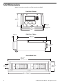
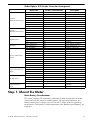
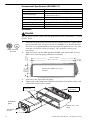
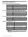
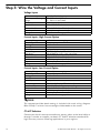
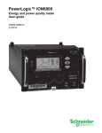
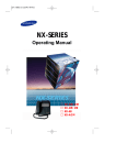
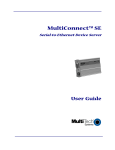
PowerLogic® ION8800 Energy & Power Quality Meter Installation Guide 05/2007 Danger This symbol indicates the presence of dangerous voltage within and outside the product enclosure that may constitute a risk of electric shock, serious injury or death to persons if proper precautions are not followed. Caution This symbol alerts the user to the presence of hazards that may cause minor or moderate injury to persons, damage to property or damage to the device itself, if proper precautions are not followed. Consult this document whenever this symbol is used on the meter, to determine the nature of the potential hazard and any actions which need to be taken. Note This symbol directs the user’s attention to important installation, operating and maintenance instructions. Installation Considerations Installation and maintenance of the ION 8800 meter should only be performed by qualified, competent personnel that have appropriate training and experience with high voltage and current devices. The meter must be installed in accordance with all local and national electrical codes. If this equipment is used in a manner not specified by the manufacturer, the protection from electric shock, fire, etc. provided by this equipment may be impaired. DANGER Failure to observe the following instructions may result in severe injury or death. During normal operation of the ION 8800 meter, hazardous voltages are present on its connector pins, and throughout the connected potential transformer (PT), current transformer (CT), direct connect without PTs, digital (status) input, control power and external I/O circuits. PT and CT secondary circuits are capable of generating lethal voltages and currents with their primary circuit energized. Follow standard safety precautions while performing any installation or service work (i.e. removing PT fuses, shorting CT secondaries, etc). Do not use digital output devices for primary protection functions. These include applications where the devices perform energy limiting functions or provide protection of people from injury. Do not use the ION 8800 in situations where failure of the devices can cause injury or death, or cause sufficient energy to be released that can start a fire. The meter can be used for secondary protection functions. The ION 8800 meter’s chassis ground must be properly connected to a good earth ground for safety, and for the noise and surge protection circuitry to function correctly. Failure to do so will void the warranty, and create a risk of electric shock, injury or death. When installing the meter, all voltage paths (measurement voltage and all auxiliary circuits such as the power supply and the tariff control voltage) must be fused according to applicable local safety standards. CAUTION Observe the following instructions, or permanent damage to the meter may occur. The ION 8800 meter offers a range of hardware options that affect input ratings. The ION 8800 meter’s serial number label lists all equipped options. Applying current levels incompatible with the current inputs will permanently damage the meter. This document provides installation instructions applicable to each hardware option. Do not HIPOT/Dielectric test the digital (status) inputs, digital outputs, power supply terminals or communications terminals. Refer to the label on the ION 8800 meter for the maximum voltage level the device can withstand. Replacing the meter battery with the wrong type or voltage rating could result in damage to the meter. Use only a lithium LiSOCl2 battery with a rated voltage of 3.6 V, and the same construction as the original battery, as a replacement. 3 Network Compatibility Notice for the Internal Modem The internal modem in meters equipped with this option is compatible with the telephone systems of most countries in the world. Use in some countries may require modification of the internal modem’s initialization strings. If problems using the modem on your phone system occur, please contact Schneider Electric Technical Support. Standards Compliance Made by Power Measurement Ltd. PowerLogic, ION, ION Enterprise, MeterM@il and Modbus are either trademarks or registered trademarks of Schneider Electric. Covered by one or more of the following patents: U.S. Patent No's 7010438, 7006934, 6990395, 6988182, 6988025, 6983211, 6961641, 6957158, 6944555, 6871150, 6853978, 6825776, 6813571, 6798191, 6798190, 6792364, 6792337, 6751562, 6745138, 6737855, 6694270, 6687627, 6671654, 6671635, 6615147, 6611922, 6611773, 6563697, 6493644, 6397155, 6236949, 6186842, 6185508, 6000034, 5995911, 5828576, 5736847, 5650936, D505087, D459259, D458863, D443541, D439535, D435471, D432934, D429655, D427533. 4 ION8800 Models Feature Set Description C Basic Tariff/Energy revenue meter B Feature Set C + EN50160 and IEC 61000-4-30 Class A compliant power quality monitoring A Feature Set B + power quality analysis (waveforms and transient capture with 1024 samples/cycle resolution) Available Options Logging and Recording Current Inputs 5 MB memory 10 MB memory Low Current (In=1A, 2A) High Current (In=5A) Communications Security Optical IEC 1107 RS-485 and optical IEC 1107 Communications Module (RS-485, Standard Hardware locked RS-232, modem, 10-Base-T Ethernet, 10-Base-FL Fiber Ethernet) I/O Options Ordering Code Outputs A 8 digital Form A solid-state outputs 1 Form C mechanical relay 4 Form C solid-state outputs None One RS-485 port on Essailec connector B 8 digital Form A solid-state outputs 1 Form C mechanical relay 4 Form C solid-state outputs 3 Low voltage None C 8 digital Form A solid-state outputs 1 Form C mechanical relay 4 Form C solid-state outputs 3 High voltage None D 1 Form C mechanical relay 4 Form C solid-state outputs Digital Inputs 3 Low voltage One RS-485 port on Essailec connector 3 High voltage One RS-485 port on Essailec connector IRIG-B E 1 Form C mechanical relay 4 Form C solid-state outputs IRIG-B Com Before You Begin Before installing the meter, familiarize yourself with the steps in this guide and read the safety precautions presented on the “Installation Considerations” page. © 2007 Schneider Electric. All rights reserved. 5 Meter Overview Meter Front (Cover Closed) Operational LEDs Navigation Buttons Display Optical Communications Port Slot-head Screw varh Pulsing Port Cover Seal Wh Pulsing Port Slot-head Screw Meter Front (Cover Open) Sealed Buttons Operational LEDs Navigation Buttons Display Battery Cover Optical Communications Port Slot-head Screw varh Pulsing Port Cover Seal Wh Pulsing Port Slot-head Screw Meter Back Communications Module Cover Plate Essailec Connector 6 Ground Terminal © 2007 Schneider Electric. All rights reserved. Front Panel Button Functions ALT/ENTER: Press this button once to enter ALT mode. Press and hold to enter Setup mode. In Setup mode, press this button to accept changes. Press the UP / DOWN arrow buttons to highlight menu items, or increment / decrement numbers. Press and hold to shift cursor left and right. NAVIGATION: DEMAND RESET: Press this button to reset all maximum demand registers. Not accessible when cover is sealed. TEST MODE: Press this button to enter Test Mode. Billable quantities do not accumulate when meter is in Test Mode. Not accessible when cover is sealed. ALT CONFIG: Press this button to enter the Alternate Configuration menu. Not accessible when cover is sealed. Press this button to reset meter quantities. Not accessible when cover is sealed. MASTER RESET: This button is not currently implemented. Not accessible when cover is sealed. SPARE: Meter Labels Front of Meter (Cover Closed) Voltage and Current Ratings Transformer Factors and Energy Pulse Weight Factors Removable User Label Nameplate Removable User Label Removable User Labels Insert user labels between bezel label and plastic lid while cover is open. 50.0 mm (1.97“) 13.0 mm (0.51“) 60.0 mm (2.36“) 44.0 mm (1.73“) © 2007 Schneider Electric. All rights reserved. 7 Unit Dimensions Meter dimensions conform to DIN standard 43862. Front View of Meter 132.2 mm (5.21“) 4.6 mm (0.18“) 190.5 mm (7.50“) M3 Thread Screw 202.1 mm (7.96“) 38.4 mm (1.51“) Side View of Meter 260.0 mm (10.24“) 111.8 mm (4.40“) Front of Rack View 482.0 mm (18.98“) to fit 19 inch rack 132.5 mm (5.22“) 3U high 57.2 mm (2.25“) 461.0 - 469.0 mm (18.15 - 18.46“) 8 © 2007 Schneider Electric. All rights reserved. Essailec Connections Voltage, current, power supply, I/O and communication connections are made via the Essailec connector on the rear of the meter. Meters can be ordered with multiple connector configurations. Order Options B/C Circuit & Pinout Diagrams Meter Rack This pinout drawing details the various pins on the meter side of the connector. The table below maps the pins to their corresponding inputs and outputs in the meter. E D C Code 13 B Code 01 Code 15 Code 03 Code 17 Code 05 Code 13 Code 07 A © 2007 Schneider Electric. All rights reserved. 9 Order Option A Circuit & Pinout Diagrams Meter Rack This pinout drawing details the various pins on the meter side of the connector. The table below maps the pins to their corresponding inputs and outputs in the meter. E D C Code 13 B Code 01 Code 15 Code 03 Code 17 Code 05 Code 15 Code 07 A 10 © 2007 Schneider Electric. All rights reserved. Order Options A/B/C Essailec Connector Arrangement Meter Port Current Measurement Inputs Voltage Measurement Inputs Form A Outputs Form C Solid-state Relays Unused Form A Outputs Form C Mechanical Relay Digital Inputs or RS-485 Com Power Supply Inputs (AC/DC) I11 I12 I21 I22 I31 I32 I41 I42 Uref U1 U2 U3 DO7 & DO8 K DO5 & DO6 K DO5 DO6 DO7 DO8 DO1 & DO2 K DO1 DO1 DO2 DO2 DO3 & DO4 K DO3 DO3 DO4 DO4 DO11 & DO12 K DO9 & DO10 K DO9 DO10 DO11 DO12 Alarm K Alarm Alarm DI-SCOM (or RS-485 Shield) DI1 (or RS-485 +) DI2 (or RS-485 -) DI3 (or unused) Power Supply N/Power Supply L/+ © 2007 Schneider Electric. All rights reserved. Essailec Connector Pin Description A01 A1 A02 A2 A03 A3 A04 A4 B0 B1 B2 B3 B4 B5 B6 B7 B8 B9 C0 C1 C2 C3 C4 C5 C6 C7 C8 C9 D0 D1 D2 D3 D4 D5 D6 D7 D8 D9 E0 E1 E2 standard standard standard standard standard standard optional optional standard standard standard standard standard; Common standard; Common standard; NO standard; NO standard; NO standard; NO standard; Common standard; NO standard; NC standard; NO standard; NC standard; Common standard; NO standard; NC standard; NO standard; NC Unused Unused Unused Unused standard; Common standard; Common standard; NO standard; NO standard; NO standard; NO standard; Common standard; NO standard; NC E5 standard; Common E6 E7 E8 E3 E4 E9 RS-485 + RS-485 standard Unused Power Supply neutral (-) Power Supply line (+) 11 Order Options D/E Circuit & Pinout Diagrams Meter Rack This pinout drawing details the various pins on the meter side of the connector. The table below maps the pins to their corresponding inputs and outputs in the meter. D C Code 15 B Code 05 Code 15 Code 03 Code 15 Code 07 A 12 © 2007 Schneider Electric. All rights reserved. Order Options D/E Essailec Connector Arrangement Meter Port Current Measurement Inputs Voltage Measurement Inputs Digital Inputs Power Supply Inputs (AC/DC) Form C Solid-state Relays Form C Mechanical Relay RS-485 Com IRIG-B Clock Synchronization Input Essailec Connector Pin I11 I12 I21 I22 I31 I32 I41 I42 Uref U1 U2 U3 DI-SCOM DI1 DI2 DI3 Power Supply N/Power Supply L/+ DO1 & DO2 K DO1 DO1 DO2 DO2 DO3 & DO4 K DO3 DO3 DO4 DO4 Alarm K Alarm Alarm RS-485 Shield RS-485 + RS-485 - A01 A1 A02 A2 A03 A3 A04 A4 B0 B1 B2 B3 B5 B6 B7 B8 B4 B9 C0 C1 C2 C3 C4 C5 C6 C7 C8 C9 D0 D1 D2 D3 D5 D6 D7 D8 IRIG-B input common D4 IRIG-B input D9 Description standard standard standard standard standard standard optional optional standard standard standard standard standard; Common standard standard standard Power Supply neutral (-) Power Supply line (+) standard; Common standard; NO standard; NC standard; NO standard; NC standard; Common standard; NO standard; NC standard; NO standard; NC standard; Common standard; NO standard; NC Unused RS-485 Shield RS-485 + RS-485 Unused optional; clock synch input Common optional; clock synch input Step 1: Mount the Meter Meter Battery Considerations The meter’s battery life expectancy depends on both temperature and the amount of time the meter is without power. For typical installations, the battery should last 10 years minimum at 25ºC meter ambient operating temperature. The battery is field replaceable (see “Replacing the Battery” on page 31). © 2007 Schneider Electric. All rights reserved. 13 Environmental Specifications (IEC62052-11) Mounting Location Metrological Operating Range Max. Altitude Display Operating Range Storage Range Relative Humidity Range Enclosure Rating Indoor use -10 to +45ºC (14 to +113ºF) -25 to +55ºC (-13 to +131ºF) No formation of ice 2000 metres (6562 feet) above sea level -10 to +60ºC (14 to +140ºF) -25 to +70ºC (-13 to +158ºF) 5 to 95% non-condensing IP51 (IEC60529) Installation DANGER Do not power up the meter until the ground terminal is connected -- risk of electric shock. Connect the ground terminal on the rear of the meter to a good earth ground on the rack, using a 3.3 mm2 (12 AWG) wire. Ensure that the terminal nut is tightened down securely onto the ground wire. The wire must be a minimum of 30 cm long (11.8”) to allow racking and unracking. 2. Slide the meter into the DIN standard 43862 rack (half-width 19 inch/ 482.6 mm rack with plug-in Essailec connector). 133 mm (5.24”) 57.1 mm (2.25”) 37.9 mm (1.49”) Meter Ground Terminal 1. 465 mm (18.31”) 451 mm (17.76”) 7 mm (0.28”) Cut-out for 482.6 mm (19”) Chassis M6 3. Ensure the rear connector fits tightly. 4. Tighten the 2 slot-head screws (M3 thread) into the front of the meter rack, to hold the meter firmly in place. Meter Essailec Connector Rack Essailec Connector ION8800 Meter Slot-head Screws 14 482.6 mm (19”) Rack © 2007 Schneider Electric. All rights reserved. Step 2: Wire the Digital I/O Form C Digital Output: Mechanical Alarm Relay Contacts Max. Switching Voltage Max. Switching Current Operate Time (max.) Release Time (max.) Isolation to Ground Rating Minimum Operations common, NO, NC 250 VAC/125 VDC (internally limited to 300 V peak) 1 A AC/0.1 A DC 8 ms 4 ms 2,000 VAC for 60 s (50 Hz) Installation category II (local), Pollution degree 2 5,000,000 Form C Digital Output: Solid State Relay Outputs DO1 - DO4 Excitation Contacts Max. Switching Voltage Max. Switching Current Isolation to Ground Rating External only common, NO, NC 250 VDC/ 210 VAC (internally limited to 350 V peak) 100 mA AC/DC 2,000 VAC for 60 s (50 Hz) Installation category II (local), Pollution degree 2 Form A Digital Outputs: Solid State Relay Outputs DO5 - DO12 Excitation Max. Switching Voltage Max. Switching Current Isolation to Ground Rating External only 250 VDC/ 210 VAC (internally limited to 350 V peak) 100 mA AC/DC 2,000 VAC for 60 sec. (50 Hz) Installation category II (local), Pollution degree 2 Digital Inputs: Solid State DI1 - DI3 Excitation Minimum Pulse Width Maximum Pulse Rate Timing Resolution Updated Isolation to Ground and to Contacts Rating Hi-Voltage Range Lo-Voltage Range Hi-Voltage Input Impedance Lo-Voltage Input Impedance External only 1 ms 20 Hz 1 ms ½ cycle (does not affect timing resolution) 2,000 VAC for 60 sec. (50 Hz) Installation category II (local), Pollution degree 2 75 - 280 VDC or VAC (RMS) 15 - 75 VDC or VAC (RMS) 100 kΩ 20 kΩ CAUTION Field Hi-Pot testing to the above isolation levels is not recommended -- risk of meter damage. © 2007 Schneider Electric. All rights reserved. 15 Step 3: Wire the Voltage and Current Inputs Voltage Inputs Inputs Accuracy and Rating Range Fault Capture Overload Dielectric Withstand Input Impedance Rating U1, U2, U3, Uref 57 - 288 L-N VAC RMS 99 - 500 L-L VAC RMS 1200 V peak (L-N) 1500 VAC RMS continuous 3320 VAC RMS at 50 Hz for 60 s 5 MΩ/phase (phase - Vref) Measurement category IV Current Inputs: High Current Option Accuracy Range Rated Nominal Starting Current Max. Current Fault Capture Max. Voltage Overload Dielectric Withstand Burden Impedance Rating 0.05 - 10 A autoranging 5A 0.001 A RMS 10 A 14 A peak 288 V RMS (Cat IV IEC 61010-1) 200 A RMS for 0.5 s, non-recurring 3320 VAC RMS at 50 Hz for 60 s 0.25 VA per phase (at 5 A) 10 mΩ per phase Measurement category IV Current Inputs: Low Current Option Accuracy Range Rated Nominal Starting Current Max Current Fault Capture Max. Voltage Overload Dielectric Withstand Burden Impedance Rating 0.01 - 6 A autoranging 1 A and 2 A 0.001 A RMS 10 A 14 A peak 288 V RMS (Cat IV IEC 61010-1) 200 A RMS for 0.5 s, non-recurring 3320 VAC RMS at 50 Hz for 60 s 0.01 VA per phase (at 1 A) 10 mΩ per phase Measurement category IV NOTE The appropriate Volts Mode setting is included with each wiring diagram. Refer to Step 7 to learn how to configure Volts Mode on the meter. CT & PT Selection Consult your local instrument transformer expert, either at the local utility or through a vendor or supplier, to obtain CT and PT selection standards for high accuracy revenue metering applications in your regions. 16 © 2007 Schneider Electric. All rights reserved. 4-Wire Wye, 3-Element, Direct Connection Diagram LOAD LINE 288 V L-N / 500 V L-L max. VOLTS MODE = 4W-Wye 4-Wire Wye, 3-Element, 3 PTs Connection Diagram LOAD LINE Use PTs for voltages over 288 V L-N / 500 V L-L. Wye (Star) wiring for PT primaries and secondaries. VOLTS MODE = 4W-Wye 4-Wire Wye, 2½-Element, 2 PTs Connection LOAD LINE Phase 2 voltage (U2) displayed by meter is derived from phase 1 and phase 3, not measured. U2 will display a value even if no voltage is present on Phase 2. U2 values are only accurate for balanced loads. VOLTS MODE = 3W-Wye © 2007 Schneider Electric. All rights reserved. 17 3-Wire Solid-Grounded Wye, 3-Element, Direct Connection LOAD LINE When the common or star point of a 3-wire Wye system is grounded, the meter may be connected directly without using PTs, provided that the phase voltages are within the meter’s range. VOLTS MODE = 4W-Wye 3-Wire Delta, 2½-Element, Direct Connection LOAD LINE 500 V L-L max. VOLTS MODE = Delta 3-Wire Delta, 2-Element 2 PTs & 2 CTs LOAD LINE Use PTs for voltages over 500 V L-L. VOLTS MODE = Delta 18 © 2007 Schneider Electric. All rights reserved. 3-Wire Delta, 2½-Element, 2 PTs & 3 CTs LOAD LINE Use PTs for voltages over 500 V L-L VOLTS MODE = Delta Single Phase Connection Diagram LOAD LINE PF = 0.9 (25°) Lag 288 V L-N / 500 V L-L max. Use PTs for higher voltages. VOLTS MODE = Single Using Potential Transformers System Mode Wye/ Single Phase Delta Voltage Range up to 288 V L-N or 500 V L-L over 288 V L-N or 500 V L-L up to 500 V L-L over 500 V L-L © 2007 Schneider Electric. All rights reserved. Requires PTs no yes no yes 19 Step 4: Wire the Communications ION8800 meters are equipped with one standard optical port. Other communications ports are available as options. The Communications module cover plate (found on the back of the meter) should never be removed unless a communications module is installed in its place. Infrared Connections (COM1) Connect an optical probe cable (not included) to communicate between the meter optical port and a PC serial port. Interface Location Data Rate Isolation Duplex IEC 1107 optical port Front of meter 1,200 – 19,200 bps Optical Half RS-485 Connections (COM2 and COM3) Ports Available Connectors Wire Maximum Cable Length Data Rate Maximum Devices (per bus) Isolation Duplex COM2: optional module or Essailec COM3: optional module only Captured-wire (+, –, Common*, Shield) Shielded 2 or 3-conductor RS-485 cable 1219 m (4,000 ft) total for entire bus 300 – 57,600 bps 32 Optical Half * Use optional Common wire for improved communications performance. RS-232 Connections (COM3 optional module) 5 9 6 Specification Connector Type Wire Maximum Cable Length Data Rate Isolation Duplex 20 DB9 Null Modem Wiring Diagram 1 DTE (computer) DTE (meter) Meter Connected to Computer Null modem cable pinout Pin 3 - Transmit Data - Pin 2 Pin 2 - Receive Data - Pin 3 Pin 7 - Request to Send- Pin 8 Pin 8 - Clear to Send- Pin 7 Pin 5 - Signal Ground- Pin 5 Pin 6 - Data Set Ready- Pin 4 Pin 4 - Data Terminal ReadyPin 6 Meter Connected to External Modem DB9 female end for mating with male connector on the meter Null modem RS-232 cable Straight-through RS-232 cable 15.2 m (50 ft) 300 – 115,200 bps Optical Full © 2007 Schneider Electric. All rights reserved. Ethernet Connections (optional module) 10Base-T Pin 1: Transmit Data + Pin 2: Transmit Data Pin 3: Receive Data Pin 6: Receive Data + Wire Type Connector Type Maximum Length Type Data Rate Isolation Max. Connections Allowed High quality Category 3 or 5 unshielded twisted pair cable RJ45 modular 100 m (328 ft) IEEE 802.3 10Base-T for 10 Mbps base band CSMA/CD LANs 10 Mbps Transformer isolated to 1500 VAC/2250 VDC RMS 4 simultaneous 10Base-FL (Fiber) Wire Type Connector Type Maximum Length Data Rate Isolation 62.5/125 micrometer multimode fiber optic cable ST 2000 m (6562 ft) 10 Mbps Optical NOTE ST type fiber cables Ethernet connection should be made to either the Fiber port or RJ45 port, not both, or communications conflicts may result. Ethernet TCP/IP Service Ports Only one EtherGate connection per port is allowed at a time Protocol Port ION Modbus RTU Modbus TCP EtherGate (COM2) EtherGate (COM3) DNP TCP 7700 7701 502 7802 7803 20,000 Internal Modem Connection (COM4 optional module) Pin 3: Ring Pin 4: Tip Connector Type Wire Type Data Rate Error Correction Data Compression © 2007 Schneider Electric. All rights reserved. RJ11 Part 68 compliant telephone cord 300 bps – 56 kbps V.42 LAPM, MNP 2-4, V.44 V.42 bis/MNP 5 21 Step 5: Wire the Power Supply ION8800 meter power supply connections are found on the Essailec connector. Single Phase Power Supply Rated Inputs Fuse for N/terminal required if neutral is ungrounded. Rating Dielectric Withstand Max. Burden Ride-through 85 - 240 VAC ±10% (47 - 63 Hz) 110 - 270 VDC ±10% Installation category II (local), Pollution degree 2 2,000 VAC RMS for 60s (50Hz) 9 W (20 VA) for base unit without comm module Min: 120 ms (6 cycles @ 50 Hz) Typical: 0.5 - 5 s (depending on input voltage and configuration) Step 6: Power Up the Meter DANGER Before you apply power to the meter, ensure that ground is securely connected and that the supply voltage is within the allowed range of the meter’s power supply. Step 7: Set Up the Meter Using the Front Panel The following Setup screens are available for meter configuration via the front panel: BASIC SETUP DEMAND SETUP COM1 SETUP COM2 SETUP COM3 SETUP COM4 SETUP NETWORK SETUP FORMAT SETUP DISPLAY SETUP SECURITY SETUP The following example shows Volts Mode setup using the meter front panel. Press and hold Press Press Press Press Press ALT/ENTER and hold for 3 seconds to enter Setup Mode from Display Mode. 22 Use arrow buttons to move up and down in list. Press ALT/ENTER to select Basic Setup. Use arrow buttons to move up and down in list. Press ALT/ENTER to select Volts Mode. Use arrow buttons to move up and down in list. Press ALT/ENTER to select 4W-WYE. © 2007 Schneider Electric. All rights reserved. The following table lists all settings that can be configured via the front panel, with the meter cover seal in place. COM1 Demand Basic Setup Menu Setting Description Range (Values) Default Volts Mode The power system’s configuration – WYE, DELTA, etc. 4W-WYE DELTA 3W-WYE SINGLE DEMO PT Primary The Potential Transformer’s primary winding voltage rating 1 to 999 999 999 120,00 PT Secondary The Potential Transformer’s secondary winding voltage rating 1 to 999 999 999 120,00 CT Primary The Current Transformer’s primary winding current rating 1 to 999 999 999 5 CT Secondary The Current Transformer’s secondary winding current rating 1 to 999 999 999 5 I4 Primary Primary rating for the I4 current transformer 1,0 - 999 999,00 5 I4 Secondary Secondary rating for the I4 current transformer 1,0 - 999 999,00 5 U1 Polarity The polarity of the Potential Transformer on U1 Normal or Inverted Normal U2 Polarity The polarity of the Potential Transformer on U2 Normal or Inverted Normal U3 Polarity The polarity of the Potential Transformer on U3 Normal or Inverted Normal I1 Polarity The polarity of the Current Transformer on I1 Normal or Inverted Normal I2 Polarity The polarity of the Current Transformer on I2 Normal or Inverted Normal I3 Polarity The polarity of the Current Transformer on I3 Normal or Inverted Normal I4 Polarity The polarity of the Current Transformer on I4 Normal or Inverted Normal 4W-WYE Phase Rotation Power system’s phase rotation 123, 132 123 SWD Subinterval Intervals used to compute your Sliding Window Demand values 1 to 5 940 600 SWD # Subintervals The number of SWD periods in use 1 to 15 3 SWD Pred Resp 0,00 to 99,00 70 Protocol Specifies which protocol is active ION, Modbus RTU, DNP, DLMS, Factory ION Baud Rate Specifies COM port baud rate during serial communications 1 200 to 19 200 9 600 Transmit Delay Specifies the meter’s transmit delay setting (in seconds) 0 to 1,0 0,010 Unit ID Identifies the meter during serial communications 1 to 9 999 From serial number2 Serial Port Parity and stop bits for the port 8N1,8N2,8E1,8E2,8O1,8O2 8N1 © 2007 Schneider Electric. All rights reserved. 23 COM2 Menu Setting Specifies which protocol is active Baud Rate1 Specifies COM port baud rate during serial communications 300 to 57 600 9 600 Transmit Delay Specifies the meter’s transmit delay setting (in seconds) 0 to 1,0 0,010 Unit ID Identifies the meter during serial communications 1 to 9 999 From serial number2 Serial Port Parity and stop bits for the port 8N1,8N2,8E1,8E2,8O1,8O2 8N1 Port Location Specifies physical connection point for COM2 Essailec or Comm Module Essailec Rate1 COM3 Transmit Delay COM4 Default Protocol Baud Network Setup Range (Values) ION, Modbus RTU, Modbus Master3, DNP, DLMS, EtherGate, ModemGate, GPS: Truetime/Datum GPS: Arbiter, Factory Protocol 24 Description Unit ID ION Specifies which protocol is active Same as COM2 ION Specifies COM port baud rate during serial communications 300 to 115 200 9 600 Specifies the meter’s transmit delay setting (in seconds) 0 to 1,0 0,010 1 to 9999 From serial number2 Identifies the meter during serial communications Serial Port Parity and stop bits for the port 8N1,8N2,8E1,8E2,8O1,8O2 8N1 RS-232 or RS-485 Specifies RS-232 or RS-485 RS-232, RS-485 RS-232 RTS/CTS Handshake Specifies if hardware flow control is used during RS-232 communication RTS with delay RTS/CTS RTS + delay Protocol Specifies which protocol is active ION, Modbus RTU, DNP, DLMS, GPS: Truetime/Datum GPS: Arbiter, Factory ION Baud Rate1 Specifies COM port baud rate during serial communications 300 to 115 200 9 600 Transmit Delay Specifies the meter’s transmit delay setting (in seconds) 0 to 1,0 0,010 Unit ID Identifies the meter during serial communications 1 to 9 999 From serial number2 IP Address Specifies TCP/IP Ethernet address 000.000.000.000 to 255.255.255.255 None Mask Specifies Subnet Mask 0.0.0.0 to 255.255.255.0 None Gateway Specifies Ethernet gateway (if used) 000.000.000.000 to 255.255.255.255 None SMTP Address Specifies location of SMTP Server 000.000.000.000 to 255.255.255.255 None © 2007 Schneider Electric. All rights reserved. Security Display Format Menu Setting Description Range (Values) Default Phase Labels Specifies how phases are labelled ABC, RST, XYZ, RYB, 123 123 PF Symbol LD (leading)/LG (lagging) LD/LG, +/-, CAP/IND LD/LG Digit Group Specifies symbols used to delimit thousands and decimal place holder 1000.0 or 1,000.0 or 1000,0 1000,0 Date Format Specifies how dates are displayed MM/DD/YYYY, DD/MM/YYYY, YYYY/MM/DD MM/DD/ YYYY Show DST Determines if DST is shown or not Yes or No Yes Volts Decimal Number of decimal places displayed for voltages 1. to 123 456 789,XXX 1,XX Current Decimal Number of decimal places displayed for currents 1. to 123 456 789,XXX 1,XXX Power Decimal Number of decimal places displayed for power measurements 1. to 123 456 789,XXX 1,XXX Update Rate Sets when the display updates (in seconds) 1 to 6 1 Contrast Higher numbers are sharper 0 to 9 7 Backlight Timeout Specifies the time it takes (in seconds) for the backlight to turn off (0 = the display stays lit indefinitely) 0 to 7 200 (two hours) 300 (five minutes) DMD Lock Controls the minimum allowable time between consecutive demand resets (in seconds) 0 (disabled) to 5 184 000 (60 days) 216 000 (25 days) TEST Mode TO Defines how long the meter remains in TEST mode before switching back to NORM mode Display Scale Determines the scale applied to displayed parameters 1 to 999 999 1000 Scaling Mode Specifies whether parameters are divided or multiplied by the scale before being displayed Multiply or Divide Divide Delta Vectors Specifies how vector diagrams are displayed when in Delta mode System or Instrument System Modify Passwd Modifies standard password 0 to 999 999 999 0 Disable Security Disables meter security Disabled or Enabled Enabled Web Config Allow configuration via web server Disabled or Enabled Enabled Ack Alarms Sends a pulse to acknowledge alarms when selected - - 30 minutes 1 A baud rate of 300 bps is only intended for paging applications. 2 Serial number = PA-0302B222-01, Unit ID = 2222 3 Available on ION8800A and B meters only. © 2007 Schneider Electric. All rights reserved. 25 The following table lists all settings that can be configured using the ALT CONFIG menu (not available when meter cover is sealed). Setting Description Range (Values) Default IR Config Allows meter configuration via the front optical port Disabled or Enabled Enabled Meter Lock1 When meter is locked, most meter configuration is prevented, as are meter resets Locked or Unlocked Locked2 Clear Alarms Sends a pulse to clear alarms when pushed - - 1 After a meter is unlocked, it automatically relocks if you do not perform any configuration for 30 minutes. This function is not available on nonhardware lockable meters. 2 Default = ‘Locked’ on meters ordered with Hardware Lock option. Default = ‘Unlocked’ on all other meters (setting is non-functioning). Step 8: Verify Meter Operation Three LEDs on the left-hand side of the Front Panel indicate the following: Alarm (red) Top LED is user programmable; by default, it flashes to indicate serious meter faults. Contact Technical Support if this occurs. Indicator (green) Middle LED is user programmable. Power (green) Bottom LED indicates the meter is powered. The light should always remain on when the meter is in service. Phasor Diagrams You can also view the meter’s phasor diagram in real time. Use the Phasor Viewer available in ION Setup v2.1 and later (free to download from the website) to verify your meter’s wiring. See the ION Setup online help for details. NOTE The following DELTA phasor diagrams are represented in system mode. DELTA phasors for UNITY Power Factor (resistive load) Applicable Volts Mode = DELTA U23 U31 I3 I2 I1 U12 I1 U23 26 Rotation 132 Rotation 123 U12 I2 I3 U31 © 2007 Schneider Electric. All rights reserved. WYE - 123 Rotation Applicable Volts Mode = 4W-WYE and 3W-WYE I2 U1 I1 Q1: Lagging PF (-) U3 I3 Rotation Rotation Reactive Power U3 +kvar Q2: Leading PF (+) U1 I2 I3 U2 I1 U2 Active Power Active Power +kW -kW Q3: Lagging PF (-) Q4: Leading PF (+) U3 U3 -kvar U2 I3 Rotation U1 Reactive Power Rotation I2 I1 I1 I3 U1 U2 I2 WYE - 132 Rotation Applicable Volts Mode = 4W-WYE and 3W-WYE I3 U1 I1 Q1: Lagging PF (-) U2 I2 Rotation Rotation Reactive Power U2 +kvar Q2: Leading PF (+) U1 I3 I2 U3 I1 U3 Active Power Active Power +kW -kW Q3: Lagging PF (-) Q4: Leading PF (+) U2 U2 I2 © 2007 Schneider Electric. All rights reserved. -kvar U3 Rotation U1 Reactive Power Rotation I3 I1 I2 I1 U1 I3 U3 27 2 Element (3Wire) DELTA - 123 Rotation Applicable Volts Mode = DELTA U31 I2 U12 I1 Q1: Lagging PF (-) U31 I3 Rotation Rotation Reactive Power +kvar Q2: Leading PF (+) I2 U12 I3 Active Power I1 U23 U23 Active Power +kW -kW Q3: Lagging PF (-) Q4: Leading PF (+) U31 U31 I1 I3 I3 -kvar U23 I1 Rotation I2 Reactive Power Rotation U12 U12 I2 U23 2 Element (3Wire) DELTA - 132 Rotation Applicable Volts Mode = DELTA U23 I2 U12 Q1: Lagging PF (-) U23 I2 Rotation Rotation I3 Reactive Power +kvar Q2: Leading PF (+) U12 I1 I3 I1 U31 U31 Active Power Active Power -kW +kW Q3: Lagging PF (-) Q4: Leading PF (+) U23 U23 I1 U12 U31 28 -kvar I2 Reactive Power Rotation I1 Rotation I3 U12 I2 I3 U31 © 2007 Schneider Electric. All rights reserved. Step 9: View Meter Data NORM mode Use the Up and Down buttons to scroll through NORM mode display screens. NORM Screen Contents kWh kWh delivered/received kvarh kvarh delivered/received kVAh kVAh delivered/received Peak Demand Delivered Maximum delivered kW value (timestamped) Peak Demand Received Maximum received kW value (timestamped) Peak Demand Reset Number of Demand Resets (timestamped) Q Metering Approximated varh measurements Disk Simulator Simulates mechanical watt-hour meter disk All Segments Black screen to indicate functioning display ALT mode Press the Alt/Enter button once for ALT display modes. Press the Up or Down buttons to scroll through displays. ALT Screen Contents Name Plate 1 Owner, firmware version, TAG 1 & 2, meter serial number Name Plate 2 Sliding window settings Event Log Most recent high priority (255) events Vector Diagram Phasors and values for phase current/ voltage Instantaneous Voltage Average voltage, L-N or L-L Instantaneous Current Phase current, average current Instantaneous Power kW total, kvar total, kVA total, power factor Instantaneous Demand kW delivered/received Voltage Harmonics (3 screens) Per-phase voltage harmonic histograms Current Harmonics (3 screens) Per-phase current harmonic histograms Availability Number of nines measurement Instantaneous Demand kW delivered/received © 2007 Schneider Electric. All rights reserved. 29 TOU Display Screen TOU Energy by Rate Contents kWh delivered values for each TOU rate kW Peak Demand Maximum kW delivered for each TOU rate Previous Billing Energy kWh delivered in PB Prev Billing Peak Demand Maximum kW delivered in PB Previous Season Energy kWh delivered for each TOU rate in PB Prev Season Peak Demand Max kW delivered for each TOU rate in PB Prev Billing/Season Energy kWh delivered/received in PB & billing season Prev Bill/Season Pk Dem Max kW sd received from PB & billing season Prev Billing/Season Energy kvarh del/rec in PB & billing season Prev Bill/Season Pk Demand kvar del/rec in PB & billing season Prev Billing/Season Energy kVAh del/rec from PB & billing season Pre Bill/Season Pk Demand kVA del/rec in PB & billing season Active TOU Rate Active TOU billing rate Active TOU Season Active TOU billing season Flicker Flicker measurements from U1, U2 & U3 Frequency Frequency information NOTE PB = Previous Billing period. TEST Mode TEST Screen Contents kWh Test TEST mode kWh delivered/received kvarh/KVAh Test TEST mode kvarh/KVAh delivered/ received Instantaneous Demand Test TEST mode kW delivered/received To Enter TEST Mode Meter Type Standard Meter (no hardware lock) Hardware Locked Meter Method Use ION software Open cover and press TEST mode button (see “Front Panel Button Functions” on page 7) Open cover and press TEST mode button (see “Front Panel Button Functions” on page 7) NOTE The meter always returns to NORM mode after exiting TEST mode. 30 © 2007 Schneider Electric. All rights reserved. Replacing the Battery The battery in the ION8800 meter keeps the real time clock running when supply power is lost. Replace the battery if the meter has been stored for an extended period of time without power (longer than two years). If the meter will be without power for an extended length of time, disconnect the battery cable so that the battery maintains its 10-year shelf life. Battery Dimensions Battery Specifications Type Nominal Capacity Rated Voltage Connector Lithium LiSOCl2 1.0 Ah 3.6 V Gold-plated Gold-plated Connector The battery can be changed when the meter is either powered or unpowered. NOTE Replacing the battery on an unpowered meter resets the internal clock and may affect revenue parameters. To replace the battery 1. To prevent electrostatic damage to the unit, make sure you are grounded or wear an anti-static wrist strap during this procedure. 2. Open the front cover of the meter. 3. Remove the Phillips screw that holds the battery cover in place and remove the battery cover. 4. Remove the battery from the housing and disconnect the battery connector from the meter. Battery Connector Battery Cover Battery 5. Connect the new battery’s wire to the meter. and place the battery in the housing. 6. Replace the battery cover and the Phillips screw. 7. Close the cover of the meter. © 2007 Schneider Electric. All rights reserved. 31 Meter Security Security features depend on the meter ordering options. See below. All ION8800 meters Standard security includes traditional anti-tamper mechanical sealing points on the meter case and cover. ION8800 meters with Hardware Locked Security Option Standard security plus a hardware-locked security system that prevents modification of revenue quantities after the meter is sealed. Hardware Locked Security Option To make configuration changes to billing parameters on a hardware-locked meter, you must first unlock the meter. The Meter Lock setting is located in the ALT Config menu, which is reached by pressing the ALT Config button under the anti-tamper sealed cover (see “ALT Config Button” on page 7). This button cannot be activated remotely with a Hardware Lock meter. Typical values that are protected include: kWh, kvarh, kVAh delivered, received, del-rec, del+rec. kW, kvar, kVA and Sliding Window demand min and max values. Digital Outputs controlling the energy pulsing applications. All Power system settings, including PT and CT ratios. For a complete list of locked values specific to your meter and its firmware, contact Technical Support. Anti-Tamper Sealing Methods The ION8800 meter uses the following anti-tamper sealing methods. Meter Seals Rear of Meter Meter Case Sealing Bars 32 © 2007 Schneider Electric. All rights reserved. Front of Meter Front Panel Sealing Point Cover Sealing Point Front Panel Sealing Point The meter incorporates sealing bars and chassis screws with through-holes, through which traditional lead/wire seals can be inserted. When utilized, these lead/wire seals effectively prevent unauthorized personnel from gaining access to meter internals or to buttons under the cover. These seals are installed as follows: 1. Insert the sealing wire through both the screw hole and sealing bar. Sealing Bar Screw with Through-hole Sealing Wire Lead Sealing Tab 2. Twist the wire and crimp the lead-sealing tab on to the wire. © 2007 Schneider Electric. All rights reserved. 33 34 © 2007 Schneider Electric. All rights reserved. ION8800 Installation Guide Schneider Electric 2195 Keating Cross Road Saanichton, BC Canada V8M 2A5 www.powerlogic.com Electrical equipment should be installed, operated, serviced, and maintained only by qualified personnel. No responsibility is assumed by Schneider Electric for any consequences arising out of the use of this material. 70000-0280-01 © 2007 Schneider Electric. All rights reserved. 05/2007