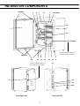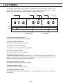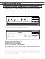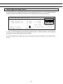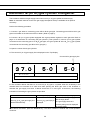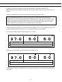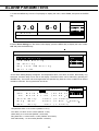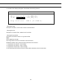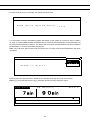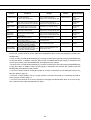
1
INSTRUCTION MANUAL
Multi Gas Incubator
MCO-19M UVH
MCO-19M UV
MCO-19M
CONTENTS
INTRODUCTION
PRECAUTIONS FOR SAFE OPERATION
LABELS ON THE INCUBATOR
ENVIRONMENTAL CONDITIONS
INCUBATOR COMPONENTS
Control panel and keypad
Remote alarm terminals
INSTALLATION SITE
INSTALLATION
Connection of CO2 gas cylinder
Connection of N2 (or O2) gas cylinder
Connection of gas injection nozzle
Using the inner door and gastight split doors
PREVENTING CONTAMINATION
PRECAUTIONS FOR CULTURES
Using the unlock key
CORRECT OPERATION
LCD PANEL
BASIC OPERATIONS ON CONTROL PANEL
BASIC PARAMETERS
Setting the chamber temperature, CO2 and CO2 density
Setting the key lock
Releasing the key lock
Setting the key lock password
Automatic N2 (or O2) gas cylinder changeover
Setting the upper limit alarm temperature
ALARM PARAMETERS
UV LAMP PARAMETERS
Using the UV lamp
Precautions when using the UV lamp
Setting the UV lamp ON period
Lighting the UV lamp for 24 hours
OTHER PARAMETERS
Setting the date, time, and log interval
Initial settings (LCD/DAQ parameters)
DISPLAYING THE LOG
Transferring data
WATER LEVEL SENSOR
ROUTINE MAINTENANCE
Cleaning the chamber and inner attachments
Filling the humidifying pan
H2O2 DECONTAMINATION
H2O2 decontamination
Precautions when handling H2O2 decontamination reagent
ALARMS, SAFETY, AND SELF-DIAGNOSIS
CALIBRATION
Temperature/CO2/O2 calibration
TROUBLESHOOTING
DISPOSING OF THE MULTI-GAS INCUBATOR
AUTOMATIC CO2 CYLINDER CHANGEOVER
AUTOMATIC CO2 AND O2 DENSITY CALIBRATION
STACKING INCUBATORS
1
P. 3
P. 4
P. 8
P. 8
P. 9
P. 12
P. 13
P. 14
P. 15
P. 16
P. 17
P. 18
P. 18
P. 19
P. 20
P. 21
P. 21
P. 22
P. 24
P. 25
P. 26
P. 27
P. 28
P. 30
P. 32
P. 33
P. 34
P. 34
P. 35
P. 36
P. 37
P. 38
P. 40
P. 41
P. 43
P. 44
P. 45
P. 48
P. 49
P. 51
P. 54
P. 55
P. 58
P. 60
P. 62
P. 67
P. 69
P. 72
CONTENTS
SPECIFICATIONS
PERFORMANCE
SAFETY CHECK SHEET
P. 74
P. 75
P. 76
2
INTRODUCTION
■ Read this manual carefully before using the Product and follow the instructions for safety operation.
■ Sanyo disavows any responsibility for safety if the Product is used for other than the intended use or
used with any procedures other than those given in this manual.
■ Keep this manual in a suitable place so that it can be referred to as necessary.
■ The contents of this manual are subject to change without notice for improvement of performance or
functions.
■ Contact a Sanyo sales representative or agent if any page of the manual is lost or the page order is
incorrect.
■ Contact a Sanyo sales representative or agent if any point in this manual is unclear or if there are any
inaccuracies.
■ No part of this manual may be reproduced in any form without the expressed written permission of
Sanyo.
CAUTION
SANYO guarantees the product under certain warranty conditions.
responsible for any loss of content or damage of content.
3
SANYO in no way shall be
PRECAUTIONS FOR SAFE OPERATION
It is imperative that the user complies with this manual as it contains
important safety advice.
Items and procedures are described so that you can use this unit correctly and safely.
If the precautions advised are followed, this will prevent possible injury to the user and
any other person.
Precautions are illustrated in the following way:
WARNING
Failure to observe WARNING signs could result in a hazard to personnel
possibly resulting in serious injury or death.
CAUTION
Failure to observe CAUTION signs could result in injury to personnel and
damage to the unit and associated property.
Symbol shows;
this symbol means caution.
this symbol means an action is prohibited.
this symbol means an instruction must be followed.
Be sure to keep this manual in a place accessible to users of this unit.
< Label on the unit >
This mark is labeled on the cover in which the electrical components of high voltage
are enclosed to prevent the electric shock.
The cover should be removed by a qualified engineer or a service personnel only.
WARNING
As with any equipment that uses CO2 gas, there is a likelihood of oxygen depletion in the vicinity
of the equipment. It is important that you assess the work site to ensure there is suitable and
sufficient ventilation. If restricted ventilation is suspected, then other methods of ensuring a
safe environment must be considered. These may include atmosphere monitoring and
warning devices.
4
WARNING
Do not use the unit outdoors. Current leakage or electric shock may result if the unit is exposed to
rain water.
Only qualified engineers or service personnel should install the unit.
unqualified personnel may cause electric shock or fire.
The installation by
Install the unit on a sturdy floor and take an adequate precaution to prevent the unit from
turning over. If the floor is not strong enough or the installation site is not adequate, this may result
in injury from the unit falling or tipping over.
Never install the unit in a humid place or a place where it is likely to be splashed by water.
Deterioration of the insulation may result which could cause current leakage or electric shock.
Never install the unit in a flammable or volatile location. This may cause explosion or fire.
Never install the unit where acid or corrosive gases are present as current leakage or electric
shock may result due to corrosion.
Always ground (earth) the unit to prevent electric shock. If the power supply outlet is not
grounded, it will be necessary to install a ground by qualified engineers.
Never ground the unit through a gas pipe, water main, telephone line or lightning rod. Such
grounding may cause electric shock in the case of an incomplete circuit.
Connect the unit to a power source as indicated on the rating label attached to the unit. Use
of any other voltage or frequency other than that on the rating label may cause fire or electric shock.
Never store volatile or flammable substances in this unit if the container cannot be sealed. These
may cause explosion or fire.
Do not insert metal objects such as a pin or a wire into any vent, gap or any outlet on the unit.
This may cause electric shock or injury by accidental contact with moving parts.
Use this unit in safe area when treating the poison, harmful or radiate articles. Improper use
may cause bad effect on your health or environment.
Turn off the power switch (if provided) and disconnect the power supply to the unit prior to any
repair or maintenance of the unit in order to prevent electric shock or injury.
Do not touch any electrical parts (such as power supply plug) or operate switches with a wet
hand. This may cause electric shock.
5
WARNING
Ensure you do not inhale or consume medication or aerosols from around the unit at the time of
maintenance. These may be harmful to your health.
Never splash water directly onto the unit as this may cause electric shock or short circuit.
Never put containers with liquid on the unit as this may cause electric shock or short circuit when
the liquid is spilled.
Never bind, process, or step on the power supply cord, or never damage or break the power
supply plug. A broken supply cord or plug may cause fire or electric shock.
Do not use the supply cord if its plug is loose. Such supply cord may cause fire or electric shock.
Never disassemble, repair, or modify the unit yourself. Any such work carried out by an
unauthorized person may result in fire, or electric shock or injury due to a malfunction.
Disconnect the power supply plug if there is something wrong with the unit.
abnormal operation may cause electric shock or fire.
Continued
When removing the plug from the power supply outlet, grip the power supply plug, not the cord.
Pulling the cord may result in electric shock or fire by short circuit.
Disconnect the power supply plug before moving the unit. Take care not to damage the power
cord. A damaged cord may cause electric shock or fire.
Disconnect the power plug when the unit is not used for long periods. Keeping the connection
may cause electric shock, current leakage, or fire due to the deterioration of insulation.
If the unit is to be stored unused in an unsupervised area for an extended period, ensure that
children do not have access and that doors cannot be closed completely.
The disposal of the unit should be accomplished by appropriate personnel. Remove doors to
prevent accidents such as suffocation.
Do not put the packing plastic bag within reach of children as suffocation may result.
Use the reagent specified by Sanyo for H2O2 decontamination. Using a different H2O2 solution
may result in explosion or damage to the Incubator.
When performing H2O2 decontamination, securely close gastight split doors, inner door and outer
door. Failure to do so may be harmful to health due to leakage of H2O2 gas.
During H2O2 decontamination, plug the access hole with the silicon cap that is provided. Failure
to do so may be harmful to health due to leakage of H2O2 gas.
6
CAUTION
Use a dedicated power source (a dedicated circuit with a breaker) as indicated on the rating label
attached to the unit. A branched circuit may cause fire resulting from abnormal heating.
Connect the power supply plug to the power source firmly after removing the dust on the plug.
A dusty plug or improper insertion may cause a heat or ignition.
Never store corrosive substances such as acid or alkali in this unit if the container cannot be
sealed. These may cause corrosion of inner components or electric parts.
Check the setting when starting up of operation after power failure or turning off of power
switch. The stored items may be damaged due to the change of setting.
Be careful not to tip over the unit during movement to prevent damage or injury.
Prepare a safety check sheet when you request any repair or maintenance for the safety of service
personnel.
Wear rubber gloves when handling the H2O2 reagent. Direct contact with the H2O2 reagent may
result in inflammation of the skin.
H2O2 decontamination can be performed only for the chamber and chamber attachments with
standard specifications, and not for any other objects.
Perform H2O2 decontamination with the chamber attachments arranged as specified by Sanyo.
Arranging them in a different way may result in insufficient decontamination.
After H2O2 decontamination has been completed, wear rubber gloves and use a non-woven cloth
to wipe off the residual H2O2 fluid from the bottom of the chamber, any objects that were
decontaminated, and the bottoms of ducts.
7
LABELS ON THE INCUBATOR
Warning and caution labels are attached to the Incubator. The following table describes the labels.
This label is attached to covers that access high-voltage electrical components to
prevent electric shock. Only a qualified engineer or service personnel should be
allowed to open these covers.
This symbol indicates an ultraviolet light (UV) caution.
This symbol indicates that caution is required. Refer to product documentation for
details.
This symbol indicates a hot surface.
This symbol indicates an earth.
This symbol means “ON” for a power switch.
This symbol means “OFF” for a power switch.
ENVIRONMENTAL CONDITIONS
This equipment is designed to be safe at least under the following conditions (based on the IEC 61010-1):
■ Indoor use;
■ Altitude up to 2000 m;
■ Ambient temperature 5oC to 40oC
■ Maximum relative humidity 80% for temperature up to 31oC decreasing linearly to 50% relative humidity
at 40oC;
■ Mains supply voltage fluctuations not to exceed
10% of the nominal voltage;
■ Other supply voltage fluctuations as stated by the manufacturer;
■ Transient overvoltages according to Installation Categories (Overvoltage Categories) II; For mains
supply the minimum and normal category is II;
■ Pollution degree 2 in accordance with IEC 60664.
8
INCUBATOR COMPONENTS
Handles
6
3
2
9
13
10(inside)
5
7
1
8
16, 17(inside)
For MCO-19M(UVH)/19M(UV) or
when MCO-19UVS is installed.
Handles
24
12
11
15
For MCO-19M(UVH)/19M(UV) or
when MCO-19UVS is installed.
14
25
4
19
21
22
18
23
20
Rear Right Side
Rear Left Side
9
1. Outer door: The outer door is held to the frame with a magnetic seal. A door heater is installed in the
door panel. The door opening is reversible. Contact a Sanyo representative or agent to change the door
hinge from left to right or vice versa.
2. Inner door: Open when take the trays out or clean inside.
3. Gastight split door: Made of tempered glass, however avoid excessive impact on the glass.
4. Leveling feet: The leveling feet can be turned to adjust the height. Adjust the feet so that the Incubator
is level.
5. Trays: Set trays at the same level as each gastight split door. Open a inner door when take the
tray out.
6. Tray supports: The tray supports can be removed by lifting the front side and pulling toward you.
7. Side supports: The right and left side supports can be removed for disinfection. Refer to page 45.
8. Duct: The duct for the path for circulating air. It is removable.
9. Fan cover: The fan cover serves as the inlet for circulating air. It is removable.
10. Fan (inside the duct): The fan is made from polypropylene resin. It can be disinfected in an
autoclave.
11. Sample air outlet: The sample air outlet also functions as an internal gas outlet. Normally, cover this
outlet with the sample air outlet cap.
12. Sample air outlet cap: Always attach this cap except when using the sample air outlet.
13. Door switch: Detects the door opening/closing and stops the circulating fan and electromagnetic
valve for CO2 and N2/O2 when door is open. UV lamp is also deactivated by door opening*.
14. Humidifying pan: Fill the humidifying pan with sterile distilled water. Install the pan properly so that it
can be covered with the pan cover.
15. Humidifying pan cover: The cover prevents UV light entering the chamber. When filling the pan, lift
the front side and take out the pan. Refer to page 48 for details.
16. UV lamp*: This Sanyo UV lamp does not generate ozone. Never look directly at the UV light. For
replacement, contact a Sanyo representative or agent.
17. Water level sensor for humidifying pan: This sensor detects the water level in the humidifying pan.
Refer to page 44 for details.
18. Remote alarm terminals: Refer to page 13.
19. Access port: Place the silicon caps on the port both outside and inside when the port is not being
used.
20. Power switch: This is the main switch for the Incubator. It also functions as an overcurrent breaker.
21. Glow starter*: The glow started if for the UV lamp (model FG-7P)
22. Connecting port A/B for CO2 gas pipe: When the optional MCO-21GC Automatic CO2 Cylinder
Changeover System is installed, both ports A and B are available. If the MCO-21GC is not installed, only
port A is available. Refer to page 16 for gas cylinder connection. Ensure that the gas pressure is set at
0.03 MPaG (0.3 kgf/cm2G, 4.3 psiG). Refer to page 67 for automatic CO2 cylinder changeover.
10
23. Connecting port A/B for N2/O2 gas pipe: Refer to page 17 for gas cylinder connection. Ensure that
the gas pressure is set at 0.05 MPaG (0.5 kgf/cm2G, 7.1 psiG). Refer to page 30 for automatic N2 (or O2)
gas cylinder changeover.
24. Attachment location for electric key: This is the attachment location for the electric key included in
the optional Component H2O2 Decontamination Kit (MCO-HL). This kit must be attached to perform H2O2
decontamination. Refer to the installation procedure for MCO-HL for details.
25. Gas injection nozzle
* MCO-19M(UVH)/19M(UV) or when an optional UV System Kit (MCO-19UVS) is installed.*
11
Control panel and keypad
LCD panel
2
10
1
3
4
7
9
8
5
6
1. Upper limit regulator:
This regulator is used to set the upper
temperature limit.
6. CE Key:
Press this key to clear the entered value
when entering a setting.
2. OVERHEAT indicator:
This indicator lights when the chamber
temperature reaches the upper limit.
7. Cursor Keys (Up, Down, Left, and Right):
Use these keys to move the cursor on the
LCD panel.
3. MENU Key:
Press this key to access the menu.
8. ENTER Key:
Press this key to select a menu command.
When entering a setting, pressing this key to
move to the next parameter.
4. Contrast knob:
Turn this knob to adjust the contrast of the
LCD.
9. Numeric Keys
5. BUZZER Key:
Press this key to silence the buzzer.
Note: It is not possible to silence the
buzzer for an upper limit temperature
alarm.
10. H2O2 Key:
Press this key to start H2O2 decontamination.
Refer to page 49 for details.
The following optional components must be installed to perform decontamination.
UV Lamp Add-on Kit (MCO-19UVS) (This is provided as standard equipment for the MCO-19M(UV).)
H2O2 Decontamination Kit (MCO-HL)
H2O2 Generator (MCO-HP)
12
Remote alarm terminal
The remote alarm terminal is located at the rear right side of the incubator.
Remote alarm
terminal
The alarm is outputted from this terminal. Contact capacity is DC 30 V, 2 A.
Contact output:
between COM. and N.O.
between COM. and N.C.
At normal
Open
Close
At abnormal
Close
Open
Note:
The alarm is actuated when the power cord is disconnected from the outlet or the power switch is OFF.
• The remote alarm cannot be stopped by pressing the alarm buzzer stop key (BUZZER) since the remote
alarm is not conjunct with the alarm buzzer stop key (BUZZER).
Remote alarm terminal
13
INSTALLATION SITE
For correct operation of the Incubator, install it in a location with the following conditions.
WARNING
When using CO2 gas for control, make sure that there is adequate ventilation. Using CO2 gas in a
small room without adequate ventilation may cause gas poisoning or oxygen deprivation. In addition,
when opening the Incubator doors, do not directly inhale the air in the chamber.
Si l’appareil est utilisé dans un evdroit restreint, le niveau de la densite CO2 de l’air peut s’élever et peut
être nocif aux humains. Evitez d’aspirer l’air provenant de l’inérieur de l’appareil quand vous ouverz la
porte.
z Normal air environment
Install the Incubator in an environment with normal air.
z Do not expose to direct sunlight
Do not install the Incubator in a location where it will be exposed to direct sunlight. If the Incubator is
operated in direct sunlight, performance will be adversely affected.
z Separate from heat sources
Do not install the Incubator near significant heat sources, such as heaters, boilers, ovens, or autoclaves.
Heat will adversely affect the performance of the Incubator.
z Ambient temperature at least 5°C lower than set temperature
The control temperature of the Incubator is at least 5°C higher than the ambient temperature. For
example, if the chamber is controlled at 37°C, the ambient temperature must normally be no more than
32°C. Do not allow the ambient temperature to become too high.
z Strong and level floor
Select a site with a strong and level floor. If the floor is uneven or the installation is not level, the Incubator
will be unstable and this may cause accident or injury. To avoid vibration and noise, always make sure
that the installation is stable. An unstable surface may result in vibration or noise.
WARNING
Install the Incubator at a location that can support the weight. If the floor is not strong enough or if the
installation is insufficient, the Incubator may fall over and cause injury.
Always make sure that the floor is strong, even, and level, and that the Incubator will not tip over.
An insufficient installation may result in injury due to water leakage or the Incubator falling over.
z Low humidity
Select a site with a relative humidity of 80% or lower. Using the Incubator in high humidity may result in
current leakage or electric shock.
WARNING
Do not use the Incubator outdoors. If the Incubator is exposed to rain water, it may result in current
leakage or electric shock.
Never install the Incubator in a moist location, such as near a sink or water line, or where it is
likely to be exposed to water. In addition, do not install it near water or steam pipes. Moisture can
cause the insulation to deteriorate, which may result in current leakage or electric shock.
z No inflammable or corrosive gas
Never install the Incubator in a location where it will be exposed to inflammable or corrosive gas. Doing
so may result in explosion or fire. In addition, insulation may deteriorate due to corrosion of protective
casing, resulting in current leakage or electric shock.
z No falling objects
Do not install the Incubator in a location where there is the possibility of objects falling from above. Doing
so may result in damage or accident.
14
INSTALLATION
1. Remove the packing tape and clean up.
Remove all the tape that is securing the doors and inner attachments. Open the doors for ventilation. If
the outer panels are dirty, dampen a cloth with a diluted neutral detergent and wipe them. (Using an
undiluted solution may damage the plastic. Follow the diluting instructions for the detergent that is used.)
Wipe off the residual detergent with a wet cloth and then wipe off any moisture.
WARNING
Do not leave plastic wrapping bags within reach of children. If a bag is placed over a child’s head, it
can block the mouth and nose and cause suffocation.
2. Adjust the leveling feet.
Adjust the leveling feet by turning them counterclockwise to level the Incubator. (See the illustration on
the right.)
3. Ground the Incubator.
Ground the Incubator during installation to prevent electric shock in case the insulation is not sufficient. If
there is no ground wire at the location, consult with qualified service personnel.
z When a ground must be installed
If a grounded 3-pole outlet is not available, then a ground must be installed. Consult with qualified service
personnel.
WARNING
To prevent electric shock, always ground the Incubator. If grounding is not possible, then have a ground
installed by qualified personnel. If the Incubator is not grounded, it may result in electric shock.
Never connect the ground wire to a gas pipe, water pipe, lightning rod, or telephone ground wire.
Doing so may cause electric shock.
z Installing a ground fault circuit breaker
If using the Incubator in a location with moisture or humidity cannot be avoided, then it is recommended
that a ground fault circuit breaker be installed in the power supply circuit (i.e., the power supply at the
Incubator). Have the circuit breaker installed by qualified service personnel.
CAUTION
Do not climb on the Incubator or place objects on top of it. Doing so may damage it or cause it to fall
over, resulting in injury. If it is to be stacked, refer to page 72 and stack it securely.
z When the Incubator is not in use
Empty the water from the humidifying pan and remove moisture from the chamber. Make sure that the
chamber is completely dry before closing the doors. Failure to do so may result in damage.
z Before moving the Incubator
Before moving the Incubator, empty the water from the humidifying pan, disconnect the power supply plug
from the outlet, and make sure that the cord will not be damaged. Failure to do so may result in electric
shock or fire.
15
Connection of CO2 gas cylinder
WARNING
When connecting a gas cylinder to the Incubator, confirm the gas type. Confirm that the connections
are secure and that no gas will escape. Be sure to use the specified pressure. Using an incorrect
gas or pressure may result in explosion or fire, or in gas poisoning or oxygen deprivation due to escaping
gas.
Install the Incubator in a location with adequate ventilation. If adequate ventilation cannot be
provided, then install an alarm system using CO2 and O2 densitometers.
1. Use a liquefied CO2 gas cylinder (at least 99.5% pure). The siphon (dip tube) type cannot be used.
2. Install the Gas Pressure Regulator (MCO-100L, purchased separately) specified by Sanyo on the CO2
gas cylinder. Otherwise, use a CO2 gas pressure regulator rated at 25 MPaG (250 kgf/cm2G, 3600 psiG)
for the primary pressure, and 0.2 MPaG (2 kgf/cm2G, 30 psiG) for the secondary pressure.
3. Using the gas supply pipe that is provided, connect the CO2 gas pressure regulator to the CO2 gas pipe
inlet (located at the lower left-hand side on the rear panel of the Incubator).
Note:
If CO2 is supplied to multiple CO2 Incubators from a single gas cylinder, a CO2 solid will be formed in the
gas pressure regulator. The gas pressure regulator safety valve will operate, and there may an explosive
sound.
When the MCO-21GC is not mounted
Using the gas supply pipe that is provided, connect the CO2 gas pressure regulator for the CO2 gas
cylinder to CO2 gas pipe connection port A on the Incubator. After connecting the pipe, check to make
sure that no gas is leaking.
When the MCO-21GC is mounted
Connect a pair of CO2 gas cylinders with CO2 gas pressure regulators independently. The gas supply line
will be switched automatically. Connect the main cylinder to port A and the reserve cylinder to port B. After
connecting the cylinders, check to make sure that no gas is leaking.
z For details on installing the optional automatic CO2 Cylinder Changeover System (MCO-21GC), refer to
the MCO-21GC installation guide. For details on using the MCO-21GC, refer to page 67.
4. Set the CO2 gas on the secondary side to 0.03 MPaG (0.3 kgf/cm2G, 4.3 psiG) for gas injection. As the
pressure increases, the CO2 gas concentration control range will increase. Excessive pressure may
cause gas supply lines inside the Incubator to come loose, which may result in gas poisoning or oxygen
deprivation due to the escaping of gas. If gas lines come loose, the Incubator must be repaired.
z The gas lines connected to the Incubator will degrade over time. If any deterioration or abnormalities
are found during inspection, replace the lines immediately.
16
Connection of N2 (or O2 ) gas cylinder
WARNING
Check the gas type and ensure that it is fit for the purpose. Make sure that all pipes are
connected correctly and are not liable to become disconnected. Ensure that the gas pressure is
set at the specified value. Improper connection of the gas pipe or use of incorrect gas pressure
may result in leakage of gas. Elevated level of gas can be hazardous to health and may lead to
asphyxiation and risk of death.
This incubator needs N2 or O2 gas depending on the setting of O2 density. The selection is as follows:
When the setting of O2 density is less than 18%: N2 gas
When the setting of O2 density is more than 22%: O2 gas
O2 density in the atmosphere is about 20%. For the control of O2 density in the chamber, O2 gas is
diluted by N2 gas when the setting of O2 density is less than that of the atmosphere. On the contrary, O2
gas is added when the setting of O2 density is more than that of the atmosphere.
1. Install a gas pressure regulator (optional accessory MCO-100L) on N2 or O2 gas cylinder. Or use a
regulator rated at 25 MPaG (250 kgf/cm2G, 3600 psiG) on the primary side and 0.2 MPaG (2.0 kgf/cm2G,
30 psiG) on the secondary side.
2. Using the gas tube provided, connect the pressure regulator to the connecting port A/B for N2/O2 gas
pipe located at the rear left side of the incubator. Connect the main cylinder to the connecting port A for
N2/O2 gas pipe and connect the sub-cylinder to the connecting port B for N2/O2 gas pipe so that the gas
supply can be switched automatically when one gas cylinder is empty. Connect the same gas type to
both connecting port A/B for N2/O2 gas pipe. Never connect N2 gas and O2 gas at the same time to the
connecting port A/B for N2/O2 gas pipe respectively.
3. Set the N2 or O2 gas pressure on the secondary side to 0.05 MPaG (0.5 kgf/cm2G, 7.1 psiG) (at gas
injection). The higher gas pressure makes control range of O2 density wider. In addition, excessive
pressure may cause disconnection of internal pipes inside the incubator, which will result in leakage of N2
or O2 gas into the atmosphere. Elevated level of CO2 gas or O2 gas can be hazardous to health and
may lead to asphyxiation and risk of death or fire by gas leakage. The repair of the incubator will be
necessary if the internal pipe is disconnected.
4. Check that no gas is leaking at any point where the pipe connects with the gas regulator or the
incubator.
z The gas lines connected to the Incubator will degrade over time. If any deterioration or abnormalities
are found during inspection, replace the lines immediately.
WARNING
O2 gas increases the susceptibility of substances to burn. Take care of the handling of flame in a room
where the incubator is installed.
17
Connection of gas injection nozzle
In the case of control of O2 density in the chamber, connect the gas injection nozzle to the gas injection
port by using the connecting pipe enclosed (inner diameter; 5 mm, outer diameter; 9 mm, length; 400
mm). This helps faster recovery of humidity after opening of the inner door.
Fill the humidifying pan with sterile distilled water so that the injection nozzle can be under the water level.
Using the inner door and gastight split doors
zTo effectively use gastight split doors, set three trays (standard equipment) at the same level as bottom
side of each gastight split door.
At the same level
as bottom side of
each gastight
split doors
18
PREVENTING CONTAMINATION
To prevent contamination of the chamber, select a suitable installation site.
z Avoid locations with high temperatures or humidity.
Avoid locations with high temperatures or humidity, because of a greater presence of microorganisms in
the air.
z Avoid locations with passers-by or drafts.
Avoid locations near doors, air conditioners, fans, etc., where passers-by or drafts can facilitate the entry
of microorganisms into the chamber.
z If possible, use a cleanroom.
To achieve a better culture, it is recommended that a cleanroom be used if one is available.
z Use clean containers.
The greatest cause of contamination is dirty containers for cultures. Be careful not to get containers or
trays dirty when taking them in and out.
z Keep the chamber clean.
Wipe off any fingerprints. If water spills from the humidifying pan, or if the doors are left open for a long
time, condensation may form on the inside of the doors. If that occurs, wipe off the condensation with a
dry sterile gauze. In particular, clean and disinfect the chamber if the culture medium is spilled. For details,
refer to Routine Maintenance on page 45.
z Use sterile distilled water in the humidifying pan.
Always use sterile distilled water in the humidifying pan. Do not use ultrapure water, because it may
contain red rust-like suspended particles.
A water level alarm is displayed in the status display area on the control panel. Quickly refill the water in
the pan when the water level alarm is displayed. Adding low-temperature water will significantly lower the
temperature in the chamber. Clean the humidifying pan once a month.
z Keep the Incubator out of direct airflows from air conditioners or fans.
Cool airflow from an air conditioner may cause condensation and lead to possible contamination.
19
PRECAUTIONS FOR CULTURES
z Leave space between culture containers.
Always leave space for ventilation between culture containers (Petri dishes, flasks, etc.). Inadequate
spacing may result in uneven temperature distribution and CO2 gas concentration.
z Do not place harmful materials in the chamber.
Never place samples that release acidic, alkali, or corrosive gas in the chamber. Doing so may cause
damage resulting from discoloration or corrosion.
z Close the inner door and all gastight split doors.
Always close the inner door and all gastight split doors before closing the outer door. Failure to close the
inner door or any gastight split door will adversely affect performance even if the outer door is closed.
z Open and close the doors gently.
Always open and close the doors gently. Closing the doors forcefully may cause spillage of the culture
medium, incomplete closing, or damage to the gasket. Before opening the inner door, check through the
glass to confirm that the UV lamp is OFF (if the MCO-19M(UVH)/19M(UV) or the optional MCO-19UVS is
installed).
z Be careful when closing the outer door.
Use the handle when closing the outer door. Holding the door in other places may cause injury by getting
fingers caught in the door. Do not lean on the outer door. Doing so may result in injury from the outer door
coming loose or the Incubator falling over, or it may cause current leakage or electric shock.
z Be careful of the inside of the outer door.
The inside of the outer door may become hot.
z Avoid using excessive force on the inner door.
Do not put your hand on the glass, poke it with sharp objects, or apply strong force. Doing so may result
in injury from breaking the glass.
z Check the cause of any alarm buzzer.
If an alarm buzzer sounds while the Incubator is in use, immediately check the cause of the alarm. For
details on what may cause an alarm buzzer to sound, refer to page 55.
20
Using the Unlock Key
z Unlocking when power is interrupted
If power is interrupted to the MCO-19M(UVH)/19M(UV) with an MCO-HL installed, the outer door is
electrically locked. To unlock the outer door while the power is interrupted, use the unlock key that is
provided. To lock the outer door again, turn the unlock key to the lock direction while the door is open.
After the door has been locked condition manually, then close the door.
Note:
The outer door cannot be locked by using the unlock key while the door is closed. Lock the door while it is
open. Attempting to turn the unlock key while the door is closed may damage the electric lock system.
WARNING
For the MCO-19M(UVH)/19M(UV) with an MCO-HL installed, the outer door is electrically locked during
decontamination. The chamber is filled with H2O2 gas during decontamination. Do not unlock the door
during decontamination.
CORRECT OPERATION
Use the following procedure to start trial operation or actual operation of the Incubator.
1. Install the Incubator correctly, referring to Installation on page 15.
2. Remove the packing materials from the chamber and inner attachments. Clean and disinfect the
chamber and inner attachments, referring to Routine Maintenance on page 45.
3. Add approximately 1.5 L of sterile distilled water to the humidifying pan. (Refer to page 48.)
4. Turn ON the power supply switch on the left side of the rear panel of the Incubator.
Note:
The humidity in the Incubator chamber is adjusted to the optimum setting. To prevent condensation on
the surface inside chamber and the inner door, there is a low-temperature area under the humidifying pan
in the bottom of chamber to recondense evaporated moisture. Condensation may occur around the
humidifying pan at the bottom of the chamber, but this does not indicate a problem.
21
LCD PANEL
The following display (called the Top Display) will appear when the power switch is turned ON. The
default temperature is 37.0oC, the default CO2 density is 0% and the default O2 density is 20%. The date
and time are preset at the factory. Refer to page 38 to change the date and time.
1
3
0 0
1 2
1 T e mp
1
1
3 7 . 0
2
2
o
1
2
1
3
C
1 1
4 5
1
6
5
1
7
1 1
8 9
CO2
2
0
4
9 5
S t a t u s
10 6
OK
2 2
2 3
5 . 0%
6
2
4
A
2 2
5 6
2
7
B
U V
R H
2
8
8
2 3
9 0
O2
3
1
3
2
3 3
3 4
3
5
3 3
6 7
5 . 0%
3
8
A
P A N
D o o r : O p e n
7
4
7
1. Display of set value of temperature
The set value of chamber temperature is displayed.
2. Display of current temperature
The current chamber temperature is displayed.
3. Display of set value of CO2 density
The set value of the chamber CO2 density is displayed.
4. Display of current CO2 density
The current chamber CO2 density is displayed.
5. Display of current CO2 cylinder
A and B will be displayed if the optional Automatic CO2 Cylinder Changeover System (MCO-21GC) is
installed. The port of the CO2 gas pipe that is currently supplying CO2 will be displayed in reverse video.
Nothing will be displayed if the MCO-21GC is not installed.
6. Display of set value of O2 density
The set value of the chamber O2 density is displayed.
7. Display of current O2 density
The current chamber O2 density is displayed.
8. Display of current N2/O2 cylinder
The connecting port A/B for N2/O2 gas pipe that is currently supplying N2 or CO2 will be displayed in
reverse video.
22
3 4
9 0
B
. .
.
.
3
2
1
9. Status display field
Various status or alarms are displayed.
When UV lamp is lit: “UV” is displayed in reverse video. (If the MCO-19M(UVH)/19M(UV) or the optional
MCO-19UVS is installed).
When humidifying water is low: “RH PAN” is displayed in reverse video and blinks.
When the door is open: Door: Open” is displayed in reverse video.
10. Message display field
A message is displayed when fault occurs. The message is displayed alternately in normal characters
and reverse video. Refer to pages from 55 to 57 for alarm details. OK is displayed during normal
operation.
23
BASIC OPERATIONS ON CONTROL PANEL
The following operation are possible through control panel:
z Setting the temperature
The chamber temperature can be set (page 25).
z Setting the CO2 density
The chamber CO2 density can be set (page 25).
z Setting the O2 density
z Setting the key lock
The chamber O2 density can be set (page 25).
Changing the temperature and CO2 density can be disabled (page 26).
z Setting alarms The temperature alarm, CO2 density alarm, O2 density alarm (page 33) and upper
limit alarm temperature (page 32) can be set.
z Setting UV parameters ON/OFF parameters and the ON period of the UV lamp can be set for the
MCO-19M(UVH)/19M(UV) or when the Incubator is equipped with the optional MCO-19UVS (page 36).
z Setting other parameters The initial settings of the date, time, and log cycle (page 38), and the
LCD display and baud rate (page 40) can be set.
z Displaying the operation log and transferring data
A graph of past operation data can be
displayed (page 41) and operation data can be transferred to a PC (page 43).
z H2O2 decontamination H2O2 decontamination of the chamber and internal attachments can be
performed when the optional H2O2 Generator (MCO-HP) is installed (page 49).
z Automatic N2 (or O2) gas cylinder changeover The N2 (or O2) gas cylinder can be switched (page
30). The CO2 gas cylinder can be switched when the optional automatic CO2 Cylinder Changeover
System (MCO-21GC) is installed (page 67).
z Setting the standard gas density
The standard gas density can be set when the optional
Automatic Standard Gas Calibration Kit (MCO-SG) is installed. (page 69)
24
BASIC PARAMETERS
Setting the chamber temperature, CO2 and O2 density
The setting procedure for the chamber temperature, CO2 and O2 density are given below. (Default
settings: Chamber temperature: 37oC, CO2 density: 0%, O2 density: 20%)
The Incubator automatically starts operation using these settings after the power is turned ON.
1. From the Top Display, press the MENU Key to access the menu. Select Set and press the ENTER
Key.
1 T e mp
3 7 . 0
2
o
C
C O 2
5 . 0 %
4
5
S t a t u s
6
O K
5 . 0 %
M E N U
. .
.
.
3
O 2
S e t
L o g
T o o l s
7
2. The Stand-By Setting Display will be displayed. Set the parameters.
1
S t a n d - b y
S e t t i n g
2
T e mp e r a t u r e
3
C O 2
D e n s i t y
4
O 2
D e n s i t y
(
0 . 0
0 . 0 %
(
0 . 0 %
-
2 0 . 0 %
(
1 . 0 %
-
M E N U
5 0 . 0 o C )
O K
2 0 . 0 %)
C a n c e l
1 8 . 0 %)
( 2 2 . 0 %
-
8 0 . 0 %)
3 7 . 0
o
C
5
K e y
6
H i g h
L o c k
L i mi t
0
5 2 . 0
o
C
-
( 0 . U n l o c k
o
1 . L o c k )
C
The setting ranges of the parameters are as follows:
●Temperature: 0 to 50oC. To 37.0oC, enter 370.
●CO2 density: 0 to 20%. To set 5.0%, enter 050.
●O2 density: 1 to 18 and 22 to 80%. To set 5.0%, enter 050.
3. Press the MENU Key to display the menu after setting the parameters. Select OK and press the
ENTER Key. The settings will be saved.
Note:
When starting the Incubator for the first time or after not using it for an extended period of time, allow at
least 4 hours for the chamber temperature, humidity, CO2 sensor and O2 sensor to become stable after
setting the desired chamber temperature at a 0% CO2 density and a 20% O2 density. Then change the
setting to the desired CO2 and O2 density.
25
Setting the key lock
1. To set the key lock, change the value of the key lock parameter from 0 to 1 on the Stand-by Setting
Display and press the ENTER Key. The buzzer will sound briefly and the keys will be locked.
1
S t a n d - b y
S e t t i n g
2
T e mp e r a t u r e
3
C O 2
D e n s i t y
4
O 2
D e n s i t y
(
0 . 0
5 . 0 %
(
0 . 0 %
-
5 . 0 %
(
1 . 0 %
-
M E N U
5 0 . 0 o C )
O K
2 0 . 0 %)
C a n c e l
1 8 . 0 %)
( 2 2 . 0 %
-
8 0 . 0 %)
3 7 . 0
o
C
5
K e y
6
H i g h
L o c k
L i mi t
1
5 2 . 0
o
C
-
( 0 . U n l o c k
o
1 . L o c k )
C
2. “Key Lock” will be displayed in reverse video at the right side of “Stand-by Setting”, and changing the
temperature and CO2 density settings will be disabled.
3. Press the MENU Key to display the menu, select OK and press the ENTER Key. The settings will be
saved.
26
Releasing the key lock
1. To remove the key lock, change the value of the key lock parameter from 1 to 0 on the Stand-by
Setting Display and press the ENTER Key.
1
S t a n d - b y
S e t t i n g
2
T e mp e r a t u r e
3
C O 2
D e n s i t y
4
O 2
D e n s i t y
K e y
3 7 . 0
o
C
(
0 . 0
5 . 0 %
(
5 . 0 %
(
5
K e y
6
H i g h
L o c k
0
L i mi t
L o c k
5 2 . 0
o
C
5 0 . 0
0 . 0 %
-
2 0 . 0 %)
1 . 0 %
-
1 8 . 0 %)
( 2 2 . 0 %
-
8 0 . 0 %)
( 0 . U n l o c k
o
o
-
C )
1 . L o c k )
C
2. The cursor will move to the Password Field. Input the 4-digit password (default: 0000) and press the
ENTER Key. When key lock is released, the buzzer will sound briefly, and “Key Lock” will disappear from
the Stand-by Setting Display.
1
S t a n d - b y
2
T e mp e r a t u r e
3
C O 2
D e n s i t y
4
O 2
D e n s i t y
K e y
S e t t i n g
o
(
0 . 0
5 . 0 %
(
5 . 0 %
(
3 7 . 0
C
5
K e y
6
H i g h
L o c k
L i mi t
L o c k
C
o
-
5 0 . 0
C )
0 . 0 %
-
2 0 . 0 %)
1 . 0 %
-
1 8 . 0 %)
( 2 2 . 0 %
-
8 0 . 0 %)
P a s s w o r d
0
5 2 . 0
o
o
C
3. Press the MENU Key to display the menu, select OK and press the ENTER Key. The settings will be
saved.
Note: The buzzer will sound for a long time if the wrong password is entered. Enter the correct password.
The password for releasing the key lock must be shared and administered among all users of the
Incubator. The password is set to 0000 when the Incubator is shipped from the factory. The procedure for
changing the password is given next.
27
Setting the key lock password
1. From the Top Display, press the MENU Key to display the menu, select Tools, and press the ENTER
Key.
1 T e mp
3 7 . 0
2
o
C
C O 2
5 . 0 %
.
.
3
4
O 2
5 . 0 %
M E N U
. .
S e t
L o g
T o o l s
5
S t a t u s
6
O K
7
2. Select Key Lock PW Setting from the Select Tools Display, press the MENU Key to display the menu,
select OK, and press the ENTER Key.
S e l e c t
T o o l s
T e mp / C O 2
A l a r m
C a l i b r a t i o n
S e t t i n g
L C D / D A Q
U V
( 1 / 2 )
O K
S e t t i n g
S v C
S e t t i n g
K e y
D a t e
L o c k
P W
M E N U
C a n c e l
S e t t i n g
T i me
3. Input the current user password (4 digits), select OK, and press the ENTER Key. (The default user
password is 0000 when the Incubator is shipped from the factory.)
K e y
L o c k
C u r r e n t
P W
U s e r
S e t t i n g
P a s s w o r d
28
4. Enter the new user password (4 digits), select OK, and press the ENTER Key.
K e y
L o c k
P W
S e t t i n g
N e w
U s e r
P a s s w o r d
5. Enter the new user password again, select OK, and press the ENTER Key to save. After that press the
MENU Key to display the menu, and select Cancel from the menu.
K e y
L o c k
P W
N e w
U s e r
P a s s w o r d
R e
E n t e r
S e t t i n g
U s e r
P a s s w o r d
Note:
Be careful not to forget the key lock password. If you have forgotten the password and cannot release the
key lock, contact a Sanyo sales representative or agent.
29
Automatic N2 (or O2) gas cylinder changeover
This incubator switches the gas supply lines when one N2 (or O2) gas cylinder becomes empty.
Note: An automatic switcher for the CO2 gas supply lines (MCO-21GC) is available as an optional
accessory.
Perform the following procedure
1. Connect 2 gas tubes to connecting ports A/B for N2/O2 gas pipe. Connecting ports A/B for N2/O2 gas
pipes are located on the left back of the Incubator. (Refer to page 9).
2. Connect a N2 (or O2) gas cylinder equipped with a gas pressure regulator to each gas tube. Refer to
page 17 for information on connecting the gas cylinders. (“Gas cylinder A” is the N2 (or O2) gas cylinder
connected to the connecting port A for N2/O2 gas pipe, and “gas cylinder B” is the N2 (or O2) gas cylinder
connected to the connecting port B for N2/O2 gas pipe.)
3. Open the valves of both gas cylinders.
4. The current N2 (or O2) gas supply line is displayed on the Top Display.
Current N2/O2 gas supply line
1 T e mp
3 7 . 0
2
o
C
C O 2
5 . 0 %
.
.
3
4
5
S t a t u s
6
O K
A
B
O 2
5 . 0 %
A
B
. .
7
5. The incubator detects that there is no more N2 (or O2) gas in a cylinder when the O2 density in the
chamber does not increase for a while even after opening the N2/O2 gas valve in the Incubator. It
switches the gas supply line when it detects that there is no more gas. At that time, the following
indications of switching the gas cylinder are provided.
Message display field
Display of gas supply
The character for gas supply line
that is empty blinks.
When N2 (or O2) gas gas supply line
Err02: N2/O2 gas Empty is
The gas supply line that is
switches automatically.
displayed.
currently being used is displayed
in reverse video.
To silence the buzzer, press the BUZZER Key. The alarm condition is cleared and normal operation
continues.
30
6. When gas cylinder A is switched to B, remove gas cylinder A and replace it with new one.
Note: Be careful when handling the empty N2 (or O2) gas cylinder. Some gas may still be left in the
cylinder.
●When gas cylinder B becomes empty, the line is switched to gas cylinder A again.
The incubator detects that there is no more N2 (or O2) gas in a cylinder when the O2 density in the
chamber does not increase for a while even after opening the N2 (or O2) gas valve in the Incubator. The
supply line may also be switched for other reasons even though there is gas left in the cylinder: blocking
or restricting of gas tube, reduction of N2 (or O2) gas pressure, or improper opening of N2 (or O2) gas
cylinder. Always check the gas quantity in the cylinder before disconnecting it.
● Use the following procedure to manual switch the line between N2 (or O2) gas cylinders A and B. This
procedure shows switching the line from N2 (or O2) gas cylinder B to A as an example.
1. From the Top Display, press the Up Cursor Key for 3 seconds.
1 T e mp
3 7 . 0
2
o
C
C O 2
5 . 0 %
4
B
O 2
5
S t a t u s
6
O K
5 . 0 %
A
B
. .
.
.
3
A
7
2. The N2 (or O2) gas supply line will be switched from cylinder B to A
1 T e mp
3 7 . 0
2
o
C
C O 2
5 . 0 %
.
.
3
4
5
S t a t u s
6
O K
A
B
O 2
5 . 0 %
A
B
. .
7
(When the line needs to be switched from N2 (or O2) gas cylinder A to B, press the Down Cursor Key for
3 seconds.)
31
Setting the upper limit alarm temperature
An upper limit temperature alarm is provided with the Incubator. The alarm temperature can be changed
by using the following procedure.
1. In the Stand-by Setting Display, turn the upper limit regulator on the control panel using a small
screwdriver to set the desired upper limit alarm temperature. The upper limit temperature can be set
between 35 and 51oC.
1
S t a n d - b y
S e t t i n g
2
T e mp e r a t u r e
3
C O 2
D e n s i t y
4
O 2
D e n s i t y
3 7 . 0
o
C
(
0 . 0
5 . 0 %
(
5 . 0 %
(
5
K e y
6
H i g h
L o c k
L i mi t
0
5 2 . 0
o
C
5 0 . 0
0 . 0 %
-
2 0 . 0 %)
1 . 0 %
-
1 8 . 0 %)
( 2 2 . 0 %
-
8 0 . 0 %)
( 0 . U n l o c k
o
o
-
C )
1 . L o c k )
C
Note:
Set the upper limit alarm temperature (High Limit) to at least 5oC higher than the chamber set
temperature.
Set the upper limit alarm temperature to at least 50oC when H2O2 decontamination is performed.
2. After setting the parameter, press the MENU Key to display the menu, select OK, and press the
ENTER Key. The alarm temperature will be saved.
Refer to the tables of alarms and safety functions for culture operations on page 55 for details.
Note:
The alarm temperature will be changed at any time by turning the upper limit regulator even if the
Stand-by Setting Display is not displayed.
Set the upper limit alarm temperature after the chamber reaches the set temperature for operation.
32
ALARM PARAMETERS
1. Press the MENU Key from the Top Display to display the menu, select Tools, and press the ENTER
Key.
1 T e mp
3 7 . 0
2
o
C
C O 2
5 . 0 %
4
5 . 0 %
M E N U
. .
.
.
3
O 2
S e t
L o g
T o o l s
5
S t a t u s
6
O K
7
2. Select Alarm Setting from the Select Tools Display, press the MENU Key to display the menu, select
OK, and press the ENTER Key.
0
1
0
2
0 0
3 4
0
5
0
6
0 0
7 8
0
9
S e l e c t
1 1
0 1
1
2
1
3
1
4
T o o l s
T e mp / C O 2 / O 2
A l a r m
1 1
7 8
1
9
2
0
2
1
2
2
2
3
2
4
2 2
5 6
2
7
2
8
3
2 0
M E NU
OK
C a n ce l
3
1
3
2
C a l i b r a t i o n
D a t e
T
3
5
3
6
3
7
3 3
8 9
4
0
O K
S e t t i n g
L o c k
3
4
M E N U
S v c
S e t t i n g
K e y
3
3
( 1 / 2 )
S e t t i n g
L C D / D A Q
U V
1 1
5 6
C a n c e l
P W
S e t t i n g
i me
3. The Alarm Setting Display will appear. The temperature alarm, CO2 alarm, O2 alarm, alarm delay, ring
back time, and door delay can be set on this display. The alarm buzzer can be silenced by pressing the
BUZZER Key. The buzzer will sound again after the specified ring back time if the condition that caused
the alarm continues. The ring back time can be set.
0
1
0
2
0 0
3 4
0
5
0
6
0 0
7 8
0
9
1
0
1 1
1 2
1
3
1
4
1
5
1
6
1
7
1
8
1
9
2
0
o
C
2
1
2
2
2
3
2
4
2
5
2
6
2
7
2 2
8 9
3
0
1
A l a r m
3
T e mp
A l a r m
±
1 . 0
C O 2
A l a r m
±
1 . 0 %
( ± 0 . 5 %
±
O 2
A l a r m
±
1 . 0 %
( ± 0 . 5 %
±
4
5
6
3
1
3
2
3
3
3
4
3
5
3
6
3
7
S e t t i n g
( ± 1 . 0 ° C
M E N U
± 5 . 0 ° C
O K
5. 0 %
C a n c e l
5. 0 %
A l a r m
D e l a y
1 5 mi n
( 0 - 1 5 mi n )
R i n g
B a c k
3 0 m i n
( 0 . O F F
D o o r
D e l a y
2 mi n
( 1 - 3 0 mi n )
Temperature alarm: ±1.0 to ±5.0oC (Default: ±1.0oC)
CO2 alarm, O2 alarm: ±0.5 to ±5.0% (Default: ±1.0%)
Alarm delay: 0 to 15 minutes (Default: 15 minutes)
Ring back time: 1 to 99 minutes, or OFF (Default: 30 minutes)
Door alarm delay: 1 to 30 minutes (Default: 2 minutes)
33
1
9 9 mi n
3 3
8 9
4
0
UV LAMP PARAMETERS
A UV lamp is used with the MCO-19M(UVH)/MCO-19M(UV) or the MCO-19M with an MCO-19UVS UV
Lamp Expansion Kit installed. Use the following procedures to make the settings.
Using the UV lamp
A UV lamp is located inside the duct to sterilize the water in the humidifying pan and the air circulating in
the chamber. Observe the following points to use the UV lamp correctly.
z When all chamber attachments are installed correctly, only the inside of the duct and the inside of the
humidifying pan cover are exposed to UV light.
z Correctly install all of the chamber attachments when starting a cell culture, and never turn ON the UV
lamp when the humidifying pan cover is removed.
z Always install the humidifying pan cover even when using the Incubator without turning ON the UV
lamp. Leaving the cover uninstalled will affect the chamber temperature distribution and the humidity
recovery performance.
z The UV lamp stays lit for a preset period of time after the outer door is closed. The default setting is for
five minutes.
z If the outer door is not opened for at least 12 consecutive hours, the UV lamp will light for the preset
time period every 12 hours.
z The recommended replacement time for the UV lamp (i.e., when the UV output ratio drops to 60% to
70% of its initial value) is when the accumulated ON time reaches 1,000 hours. When the accumulated
ON time reaches approximately 1,000 hours, the “UV” will flash in the status display field on the LCD
panel (when the UV lamp is not lit). It is recommended that the UV lamp be quickly replaced at this point.
Consult a Sanyo sales representative or agent for information on replacing the UV lamp.
z If the UV lamp burns out, Err18:UV Lamp Abnormal will be displayed in the message display field. If
this occurs, replace the UV lamp. When replacing the UV lamp, replace the glow starter (type FG-7P) at
the same time. Consult a Sanyo sales representative or agent for information on replacing the UV lamp.
z If the UV lamp burns out (Err18:UV Lamp Abnormal will be displayed in the message display field), it
will not be possible to perform H2O2 decontamination. Replace the UV lamp and the glow starter.
34
Precautions when using the UV lamp
WARNING
Do not look directly at UV light. UV light is harmful to the eyes.
z Always use the humidifying pan and humidifying pan cover.
The humidifying pan and cover prevent UV light from escaping. Always use them even when not
humidifying. To check whether the UV lamp is lit, open the outer door and then press the door switch with
the inner door still closed. Visible blue light can be confirmed from the front of the humidifying pan cover.
UV light is harmful to the eyes, so do not light the UV lamp when the inner door or humidifying pan cover
is open.
z Be careful when handling the UV lamp.
There is a UV lamp inside of the chamber duct. Be careful not to damage it when installing or removing
chamber attachments, the humidifying pan, or the H2O2 Generator.
35
Setting the UV lamp ON period
Use the following procedure to change the setting of the UV lamp ON period.
1. Press the MENU Key from the Top Display to display the menu, select Tools, and press the ENTER
Key.
1 T e mp
3 7 . 0
2
o
C
C O 2
5 . 0 %
4
5 . 0 %
M E N U
. .
.
.
3
O 2
S e t
L o g
T o o l s
5
S t a t u s
6
O K
7
2. Select UV Setting from the Select Tools Display, press the MENU Key to display the menu, select OK,
and press the ENTER Key.
0
1
0
2
0 0
3 4
0
5
0
6
0 0
7 8
0
9
S e l e c t
1 1
0 1
1
2
1
3
1
4
T o o l s
T e mp / C O 2 / O 2
A l a r m
1 1
7 8
1
9
2
0
2
1
2
2
2
3
2 2 2
4 5 6
2
7
2
8
3
9 0
M E NU
OK
C a n ce l
3
1
3
2
C a l i b r a t i o n
D a t e
T
P W
3
5
3
6
3
7
3
8
3
9
4
0
O K
S e t t i n g
L o c k
3
4
M E N U
S v c
S e t t i n g
K e y
3
3
( 1 / 2 )
S e t t i n g
L C D / D A Q
U V
1 1
5 6
C a n c e l
S e t t i n g
i me
3. The UV Setting Display will appear. Set the UV Timer for the UV lamp ON period.
1
U V
S e t t i n g
3
U V
T i me r
5
mi n
U V
L i f e
0
%
U V
T i me r
+ 0
%
U V
2 4 h
4
E x t
( 0 - 3 0 mi n )
( 1 0 0 %= 1 0 0 0 h )
5
Mo d e
0
( 0 . O F F
1 . O N )
6
4. Press the MENU Key to display the menu, select OK, and press the ENTER Key. The parameter will
be saved.
36
• The UV timer can be set from 0 to 30 min. The default setting is for 5 min. When the UV timer is set to
zero, the UV lamp will not light.
• If the outer door is opened while the UV lamp is lit, the lamp will turn OFF. Then, when the door is
closed, the lamp will light for the preset period of time.
• If the UV lamp ON time is set for longer than 10 minutes or if only the outer door is repeated opened
and closed, condensation may occur in the chamber and may affect temperature distribution. It will also
shorten the service life of the UV lamp.
• When replacing the UV lamp, consult with a Sanyo representative or agent.
Note: To compensate for the drop in UV ray output along with increased accumulated ON time of UV
lamp, the Incubator automatically extends the UV lamp ON time according to the accumulated ON time.
The automatically extended time is displayed as a percentage under UV Timer Ext. in the UV Setting
Screen.
Lighting the UV lamp for 24 hours
If the chamber has been contaminated by dirt or by spilling the medium, use the following procedure to
decontaminate the chamber by lighting the UV lamp for 24 hours.
1. Remove all attachments from the chamber, including the trays, tray supports, side supports, fan cover,
duct, fan, humidifying pan, humidifying pan cover, N2 or O2 gas injection nozzle, and. Clean all the
attachments in an autoclave or with disinfectant alcohol.
2. Clean and wipe off inside the chamber with disinfectant alcohol.
3. Set the CO2 density to 0% and O2 density to 20%. Set the UV 24h Mode to 1 on the UV Setting Display.
1
U V
S e t t i n g
3
U V
T i me r
5
mi n
U V
L i f e
0
%
U V
T i me r
+ 0
%
U V
2 4 h
4
E x t
( 0 - 3 0 mi n )
( 1 0 0 %= 1 0 0 0 h )
5
Mo d e
1
( 0 . O F F
1 . O N )
6
4. Press the MENU Key to display the menu, select OK, and press the ENTER Key. The parameter will
be saved.
This procedure must be preformed only with the outer door closed and the UV lamp turned OFF.
The UV lamp will light continuously for 24 hours after this parameter is set. The setting is canceled if the
outer door is opened. Perform the above procedure to set the 24-hours lighting mode again if you open
the door.
Install the attachments after completion of the 24-hour lighting mode.
Note: Set the upper limit alarm temperature to at least 10oC higher than the chamber set temperature
when using the 24-hour lighting mode of UV lamp. The 24-hour lighting mode may cause an automatic
chamber temperature alarm because the temperature of the chamber will increase.
37
OTHER PARAMETERS
Setting the date, time, and log interval
1. Press the MENU Key from the Top Display to display the menu, select Tools and press the ENTER Key.
1 T e mp
3 7 . 0
2
o
C
C O 2
5 . 0 %
.
.
3
4
O 2
5 . 0 %
M E N U
. .
S e t
L o g
T o o l s
5
S t a t u s
6
O K
7
2. Select Date Time from the Select Tools Display, press the MENU Key to display the menu, select OK,
and press the ENTER Key.
S e l e c t
T o o l s
T e mp / C O 2
A l a r m
C a l i b r a t i o n
S e t t i n g
L C D / D A Q
U V
( 1 / 2 )
O K
S e t t i n g
S v c
S e t t i n g
K e y
D a t e
L o c k
P W
M E N U
C a n c e l
S e t t i n g
T i me
38
3. The Date Time Display will appear. Set the date, time and log interval.
1
D a t e
T i me
D a t e
1 0 / 1 0 / 0 1
( Y Y /
MM / D D )
T i me
1 0 : 0 5 : 0 0
( h h
mm
3
4
s s )
5
L o g
I n t e r v a l
6 mi n
( 2 - 3 0 mi n )
6
Entering the date
Example for October 1, 2010: Enter 101001 in the Date Field.
Entering the time
Example for 10:05:00: Enter 100500 in the Time Field.
Entering the log interval
Example for 6 minutes: Enter 6 in Log Interval Field.
Note:
■ The default is 6 minutes.
■ The log interval can be set to between 2 and 30 minutes.
■ Relation between the log interval and the period that can be saved
1: Log interval of 2 minutes -- About 5 days
2: Log interval of 6 minutes -- About 14 days
3: Log interval of 30 minutes -- About 70 days
For the data beyond the above period, the older data is deleted to save the newer data.
39
Initial settings (LCD/DAQ parameters)
1. Select LCD/DAQ Setting from the Select Tools Display, press the MENU Key to display the menu,
select OK, and press the ENTER Key.
S e l e c t
T o o l s
T e mp / C O 2
A l a r m
C a l i b r a t i o n
S e t t i n g
L C D / D A Q
U V
( 1 / 2 )
O K
S e t t i n g
S v c
S e t t i n g
K e y
D a t e
L o c k
P W
M E N U
C a n c e l
S e t t i n g
T i me
2. The LCD/DAQ Setting Display will appear. Set the initial setting for each parameter as necessary.
1
L C D / D A Q
S e t t i n g
3
L C D
B a c k
D A Q
4
5
1
( 1 . B l u e
2 . Wh i t e )
S p e e d
0
( 0 . 2 4 0 0
2 . 9 6 0 0 )
D A Q
I D
0
( 0 . O F F
1 - 2 5 0 )
D A Q
Mo d e
0
( 0 . L o c a l
1 . R e mo t e )
1
( 0 . O F F
1 . A c t i v e )
R e mo t e
C o l o r
A l a r m
6
LCD Back Color: Setting of the background color (1: Blue, 2: White)
Note:
DAQ is an external monitoring system of the chamber status. It is necessary to set the DAQ speed, DAQ
ID, and DAQ mode to use the optional communications software. Communications software is an
optional accessory. Contact a Sanyo sales representative or agent for details.
40
DISPLAYING THE LOG
A log of the past chamber temperatures, CO2 densities and O2 densities can be displayed on a graph.
1. Press the MENU Key from the Top Display to display the menu, select Log and press the ENTER Key.
1 T e mp
3 7 . 0
2
o
C
C O 2
5 . 0 %
.
.
3
4
O 2
5 . 0 %
M E N U
. .
S e t
L o g
T o o l s
5
S t a t u s
6
O K
7
41
2. The log will be displayed with dots. Press the Up Cursor Key and Down Cursor Key to switch between
the temperature, CO2 density and O2 density displays. Press the Left Cursor Key and Right Cursor Key to
scroll the displayed data (Left Cursor Key: older data, Right Cursor Key: newer data).
Temperature
5 0 ° C
1
2 0 1 0 / 1 0 / 0 1
T e mp
3
4
5
6 0
1 2
2 4
Switched with Up and Down Cursor
CO2 density
2 0 %
1
2 0 1 0 / 1 0 / 0 1
C O 2
3
4
5
1 2
6 0
2 4
Switched with Up and Down Cursor
O2 density
1
9 0 %
2 0 1 0 / 1 0 / 0 1
O 2
3
4
5
6 0
1 2
2 4
42
Transferring data
Use the following procedure to transfer the log data to a PC.
1. To transfer the log data for one day, press the MENU Key to display the menu, select PC 1D, and
press the ENTER Key. To transfer all of the log data, select PC All and press the ENTER Key.
1
5 0 ° C
2 0 1 0 / 1 0 / 0 1
T e mp
M E N U
3
4
P C
1 D
P C
A l l
C l e a r
5
C a n c e l
6 0
1 2
2 4
2. A Progress Display will appear. On a HyperTerminal on PC, specify a transfer, text capture, and the
name of the file to save. Use TXT or CSY as the file name extension. Press the MENU Key to display the
menu, select Start, and press the ENTER Key.
The transfer will be started. “Finished” will be displayed when the transfer has been completed. Select
Cancel from the menu after the transfer has been completed and press the ENTER Key.
1
P r o g r e s s
M E N U
3
S t a r t
S e n d
l o g
d a t a
t o
P C .
C a n c e l
4
5
L o g
D a t a
6
F i n i s h e d .
2 0 1 0 / 1 0 / 0 1
Setting in PC side for transmission of log data (For Windows 2000 and Windows XP)
1. From the Windows Start Button, select Program
Accessories
Communications
HyperTerminal to start the HyperTerminal. (If the HyperTerminal is not available from the Start Menu,
execute the following file: C:¥Program Files¥Windows NT¥hypertrm.exe.)
2. In the HyperTerminal Window, set a new connection, the name (for example, Sanyo), connection
settings, method of connection, COM1, properties of COM1, and port.
Baud rate: 9,600, Data bits: 8, Parity: None, Stop bits: 1, Flow control: Xon/Xoff.
(The communications condition of the Incubator will be set automatically to the above settings when the
Progress Display appears.)
Note: An optional RS232C/RS485 Interface MTR-480 (RS-232C/RS-485) is required to transfer data.
43
WATER LEVEL SENSOR
This Incubator is equipped with a water level sensor for the humidifying pan. The sensor is set
automatically when the humidifying pan is installed. Take care not to damage the sensor when removing
or installing the humidifying pan.
When the humidifying pan is removed (side view)
Sensor
Pan
When the humidifying pan is installed (side view)
Sensor
Pan
Note: Make sure that the humidifying pan is all the way to the back and that the sensor comes down
when you install the humidifying pan.
Note:
• Lift the sensor before installing the humidifying pan if the sensor is in the lower position after
maintenance.
• When installing the humidifying pan, make sure that the pan is set properly and that sensor comes down
into the pan. “RH PAN” will be displayed in reverse video in the status display field on LCD panel if the
sensor does not come down completely. If necessary, set the pan again in the proper location.
• The sensor detects the water level every 30 minutes and just after the outer door is closed. It takes
several seconds to detect the water level. Therefore, “RH PAN” may displayed in reverse video several
times in the status display field on LCD panel after the outer door is closed even when the humidifying pan
is full.
CAUTION
Foreign particles on the water surface can adhere to the water level sensor and fittings by capillary action
because the sensor is always in the water. The adhered foreign particles degrade sensor performance
and “RH PAN” may displayed in reverse video in the status display field on LCD panel even though there
is sufficient water in the humidifying pan. Be sure to wipe OFF any dirt on the water level sensor with
disinfectant alcohol whenever you change the humidifying water. When cleaning the sensor, take care
not to apply excessive force to the lead wires.
44
ROUTINE MAINTENANCE
Cleaning the chamber and inner attachments
When using the Incubator for the first time or when performing H2O2 decontamination, refer to Removing
Chamber Attachments on the following page and remove and clean the inner attachments.
WARNING
Before performing any repairs or maintenance, turn OFF the power switch and unplug the Incubator.
Failure to do say may result in electric shock or injury.
Be careful not to inhale chemicals, vapors or aerosols when cleaning the Incubator. Doing so may
be harmful to health.
CAUTION
Wear rubber gloves when performing maintenance on the chamber. Failure to wear gloves may
result in cuts or abrasions from sharp edges or corners.
Note:
Be careful not to damage the humidifying pan water level sensor or the UV lamp in the chamber duct (if
the MCO-19M(UVH)/19M(UV) or the optional MCO-19UVS is installed).
Do not use detergents or antiseptic solutions with acid, alkali, or chlorine. Doing so may cause
discoloration, corrosion, or rusting.
1. Close the valve of the CO2 and N2/O2 gas cylinder and turn off the power to the incubator.
2. Open the outer and inner doors and pull out the all trays. (See Fig. 1.)
Note: Open the inner door after closing all gastight split doors.
3. Lift the front of the tray supports and pull them out. (See Fig. 2.)
4. Lift the humidifying pan cover off from the pins on the rear side. (See Fig. 3.)
Humidifying pan cover
Tray support
Fig. 1
Fig. 2
45
Fig. 3
5. Pull out the N2/O2 gas injection nozzle and N2/O2 gas injection nozzle tube. (See Fig. 4.)
6. Pull out the humidifying pan. (See Fig. 5.)
7. Loosen the two screws securing the fan cover and take off the fan cover. (See Fig. 6.)
Gas injection nozzle tube
Gas injection nozzle
Fig. 4
Fan cover
Humidifying pan
Fig. 5
Fig. 6
8. Lift the duct and remove it from the pins on the rear side. (See Fig. 7.)
9. Remove the chamber circulation fan by pulling out the central spring and then by pulling out the fan.
(See Fig. 8.)
10. Remove the screw securing the clamp for the side support and remove the clamp. (See Fig. 9.)
11. Lift the tray brace off of the pins. (See Fig. 10.)
Fan
Duct
Fig. 8
Fig. 7
Clamp
Side
support
Fig. 9
Fig. 10
46
12. Clean all the attachments with a diluted neutral detergent, and then rinse them thoroughly with
distilled water.
13. Wipe the trays, the inner attachments such as the chamber circulation fan, and the chamber sides
with sterilizing alcohol. Be careful not to leave any residual alcohol.
14. Wipe the water level sensor with sterilizing alcohol. Be careful not to leave any residual alcohol. When
cleaning the sensor, take care not to apply excessive force to the lead wires.
15. To reinstall all the attachments, perform the procedure in reverse order from step 14.
Note:
• When installing the fan, insert it securely on the motor shaft (See Fig.11). Lightly turn the fan manually
to make sure that it does not strike the rear panel. Improper insertion may cause poor performance.
• As shown in Fig. 12, set the tray with only the front edge bent down. If the tray is set in the wrong
direction, it may not be level and may become unstable.
Fan
Spring
Bent down
Fig. 11
47
Fig. 12
Filling the humidifying pan
Use the following procedure to fill the humidifying pan or to replace the water.
1. Lift the humidifying pan cover. (See Fig. 1.)
2. Pull the humidifying pan forward. (See Fig. 2.)
3. Dispose of the remaining water in the pan and
clean the pan with a neutral dishwashing detergent.
Then rinse it thoroughly with distilled water and wipe
it with sterilizing alcohol.
4. Wipe all moisture from the bottom of the chamber.
Fig. 1
5. Return the pan to the chamber and add sterile
distilled water (approx. 1.5 L, preheated to 37°C).
(See Fig. 3.)
6. Set the pan with the inner side flush against the
back, and replace the cover. Close all gastight split
doors, inner door and outer door, and confirm that
RH PAN is not displayed in reverse video in the
status display area.
Note:
• Preheat to 37°C the water to be added to the
humidifying pan. Adding low-temperature water will
lower the temperature and humidity in the chamber.
• If the water level alarm indication “RH PAN” is
displayed, use the above procedure to replenish the
water.
Fig. 2
CAUTION
When refilling the water in the humidifying pan,
always wipe off any dirt from the water level
sensor with sterilizing alcohol. While doing that,
be careful not to apply excessive force to the
sensor lead wire.
48
Fig. 3
H2O2 DECONTAMINATION
When the chamber has been contaminated, or when cleaning the chamber prior to starting a culture,
H2O2 decontamination can be performed using the H2O2 Generator.
z The following products must be purchased separately in order to perform H2O2 decontamination. Before
performing H2O2 decontamination, check to make sure that these are correctly installed.
• UV Lamp Expansion Kit (MCO-19UVS) (Not required for the MCO-19M(UV).)
• H2O2 Decontamination Kit (MCO-HL)
• H2O2 Generator (MCO-HP)
z The H2O2 decontamination function decontaminates the chamber and the inner attachments. Do not
place any objects other than the specified attachments in the chamber during decontamination.
z Before performing H2O2 decontamination, clean the chamber and the inner attachments with sterilizing
alcohol.
z The chamber temperature during H2O2 decontamination reaches 45°C. Before performing H2O2
decontamination, set the upper limit temperature alarm to 50°C or higher.
z For the H2O2 reagent, use one bottle of the H2O2 Decontamination Reagent specified by Sanyo
(MCO-H202).
z After decontamination, dilute the residual H2O2 Decontamination Reagent in the H2O2 Generator with a
large quantity of water and dispose of it, and rinse with distilled water. (Do not wash either the inside or
outside of the H2O2 Generator with alcohol.)
WARNING
Use the reagent specified by Sanyo for H2O2 decontamination. Using a different H2O2 solution may
cause explosion or damage to the Incubator, or insufficient decontamination.
Do not use chemicals other than the H2O2 reagent, such as alcohol. Doing so may result in damage
to the H2O2 Generator.
WARNING
When performing H2O2 decontamination, make sure that gastight split doors, inner door and outer
door are securely closed. During H2O2 decontamination, plug the access hole with the silicon cap that is
provided. Failure to do so may be harmful to health due to leakage of H2O2 gas.
CAUTION
H2O2 decontamination can be performed only for the chamber and chamber attachments with standard
specifications, and not for any other objects.
49
CAUTION
Perform H2O2 decontamination with the chamber attachments arranged as specified by Sanyo.
Arranging them in a different way may result in insufficient decontamination.
CAUTION
Wear rubber gloves when handling the H2O2 reagent. Direct contact with the H2O2 reagent may result
in inflammation of the skin.
CAUTION
After H2O2 decontamination has been completed, residual H2O2 solution will remain on the bottom of the
chamber, the H2O2 Generator, and the bottom of the duct. Wearing protective glasses and rubber
gloves, wipe it off with a non-woven cloth. Failure to do so may result in a deficient culture.
50
H2O2 decontamination
Use the following procedure to perform H2O2 decontamination using the H2O2 Generator (MCO-HP).
1. Take out all trays, tray supports, side supports, the humidifying pan cover, the N2 or O2 gas injection
nozzle, the N2 or O2 gas injection nozzle tube, the humidifying pan, the fan cover, and the duct from the
chamber. Dispose of the water in the humidifying pan, wipe the inside walls of the chamber with a gauze
containing water or alcohol for sterilization.
2. Attach the duct and side supports, and set the tray supports in the 2nd, 5th, 9th holes from the top of
the side supports. Then set the trays.
3. Pour one bottle of H2O2 Decontamination Reagent (MCO-H2O2) into the H2O2 Generator. Set the two
pins on the H2O2 Generator in the 2 holes on the lower left side of the duct (Fig. 1).
4. Connect the H2O2 Generator and connector on the bottom right of the far side of the chamber with the
enclosed cable. Be sure to keep the connector cap (Fig. 1).
5. Set the humidifying pan cover, humidifying pan, fan cover, the N2 or O2 gas injection nozzle and the N2
or O2 gas injection nozzle tube as shown in Fig. 2, and close the inner door and outer door .
Note: The trays included as accessory are designed to be appropriate for decontamination. If Half Trays
(MCO-25ST, optional) or Trays for previous models are used, decontamination may not be sufficiently
effective.
Front
Front
UV lamp
Connector
H2O2 Generator
Ultrasound oscillator
Fig. 1
Front
Humidifying
pan cover
Fan cover
N2 or O2 gas
injection nozzle
N2 or O2 gas
injection nozzle tube
Humidifying pan
H2O2
Generator
51
Fig. 2
6. Press the H2O2 Key for 3 seconds. The system check will start.
1
H 2 O 2
D e c o n t a mi n a t i o n
3
4
H 2 O 2
D e c o n
S y s t e m
C h e c k
5
6
7. If the system is normal, the following display will appear. (If the system is not normal, refer to Table 2
on page 57.) Select OK and press the ENTER Key to start H2O2 decontamination. Decontamination will
be performed automatically to step 10. The buzzer will sound when decontamination has been completed
(It takes about 1 hour 40 minutes after warming-up).
Note: The outer door will be locked with an electric lock for safety until the decontamination has been
completed.
1
H 2 O 2
D e c o n t a mi n a t i o n
3
M E N U
O K
C a n c e l
4
R e a d y
t o
S t a r t ?
5
6
8. During the H2O2 mist generation, “H2O2 Decon” will flash at the top left corner of the screen.
Note: H2O2 mist generates from the H2O2 Generator and then quickly changes to a gas.
1 H 2 O 2
D e c o n
U V
R e s o l v e
S t e p : 4
2
3
4
5
T e mp : 4 5 . 0
6
D o o r : L o c k e d
7
52
9. After completion of H2O2 mist generation, “UV Resolve” will flash at the top of the screen, and H2O2 gas
resolution by UV light will start.
1 H 2 O 2
D e c o n
U V
R e s o l v e
S t e p : 7
2
3
4
5
T e mp : 4 5 . 0
6
D o o r : L o c k e d
7
10. After H2O2 gas resolution, H2O2 decontamination has been completed. The following display will
appear. Open the outer door and disconnect the cable of H2O2 Generator from the connector in the
chamber. Then take out the H2O2 Generator.
Note: Always put on protection glasses and rubber gloves when performing decontamination.
1
H 2 O 2
D e c o n t a mi n a t i o n
S t e p : 8
2
D e co n
3
F i n i s h e d .
4
T e mp : 4 5 . 0
5
6
P l e a s e
R e mo v e
H 2 O 2
U n i t
D o o r : U n l o c k
7
11. The following display will appear. Press the MENU Key to display the menu, select OK, and press the
ENTER Key to return to the Top Display.
1
H 2 O 2
D e c o n t a mi n a t i o n
S t e p : 8
2
D e co n
3
F i n i s h e d .
4
T e mp : 4 5 . 0
5
6
P U S H
ME N U
O K
D o o r : U n l o c k
7
53
12. Dilute the remaining H2O2 reagent in the H2O2 Generator with a large volume of water and dispose of
it. Rinse and wash the H2O2 Generator with distilled water. Then keep the H2O2 Generator in a clean
environment outside of the chamber.
Note: After H2O2 decontamination, cover the connector on the chamber side with the connector cap.
13. After H2O2 decontamination, surplus H2O2 liquid will remain at the bottom of the chamber and in the
bottom part of the H2O2 Generator duct. This solution contains H2O2 at a low concentration (about 1% or
less), so put on protective glasses and rubber gloves and wipe it up with a non-woven cloth.
14. Ventilate the chamber sufficiently and place all the attachments back into the chamber.
Note: Be sure to attach the connector cap.
CAUTION
The electric lock will remained locked if power fails during H2O2 decontamination. After the power comes
back ON, the H2O2 gas resolution process will start execution and finish automatically. Execute the
decontamination again because the decontamination will be incomplete.
WARNING
Never open the door by unlocking it with the unlock key during H2O2 decontamination or H2O2 gas
resolution with the UV lamp. H2O2 gas leakage is potentially harmful to health.
Precautions when handling H2O2 decontamination reagent
Observe the following precautions when handling the H2O2 Decontamination Reagent (MCO-H2O2).
z Handling Precautions
• Wear protective equipment, such as protective glasses and rubber gloves.
• Do not use fire in the area where the reagent is being handled.
• Do not leave any reagent in the container after it has been used or while it is being used.
• Do not place inflammable or combustible materials near the area where the reagent is handled.
z Precautions for Storage
• Always close the container cover securely to prevent impurities from becoming mixed in the reagent.
• Check the container to make sure that there is no damage, corrosion, or cracking.
• Store the container with the inlet facing upwards, and make sure that the container will not tip or be
knocked over.
• If possible, store the reagent in a location where water is available and where the floor can be easily
washed.
z Precautions for Disposal
• Dispose according to the rule in your country.
54
ALARMS, SAFETY, AND SELF-DIAGNOSIS
The Incubator supports the following alarms, safety functions, and self-diagnostic functions.
Table 1: Alarms and Safety Functions for Culture Operations
Alarm or safety
Conditions
Display
function
Upper limit
The chamber temperature exceeds the
OVERHEAT indicator lights.
temperature
upper limit alarm temperature set value.
alarm
Automatic set
temperature
alarm
Automatic set
CO2
concentration
alarm
Automatic set
O2
concentration
alarm
Auto-return
Key lock
Intermittent tone
after set alarm delay
time (0 to 15 min)
has elapsed
Intermittent tone
The chamber CO2 concentration is out Warning :High CO2 Density or
after set alarm delay
of the automatic set CO2 concentration Warning :Low CO2 Density is displayed
time (0 to 15 min)
alarm setting range (±0.5% to ±5.0%). in the message display field.
has elapsed
Intermittent tone
The chamber O2 concentration is out of Warning :High O2 Density or
after set alarm delay
the automatic set CO2 concentration
Warning :Low O2 Density is displayed
time (0 to 30 min)
alarm setting range (±0.5% to ±5.0%). in the message display field.
has elapsed
There are no key operations for approx.
Top screen is displayed.
----90 s in a setting mode.
Key Lock is displayed on the standby
The key lock is ON.
----operation setting screen.
The outer door is open.
Door Open is displayed in the
message display field.
CO2 gas
cylinder empty
The CO2 concentration does not
increase when the CO2 valve is
opened.
Err01: CO2 Gas Empty is displayed in
the message display field.
N2 (or O2) gas
The O2 concentration does not increase Err02: N2/O2 Gas Empty is displayed
when the N2/O2 valve is opened.
in the message display field.
CO2 line
changeover
N2 (or O2) line
changeover
Connection
mistake of
CO2 line and
N2 (or O2) line
Selection
Mistake of
N2 gas and
O2 gas.
Chamber
temperature
sensor error
Sensor box
temperature
sensor error
Ambient
temperature
sensor error
CO2 sensor
error
Continuous tone
Warning :High Temp or
The chamber temperature is out of the
Warning :Low Temp
automatic set temperature alarm setting
is displayed in the message display
o
range (±1.0 to ±5.0 C).
field.
Door alarm
cylinder empty
Buzzer
Err01: CO2 Gas Empty is displayed in
The CO2 gas supply is switched
the message display field.
automatically to the reserve cylinder
The text flashes for the empty CO2 gas
(only when the MCO-21GC is installed).
supply line.
Err02: N2/O2 Gas Empty is displayed
in the message display field.
The N2/O2 gas supply is switched
The text flashes for the empty N2/O2
automatically to the reserve cylinder.
gas supply line.
The CO2 concentration keeps
increasing when the CO2 valve is
closed.
Err03: CO2 Gas Connect Abnormal is
displayed in the message display field.
The O2 concentration keeps keep
changing into the opposite direction
when the N2/O2 valve is opened.
Err04: N2/O2 Gas Connect Abnormal is
displayed in the message display field.
The chamber temperature sensor is
disconnected.
Err05 Temp Sensor Open
is displayed in the message display
field.
The chamber temperature sensor is
short-circuited.
Err06 Temp Sensor Short
is displayed in the message display
field.
The sensor box temperature sensor is
disconnected.
Err07: CO2S Box Temp Sensor Open
is displayed in the message display
field.
The sensor box temperature sensor is
short-circuited.
Err08 CO2S Box Temp Sensor Short is
displayed in the message display field.
The ambient temperature sensor is
disconnected.
The ambient temperature sensor is
short-circuited.
Err09: AT Sensor Open is displayed in
the message display field.
Err10: AT Sensor Short is displayed in
the message display field.
Err11: CO2 Sensor Vref Abnormal or
The Vref or Vgas output voltage for the
Err12: CO2 Sensor Vgas Abnormal is
CO2 sensor is abnormal.
displayed in the message display field.
55
Safety operation
Heater OFF
Remote alarm
operates
Remote alarm
operates after delay
of 0 to 15 min.
Remote alarm
operates after delay
of 0 to 15 min.
Remote alarm
operates after delay
of 0 to 30 min.
The setting mode is
canceled.
Setting changes are
prohibited.
The CO2 valve is
closed.
Intermittent tone
after set alarm delay The N2/O2 valve is
time (1 to 30 min)
closed.
has elapsed
The heater turns
OFF after 1 min.
Intermittent tone
Remote alarm
operates.
Intermittent tone
Remote alarm
operates.
The CO2 gas supply
is switched.
Remote alarm
operates.
The N2/O2 gas
supply is switched.
Remote alarm
operates.
The CO2 valve is
closed.
The N2/O2 valve is
closed.
The CO2 valve is
closed.
The N2/O2 valve is
closed.
The heater turns
OFF.
Remote alarm
operates.
The heater turns
OFF.
Remote alarm
operates.
CO2 valve is closed.
Remote alarm
operates.
CO2 valve is closed.
Remote alarm
operates.
Remote alarm
operates.
Remote alarm
operates.
CO2 valve is closed.
Remote alarm
operates.
Alarm or safety
function
O2 sensor error
Conditions
The measured voltage
for the O2 sensor is abnormal.
Display
Err19: O2 Sensor Abnormal is
displayed in the message display field.
Main heater burnout occurs or the main
Err13: Main Heater Abnormal is
heater SSR is short-circuited when the
displayed in the message display field.
upper limit temperature alarm operates.
Err14: Humidity Heater Abnormal
Bottom heater Bottom heater burnout occurs or the
is displayed in the message display
bottom heater SSR is short-circuited.
error
field.
Door heater
Door heater burnout occurs or the door Err15: Door Heater Abnormal is
heater SSR is short-circuited.
displayed in the message display field.
error
Sensor box heater burnout occurs
Err16: CO2S Box Heater Abnormal is
Sensor box
or the sensor box heater SSR is
displayed in the message display field.
heater error
short-circuited.
Heater SSR
Main, bottom, door, or sensor box
Err17: Heater SSR Open is displayed
heater SSR burnout occurs.
in the message display field.
burnout
Low humidifying The water in the humidifying pan
RH PAN flashes in reverse video in the
drops to approx. 600 ml.
status display field.
water
The UV lamp burns out (only for the
Err18: UV Lamp Abnormal is displayed
UV lamp failure MCO-19M(UVH)/19M(UV) or when the in the message display field.
optional MCO-19UVS is installed).
The accumulated ON time reaches
approx. 1,000 hours (only for the
Warning :UV Life is displayed in the
New UV lamp
recommended MCO-19M(UVH)/19M(UV) or when the message display field.
optional MCO-19UVS is installed).
Buzzer
Intermittent tone
Main heater
error
Safety operation
N2/O2 valve is
closed.
Remote alarm
operates
Remote alarm
operates.
Remote alarm
operates.
Remote alarm
operates.
Remote alarm
operates.
Remote alarm
operates.
----Intermittent tone
-----
----Remote alarm
operates.
-----
∗ The buzzer can be stopped by pressing the BUZZER Key, but remote alarms will not stop. In addition, a
buzzer that sounds because of the upper limit temperature alarm cannot be stopped by pressing the
BUZZER Key.
∗ Err01 recovery is achieved automatically by correctly connecting the gas and pressing the BUZZER Key
to stop the buzzer. In addition, when the MCO-21GC is installed and the gas supply is switched to the
reserve gas cylinder, press the BUZZER Key and replace the gas cylinder.
∗ Err02 recovery is achieved automatically by correctly connecting the gas and pressing the BUZZER Key
to stop the buzzer. In addition, when the gas supply is switched to the reserve gas cylinder, press the
BUZZER Key and replace the gas cylinder.
∗ For Err03, confirm whether a CO2 gas cylinder is correctly connected to a connecting port A/B for CO2
gas pipe. Refer to page 16
∗ For Err04, confirm whether a N2 (or O2) gas cylinder is correctly connected to a connecting port A/B for
N2/O2 gas pipe. Refer to page 17
∗ If an error from Err05 to Err19 occurs (except for the upper limit temperature alarm in Err13 to Err16),
then consult a Sanyo sales representative or agent.
56
Table 2: Alarm and Safety Functions for H2O2 Decontamination
Alarm and safety
function
Condition
The H2O2 Generator is not
connected.
System check error There is no H2O2 solution or
the H2O2 level sensor has
at start of H2O2
failed (or is disconnected).
decontamination
A door is not closed.
Display
H2O2 Decon System Error is displayed
in the screen center.
Err31:H2O2 Unit No Connect is
displayed in the message display field.
H2O2 Decon System Error is displayed
in the screen center.
Err32: H2O2 Level is Low is displayed in
the message display field.
H2O2 Decon System Error displayed in
the screen center.
Err33: Door is Open is displayed in the
message display field.
The volume of H2O2 generated Err34:H2O2 Volume is displayed in the
is abnormal.
message display field.
Failure during H2O2
decontamination
Power was interrupted during
H2O2 decontamination.
The UV lamp failed during
H2O2 gas analysis by UV.
Failure during H2O2
gas analysis by UV Power was interrupted during
H2O2 gas analysis by UV.
After power is restored, Err35: Power
Failed is displayed in the screen
message display field.
After completion, Decon Failed is
displayed in the screen center.
Err36: UV Lamp Failure is displayed in
the message display field.
After power is restored, Err37: Power
Failed is displayed in the message
display field.
Buzzer
Safety operation
-----
Decontamination mode is
cancelled.
-----
Decontamination mode is
cancelled.
-----
Decontamination mode is
cancelled.
Intermittent Moves to UV analysis.
tone with
Remote alarm operates with 15
15min delay min delay.
Electrically locked during power
Intermittent interruption. After power is
tone
restored, moves to UV analysis.
Remote alarm operates.
Intermittent UV analysis time is extended.
tone
Remote alarm operates.
Electrically locked during power
interruption. After power is
----restored, UV analysis is
repeated.
Table 3: Alarm and Safety Functions for automatic CO2 and O2 density calibration
Alarm and safety
function
System check error
at start/operating of
automatic CO2 and
O2 density
calibration
Condition
The gas pressure for the
standard gas calibration CO2
gas line is less than the
specified pressure.
Display
Std Gas Calib Error is displayed in the
screen center.
Err41: CO2 Std Gas Empty is displayed
in the message display field.
Buzzer
Safety operation
The standard gas calibration
Intermittent
mode is cancelled.
tone
Remote alarm operates.
Note
For models with electric locking, an unlock key is provided in order to unlock the door during a power
interruption or in case the electric lock fails. Always store this key in a safe place. It is recommended that
you make a note of the key symbol and number in case the key is lost.
WARNING
Do not use the unlock key to unlock the door during H2O2 decontamination or during H2O2 gas
analysis by UV. Doing so may cause harm to health from H2O2 gas leakage.
57
CALIBRATION
Temperature/CO2/O2 calibration
1. Press the MENU Key from the Top Display to display the menu, select Tools, and press the ENTER
Key.
1 T e mp
3 7 . 0
2
o
C
C O 2
5 . 0 %
4
5 . 0 %
M E N U
. .
.
.
3
O 2
S e t
L o g
T o o l s
5
S t a t u s
6
O K
7
2. Select Temp/CO2/O2 Calibration from the Select Tools Display, press the MENU Key to display the
menu, select OK, and press the ENTER Key.
S e l e c t
T o o l s
T e mp / C O 2 / O 2
A l a r m
M E N U
C a l i b r a t i o n
S e t t i n g
L C D / D A Q
U V
( 1 / 2 )
O K
S e t t i n g
S v c
S e t t i n g
K e y
D a t e
L o c k
C a n c e l
P W
S e t t i n g
T i me
3. The Temp/CO2/O2 Calibration Display will appear.
Example
Enter the value shown below if the displayed chamber temperature is 37.0oC but the actual temperature
is 36.5oC.
●Temperature span: Enter 365.
1
T e mp / C O 2 / O 2
C a l i b r a t i o n
P V
3
T e mp
S p a n
4
C O 2
Z e r o
5
C O 2
S p a n
O 2
Z e r o
O 2
S p a n
6
3 6 . 5
o
0 . 0 %
C
3 7 . 0
V o l t
o
5 . 0 %
C
0 . 5 ° C
3 . 9 1
V
5 0 0
3 .
V
7 0 0
1 6
5 0 0
0 . 0 %
5 . 0 %
58
5 8
mV
5 0 0
Example
Enter the value shown below if the displayed chamber CO2 density is 5.0% but the actual CO2 density is
4.5%.
●CO2 density span: Enter 045.
1
T e mp / C O 2 / O 2
C a l i b r a t i o n
P V
3
T e mp
S p a n
4
C O 2
Z e r o
5
C O 2
S p a n
O 2
Z e r o
O 2
S p a n
6
0 . 0
o
C
4 . 5 %
3 7 . 0
V o l t
o
C
5 . 0 %
0 . 5 ° C
3 . 9 1
V
5 0 0
3 .
V
7 0 0
1 6
5 0 0
0 . 0 %
5 . 0 %
5 8
mV
5 0 0
Example
Enter the value shown below if the displayed chamber O2 density is 5.0% but the actual O2 density is
5.5%.
●O2 density span: Enter 055.
1
T e mp / C O 2 / O 2
C a l i b r a t i o n
P V
3
T e mp
S p a n
4
C O 2
Z e r o
5
C O 2
S p a n
O 2
Z e r o
O 2
S p a n
6
0 . 0
o
0 . 0 %
C
3 7 . 0
V o l t
o
5 . 0 %
C
0 . 5 ° C
3 . 9 1
V
5 0 0
3 .
V
7 0 0
1 6
5 0 0
5 . 5 %
5 . 0 %
5 8
mV
5 0 0
4. Press the MENU Key to display the menu, select OK, and press the ENTER Key.
5. After the Select Tools Display is displayed, press MENU Key to display the menu, select Cancel, and
press the ENTER Key to return to the Top Display.
Note:
It is important to accurately measure the temperature inside the Incubator when calibrating the
temperature. Particularly, the temperature gauge used must have an accuracy of JIS 0.5 Class or better.
The temperature must be measured at several points.
The temperature setting can not change by more than 1.0oC during calibration. If these values are
exceeded, an error buzzer will sound, the input data will be ignored, and the Incubator will return to the
display mode. If it is necessary to change the temperature by more than 1.0oC, perform calibration in
several stages over a period of time.
59
TROUBLESHOOTING
If the Incubator does not seem to be working properly, check the following items before calling for service.
Symptom
The Incubator does not
operate at all.
Items to check and countermeasures
• Is the Incubator plugged in?
• Is there a power outage, or has a circuit breaker interrupted the
power?
The key is not working.
• Is the key lock function turned OFF?
An alarm has occurred.
When starting operation:
• Does the chamber temperature match the set value?
• Does the CO2/O2 gas concentration in the chamber match the set
value?
(1) Is the secondary pressure for the CO2 gas pressure regulator at the
2
specified value of 0.03 MPaG (0.3 kgf/cm G. 4.3 psiG)?
(2) Is the secondary pressure for the N2/O2 gas pressure regulator at the
2
specified value of 0.05 MPaG (0.5 kgf/cm G, 7.1 psiG)?
(3) Is the gas tube properly connected?
During operation:
• Is the upper limit alarm temperature set at least 1°C higher than the
chamber set temperature?
• Has the temperature setting been changed? Has the door been left
open for a long time? Has a low-temperature object been placed in the
chamber? If any of these is the case, the alarm will be automatically
cleared if you wait.
• Has the gas tube come loose, or is there a gas leak?
• Has the CO2 /O2 gas concentration setting been changed?
• Is the gas cylinder empty? Check the primary pressure of the gas
cylinder once a week. (When the primary pressure is 3.8 MPa (38
2
kgf/cm G) or lower, it is a sign that there is little gas remaining.
Replace the cylinder soon.)
The chamber temperature
does not match the set value.
• Is the ambient temperature less than 5°C different from the set value
for the chamber temperature?
• Is the outer door closed with the gastight split doors or inner door left
open?
The gas concentration does
not match the set value.
• Is the secondary pressure for the CO2 gas pressure regulator at the
2
specified value of 0.03 MPaG (0.3 kgf/cm G, 4.3 psiG)?
• Is the secondary pressure for the N2/O2 gas pressure regulator at the
2
specified value of 0.05 MPaG (0.5 kgf/cm G, 7.1 psiG)?
• Is the gas tube blocked?
The chamber temperature
does not rise.
• Is there enough water in the humidifying pan? (Be sure to use sterile
distilled water.)
60
Symptom
A large quantity of gas is being
consumed.
Items to check and countermeasures
• Are the doors being frequently opened and closed?
• Check whether gas is leaking from connectors due to deterioration
of the gas tube, or whether there may be any pinhole leaks. The
gas tube is a replaceable part, and it is recommended that it be
replaced once a year.
• Is the packing seal for gastight split doors and inner door
defective?
• Is the access hole open?
Normal cultures are not possible,
and the gas concentration is
suspect.
• Is the ambient air environment around the Incubator normal? Is
there a source of polluted gas in the vicinity?
The gas concentration is slow to
recover.
• A HEPA filter is used for the Incubator gas piping. If gas
concentration is slow to recover when the CO2 gas concentration is
normal, it is possible that the HEPA filter may be clogged. Consult a
Sanyo representative or agent.
• Is there little gas remaining in the gas cylinder?
• Is the secondary pressure for the CO2 gas pressure regulator at the
2
specified value of 0.03 MPaG (0.3 kgf/cm G, 4.3 psiG)?
• Is the secondary pressure for the N2/CO2 gas pressure regulator at
2
the specified value of 0.05 MPaG (0.5 kgf/cm G, 7.1 psiG)?
• Is the gas tube blocked?
The gas is not being injected.
• The control method for the Incubator is the ON-OFF method. Gas
is intermittently injected as the gas concentration in the chamber
approaches the set value. Injections may be stopped for periods of
approximately 60 seconds, but that is not an error.
The outer door does not open.
MCO-19M(UVH), or when the optional MCO-HL is installed:
• When the power is OFF, the electric lock is locked and the outer
door does not open. Either turn ON the power or use the accessory
unlock key to override the electric lock.
• During decontamination the outer door is electrically locked and
does not open.
H2O2 decontamination cannot be
performed.
• If the MCO-19M(UV)/19M is being used, is the optional MCO-HL
installed?
• If the MCO-19M is being used, are the optional MCO-HL and
MCO-19UVS installed?
• Is the UV lamp burned out? If the UV lamp is burned out, H2O2
decontamination will not be possible.
• Is the H2O2 Generator cable properly connected?
• Has the entire bottle of H2O2 Decontamination Reagent been used?
• Has the upper limit temperature alarm been set to 50°C or higher?
Note: If the problem still has not been solved after trying the above checks and countermeasures, or for
any problems not covered here, contact a Sanyo representative or agent.
61
DISPOSING OF THE MULTI-GAS INCUBATOR
When disposing of the multi-gas incubator, contact a Sanyo sales representative or agent.
WARNING
The incubator must be dismantled and disposed of by qualified personnel only. If the incubator is
left where outsiders enter, it may result unexpected accident (for example, children to become locked
inside).
Before disposing a multi-gas incubator with biohazardous danger, decontaminate the multi-gas incubator
to the extent possible by the user.
62
Note:
This symbol mark and recycle system apply only to EU countries. They
do not applied to the countries in other areas of the world.
Waste Electrical and Electronic Equipment (WEEE) Directive 2002/96/EC
(English)
This SANYO product is designed and manufactured with high-quality materials and components that can
be recycled and reused.
This symbol means that the electrical and electronic equipment, at their end-of-life, should be disposed of
separately from household wastes.
Dispose of this product at your local community waste collection/recycling center.
In the European Union there are separate collection systems for used electrical and electronic products.
Please help us to conserve the environment we live in.
(German)
Ihr SANYO Produkt wurde entworfen und hergestellt mit qualitativ hochwertigen Materialien und
Komponenten, die recycelt und wiederverwendet werden können.
Dieses Symbol bedeutet, daß elektrische und elektronische Geräte am Ende ihrer Nutzungsdauer von
Hausmüll getrennt entsorgt werden sollen.
Bitte entsorgen Sie dieses Gerät bei Ihrer örtlichen kommunalen Sammelstelle oder im Recycling Centre.
In der Europäischen Union gibt es unterschiedliche Sammelsysteme für Elektrik- und Elektronikgeräte.
Helfen Sie uns bitte, die Umwelt zu erhalten, in der wir leben!
63
(French)
Votre produit Sanyo est conçu et fabriqué avec des matèriels et des composants de qualité supérieure qui
peuvent être recyclés et réutilisés.
Ce symbole signifie que les équipements électriques et électroniques en fin de vie doivent être éliminés
séparément des ordures ménagères.
Nous vous prions donc de confier cet équipement à votre centre local de collecte/recyclage.
Dans l’Union Européenne, il existe des systèmes sélectifs de collecte pour les produits électriques et
électroniques usagés.
Aidez-nous à conserver l’environnement dans lequel nous vivons !
Les machines ou appareils électriques et électroniques contiennent fréquemment des matières qui, si elles
sont traitées ou éliminées de manière inappropriée, peuvent s’avérer potentiellement dangereuses pour la
santé humaine et pour l’environnement.
Cependant, ces matières sont nécessaires au bon fonctionnement de votre appareil ou de votre machine.
Pour cette raison, il vous est demandé de ne pas vous débarrasser de votre appareil ou machine usagé
avec vos ordures ménagères.
(Spanish)
Los productos SANYO están diseñados y fabricados con materiales y componentes de alta calidad, que
pueden ser reciclados y reutilizados.
Este símbolo significa que el equipo eléctrico y electrónico, al final de su ciclo de vida, no se debe
desechar con el resto de residuos domésticos.
Por favor, deposite su viejo “televisor” en el punto de recogida de residuos o contacte con su
administración local.
En la Unión Europea existen sistemas de recogida específicos para residuos de aparatos eléctricos y
electrónicos.
Por favor, ayúdenos a conservar el medio ambiente!
64
(Portuguese)
O seu produto SANYO foi concebido e produzido com materiais e componentes de alta qualidade que
podem ser reciclados e reutilizados.
Este símbolo significa que o equipamento eléctrico e electrónico no final da sua vida útil deverá ser
descartado separadamente do seu lixo doméstico.
Por favor, entregue este equipamento no seu ponto local de recolha/reciclagem.
Na União Europeia existem sistemas de recolha separados para produtos eléctricos e electrónicos
usados.
Por favor, ajude-nos a conservar o ambiente em que vivemos!
(Italian)
Il vostro prodotto SANYO è stato costruito da materiali e componenti di alta qualità, che sono riutilizzabili o
riciclabili.
Prodotti elettrici ed elettronici portando questo simbolo alla fine dell’uso devono essere smaltiti
separatamente dai rifiuti casalinghi.
Vi preghiamo di smaltire questo apparecchio al deposito comunale.
Nell’Unione Europea esistono sistemi di raccolta differenziata per prodotti elettrici ed elettronici.
Aiutateci a conservare l’ambiente in cui viviamo!
65
(Dutch)
Sanyo producten zijn ontwikkeld en gefabriceerd uit eerste kwaliteit materialen, de onderdelen kunnen
worden gerecycled en weer worden gebruikt.
Het symbool betekent dat de elektrische en elektronische onderdelen wanneer deze vernietigd gaan
worden , dit separaat gebeurt van het normale huisafval.
Zorg ervoor dat het verwijderen van de apparatuur bij de lokaal erkende instanties gaat gebeuren.
In de Europese Unie wordt de gebruikte elektrische en elektronische apparatuur bij de daarvoor wettelijke
instanties aangeboden.
Alstublieft help allen mee om het milieu te beschermen.
(Swedish)
Din SANYO produkt är designad och tillverkad av material och komponenter med hög kvalitet som kan
återvinnas och återanvändas.
Denna symbol betyder att elektriska och elektroniska produkter, efter slutanvändande, skall sorteras och
lämnas separat från Ditt hushållsavfall.
Vänligen, lämna denna produkt hos Din lokala mottagningstation för avfall/återvinningsstation.
Inom den Europeiska Unionen finns det separata återvinningssystem för begagnade elektriska och
elektroniska produkter.
Vänligen, hjälp oss att bevara miljön vi lever i!
66
AUTOMATIC CO2 CYLINDER CHANGEOVER
An automatic CO2 cylinder changeover system (MCO-21GC) is available as an optional accessory. This
system switches the gas supply lines when one CO2 gas cylinder becomes empty.
Note: The installation of the MCO-21GC must be performed only by qualified service personnel.
Install the MCO-21GC and then perform the following procedure
1. Connect 2 gas tubes to connecting ports A/B for CO2 gas pipe. Connecting ports for CO2 gas pipes are
located on the left back of the Incubator. (Refer to page 9).
Note: Only port A can be used when the MCO-21GC is not installed. There will be 2 ports, ports A and B,
after the MCO-21GC is installed.
2. Connect a CO2 gas cylinder equipped with a gas pressure regulator to each gas tube. Refer to page 16
for information on connecting the gas cylinders. (“Gas cylinder A” is the CO2 gas cylinder connected to
the connecting port A for CO2 gas pipe, and “gas cylinder B” is the CO2 gas cylinder connected to the
connecting port B for N2/O2 gas pipe.)
3. Open the valves of both gas cylinders.
4. The current CO2 gas supply line is displayed on the Top Display.
(“A” and “B” will be displayed only when the MCO-21GC is installed. Nothing will be displayed if
MCO-21GC is not installed.)
Current CO2 gas supply line
1 T e mp
3 7 . 0
2
o
C
C O 2
5 . 0 %
.
.
3
4
5
S t a t u s
6
O K
A
B
O 2
5 . 0 %
A
B
. .
7
5. The MCO-21GC detects that there is no more CO2 gas in a cylinder when the CO2 density in the
chamber does not increase for a while even after opening the CO2 gas valve in the Incubator. It switches
the gas supply line when it detects that there is no more gas. At that time, the following indications of
switching the gas cylinder are provided.
Message display field
Display of gas supply
The character for gas supply line
When CO2 gas supply line switches
that is empty blinks.
Err01: CO2 Gas Empty is
automatically (Only when MCO-21GC
The gas supply line that is
displayed.
is installed)
currently being used is displayed
in reverse video.
To silence the buzzer, press the BUZZER Key. The alarm condition is cleared and normal operation
continues.
67
6. When gas cylinder A is switched to B, remove gas cylinder A and replace it with new one.
Note: Be careful when handling the empty CO2 gas cylinder. Some gas may still be left in the cylinder.
●When gas cylinder B becomes empty, the line is switched to gas cylinder A again.
The MCO-21GC detects that there is no more CO2 gas in a cylinder when the CO2 density in the chamber
does not increase for a while even after opening the CO2 gas valve in the Incubator. The supply line may
also be switched for other reasons even though there is gas left in the cylinder: blocking or restricting of
gas tube, reduction of CO2 gas pressure, or improper opening of CO2 gas cylinder. Always check the gas
quantity in the cylinder before disconnecting it.
● Use the following procedure to manual switch the line between CO2 cylinders A and B (only when
MCO-21GC is installed). This procedure shows switching the line from CO2 cylinder B to A as an
example.
1. From the Top Display, press the Left Cursor Key for 3 seconds.
1 T e mp
3 7 . 0
2
o
C
C O 2
5 . 0 %
4
B
O 2
5
S t a t u s
6
O K
5 . 0 %
A
B
. .
.
.
3
A
7
2. The CO2 gas supply line will be switched from cylinder B to A
1 T e mp
3 7 . 0
2
o
C
C O 2
5 . 0 %
.
.
3
4
5
S t a t u s
6
O K
A
B
O 2
5 . 0 %
A
B
. .
7
(When the line needs to be switched from cylinder A to B, press the Right Cursor Key for 3 seconds.)
68
AUTOMATIC CO2 AND O2 DENSITY CALIBRATION
To calibrate the CO2 and O2 density, a Semi-automatic one point Gas Calibration Kit (MCO-SG) is available.
By connecting a standard gas cylinder that has a density that is the same as the set CO2 and O2 density
(usually 5% CO2 and 5% O2), the CO2 sensor and O2 sensor can be calibrated to maintain the accuracy of
the CO2 and O2 density display as necessary.
● Setting connected standard gas density
1. Press the MENU Key from the Top Display to display the menu, select Tools, and press the ENTER
Key.
1 T e mp
3 7 . 0
2
o
C
C O 2
5 . 0 %
.
.
3
4
O 2
5 . 0 %
M E N U
. .
S e t
L o g
T o o l s
5
S t a t u s
6
O K
7
2. Press the Down Cursor Key from the Select Tools (1/2) Display to display the Select Tools (2/2) Display,
and then select Standard Gas Setting, press the MENU Key to display the menu, select OK, and press
the ENTER Key.
S e l e c t
T o o l s
T e mp / C O 2 / O 2
A l a r m
C a l i b r a t i o n
S e t t i n g
L C D / D A Q
U V
( 1 / 2 )
O K
S e t t i n g
S v c
S e t t i n g
K e y
D a t e
L o c k
P W
M E N U
C a n c e l
S e t t i n g
T i me
S e l e c t
T o o l s
( 2 / 2 )
S t a n d a r d
G a s
S e t t i n g
S t a n d a r d
G a s
C a l i b r a t i o n
M E N U
O K
S v c
C a n c e l
69
3. Input the CO2 and O2 density of standard gas to be used, press the MENU Key to display the menu,
select OK, and press the ENTER Key.
1
S t a n d a r d
G a s
S e t t i n g
M E N U
3
S t d
G a s
C O 2
( N o
4
5
D e n s i t y
S t d
G a s
O 2
5 . 0 %(
C a l i b r a t i o n :
D e n s i t y
5 . 0 %(
O
4 . 0 %
C
0 . 0 %
K
- 2 1 . 0 %)
a n c e l
)
0 . 5 %- 1 8 . 0 %)
( 2 2 . 0 %- 8 1 . 0 %)
( N o
6
C a l i b r a t i o n : 1 8 . 1 %- 2 1 . 9 %)
Ex. Standard gas density input
Standard gas density
(For example)
Input value of
CO2 density
Input value of
O2 density
Calibrate both of CO2 and O2 density
CO2:5% / O2:5%
050
050
Calibrate only CO2 density
CO2:5% / O2:20%
050
200
Calibrate only O2 density
CO2:0% / O2:5%
000
050
● Calibration method for CO2 and O2 gas density
1. Select Standard Gas Calibration from the Select Tools (2/2) Display, press the MENU Key to display
the menu, select OK, and press the ENTER Key.
S e l e c t
T o o l s
( 2 / 2 )
M E N U
S t a n d a r d
G a s
S e t t i n g
S t a n d a r d
G a s
C a l i b r
O K
at i o n
S v c
C a n c e l
2. The system check will start.
1
S t a n d a r d
G a s
C a l i b r a t i o n
S t e p
3
S t d
G a s
C a l i b
S y s t e m
C h e c k
4
5
C O 2
5 . 5 %
O 2
4 . 5 %
S T G
5 . 0 %
S T G
5 . 0 %
6
70
1
3. If the system is normal, the following display will appear. Select OK and press the ENTER Key to start
calibrating the CO2 and O2 density. After calibration, return to normal cultivating operation.
1
S t a n d a r d
G a s
C a l i b r a t i o n
S t e p
2
M E N U
3
O K
S t d
G a s
C a l i b
S t a r t ?
C a n c e l
4
5
C O 2
5 . 5 %
O 2
4 . 5 %
S T G
5 . 0 %
S T G
5 . 0 %
6
1
S t a n d a r d
G a s
C a l i b r a t i o n
S t e p
3
3
S t d
G a s
C a l i b r a t i n g
4
5
C O 2
5 . 5 %
O 2
4 . 5 %
S T G
5 . 0 %
S T G
5 . 0 %
6
1 T e mp
3 7 . 0
2
o
C
C O 2
5 . 0 %
.
.
3
4
5
S t a t u s
6
O K
7
71
A
B
O 2
5 . 0 %
A
B
. .
STACKING INCUBATORS
Use the following procedure to stack Incubators. This work is potentially dangerous, so contact a Sanyo
representative or agent.
CAUTION
• Select a floor that is strong enough to support the stacked incubators.
• Never stack three or more incubators. Doing so is dangerous.
1. Take out two stacking plates A, two stacking plates B, four protective stickers, and four screws from
accessory bag.
Note:
When stacking two incubators, use two stacking plates (A and B) for each one. Only one pair of
stacking plates is provided per incubator, so take out the stacking plates (A and B) from both incubators.
Similarly only 2 protective stickers are provided per incubator
2. Unplug both of the Incubators that are to be stacked.
3. Remove the caps at the two places in the front of the top surface of the Incubator that is to be on the
bottom, attach the protective stickers to the four corners on the top surface of the Incubator that is to be
on the bottom. (See Fig. A.)
4. Secure stacking plate A with the screws that are provided.
5. Remove the front panel (5 screws) from the Incubator that is to be on the top.
6. Place the upper Incubator on top of the lower one, being careful not to pinch your fingers.
7. Make the lower Incubator level by adjusting the legs, and then level the upper Incubator in the same
way.
8. Secure the stacking plate A fixed to the lower incubator to the upper Incubator with the accessory
screws.
9. Remove from the back of the lower Incubator the two hooks (4 screws) and remove from the upper
Incubator the 2 screws on the lower rear panel.
10. Use the 6 screws that were removed in step 9 to secure stacking plate B to the rear panels of the
upper and lower Incubators.
11. Replace the front panel (5 screws) to the upper Incubator.
12. Use the hooks on the back of the upper Incubator to prevent the Incubators from falling over.
72
Front panel
Stacking plate B
Front
Stacking plate A
Protective sticker
Hook
Fig.A
73
SPECIFICATIONS
Name
Models
Multi-gas Incubator
MCO-19M
MCO-19M(UV)
MCO-19M(UVH)
External dimensions
W620 x D710 x H900 mm (W24.4 x D28.0 x H35.4 inch)
Internal dimensions
W490 x D523 x H665 mm (W19.3 x D20.6 x H26.2 inch)
Interior volume
162 L (5.72 cu.ft.)
Exterior
Painted steel
Interior
Stainless steel containing copper
Outer door
Inner door
Painted steel
Stainless steel with gasket
Gastight split door
Trays
Access port
4 doors made of tempered glass
3 trays made of stainless steel containing copper
W450 x D450 x H12 mm (W17.7 x D17.7 x H0.47 inch), Maximum load: 7 kg/tray
Inner diameter: 30 mm (1.18 inch), On the back side
Insulation
Heating system
Rigid polyurethane foamed-in place
DHA system (heater jacket + air jacket system)
Heater
314 W
Humidifying system
Natural evaporation with humidifying pan
Temperature controller
PID control system
Temperature display
Digital display
CO2 controller
PID control system
CO2 density display
Digital display
O2 controller
PID control system
O2 density display
Digital display
Air circulation
Fan assisted
Air filter
UV lamp
Water level sensor
Alarms
Remote alarm contacts
CO2 inlet connection
-----
0.3 µm, Efficiency: 99.97% or higher
4W X 1 (ozone-free emission)
Optical
Automatic set temperature alarm, Automatic set CO2 density alarm
Automatic set O2 density alarm, Upper limit temperature alarm
various gas/sensor/heater alarms
Allowable contact capacity: 30 VDC, 2 A
4 to 6 mm (0.157 to 0.236 inch) diameter tube can be connected
CO2 inlet pressure
0.03 MPaG (0.3 kgf/cm2G, 4.3 psiG)
O2 inlet connection
4 to 6 mm diameter tube can be connected
O2 inlet pressure
0.05 MPaG (0.5 kgf/cm2G, 7.1 psiG)
Weight
94 kg
74
Name
Models
Accessories
Optional accessories
Multi-gas Incubator
MCO-19M
MCO-19M(UV)
MCO-19M(UVH)
3 trays, 3 sets of tray supports, 3 gas tubes, 1 humidifying pan,
1 gas injection nozzle, 1 gas injection nozzle tube
1 pair of stacking plates A and B, 2 protective stickers, 6 tube bands
H2O2 Generator (MCO-HP)
Standard equipment
H2O2 Decontamination Kit (MCO-HL)
UV Lamp Add-on Kit
Standard equipment
(MCO-19UVS)
H2O2 Decontamination Reagent (MCO-H2O2),
Automatic CO2 Standard Gas Calibration Kit (MCO-SG),
Gas Pressure Regulator (MCO-100L),
Extra Trays (MCO-47ST, includes 2 tray supports),
Half Trays (MCO-25ST), Automatic CO2 Cylinder Changeover System (MCO-21GC),
Roller Base (MCO-18RB), UV lamp replacement kit (MCO-20UV)
Stacking spacer (MCO-18SB, when stacking on the MCO-175),
Stacking spacer (MCO-21SB, when stacking on the MCO-20AIC)
Ethernet (LAN) Interface (MTR-L03), RS232C/RS485 Interface (MTR-480)
SANYO Data acquisition software (MTR-5000)
4-20mA Interface (MCO-420MA, USA only)
Note: Designs and specifications are subject to change without notice.
PERFORMANCE
Temperature control range
Ambient temperature+5 to 50oC (ambient temperature: 5 to 35oC)
Temperature distribution
± 0.25oC (ambient temperature: 25oC, setting: 37oC, CO2: 5%, O2: 5%, no load)
Temperature variation
± 0.1oC (ambient temperature: 25oC, setting: 37oC, CO2: 5%, O2: 5%, no load)
CO2 control range
0 to 20%
± 0.15% (ambient temperature: 25oC, setting: 37oC, CO2: 5%, O2: 5%, no load)
CO2 variation
O2 control range
O2 variation
1 to 18% and 22 to 80%
± 0.2% (ambient temperature: 25oC, setting: 37oC, CO2: 5%, O2: 5%, no load)
95% ± 5%
Chamber humidity
Applicable environment
condition
Temperature: 5 to 35oC, Humidity: 80% max.
(The designed performance may not be obtained
If the ambient temperature is equal or less than 15oC)
30 dB (A scale)
Noise level
Power consumption
Max. 354 W
Max. 335 W
Max. 1,206 kJ/h
Heat emission
Max. 1,274 kJ/h
110 to 120 V, 60 Hz
220 V, 60 Hz
220 to 240 V, 50 Hz
Rated voltage, frequency
Max.
3.1
A
Max.
1.5
A
Max. 1.5 A
Amperage
Note: The unit with CE mark complies with EC directives.
Based on our measuring method.
Designs and specifications are subject to change without notice.
75
CAUTION
Please fill in this form before servicing.
Hand over this form to the service engineer to keep for his and your safety.
Safety check sheet
1. Unit contents
Risk of infection:
Risk of toxicity:
Risk from radioactive sources:
Yes
Yes
Yes
No
No
No
(List all potentially hazardous materials that have been stored in this unit.)
Notes :
2. Contamination of the unit
Unit interior
No contamination
Decontaminated
Contaminated
Others:
Yes
Yes
No
No
Yes
No
3. Instructions for safe repair/maintenance of the unit
a) The unit is safe to work on
Yes
No
b) There is some danger (see below)
Yes
No
Procedure to be adhered to in order to reduce safety risk indicated in b) below.
Date :
Signature :
Address, Division :
Telephone :
Product name :
Multi-gas incubator
Model :
Serial number :
MCO-19M(UVH)
MCO-19M(UV)
MCO-19M
Please decontaminate the unit yourself before calling the service engineer.
76
Date of Installation :
7FB6P101569000
(26 August 2010)
5-5, Keihan-Hondori 2-Chome
Moriguchi City, Osaka 570-8677 Japan
Printed in Japan