1
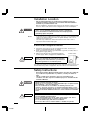
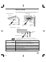
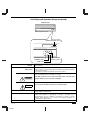
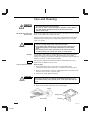
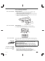
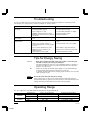
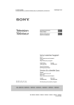
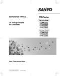
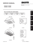
INSTRUCTION MANUAL
Split System Heat Pump
Wall-mounted type
Ceiling-mounted type
Recessed type
KHS2432
THS2432
XHS2432
KHS3632
THS3632
XHS3632
THS4232
XHS4232
Save This Instruction Manual
Pub. OI-85464189212002
©SANYO 2003
Features
These air conditioners are equipped with a cooling function. Details on this function are provided below; refer
to these descriptions when using the air conditioner.
•
Microprocessor Controlled Operation
The interior compartment of the remote control
unit contains several features to facilitate
automatic operation, and is logically displayed
for easy use.
•
Simple One-touch Wireless Remote Control
The remote control unit has several features to
facilitate automatic operation.
•
24-hour clock with ON/OFF Program Timer
The wireless remote controller allows you to set
up a wide variety of time based operations.
Such functions include automatic on/off with
time settings, same time on/off every day, on
timer and off timer.
•
1-Hour OFF Timer
This timer turns off the unit one hour after the
button is pressed.
•
Night Setback
Pressing the Night Setback button changes the
setting of the room temperature thermostat so
that you do not experience excessive cooling or
heating when sleeping.
•
Automatic and 3-step Fan Speed
Auto/High/Medium/Low
2
oi212001
•
Air Sweep Control
The flaps move up and down in the air outlet,
directing air in a sweeping motion around the
room, providing comfort in every corner.
•
Automatic Restart Function for Power Failure
Even when power failure occurs, preset
programmed operation can be reactivated once
power resumes.
•
Anti-Mold Filter
This unit is equipped with an anti-mold filter
that inhibits the growth of mold and bacteria.
OI-212-02EG
Contents
Page
Features.................................................................................................................. 2
Product Information .............................................................................................. 3
Warning Symbols.................................................................................................. 3
Installation Location.............................................................................................. 4
Electrical Requirements ........................................................................................ 4
Safety Instructions ................................................................................................ 4
Names of Parts ...................................................................................................... 5
Using the Remote Control Unit ......................................................................... 11
Operation with the Remote Control Unit.......................................................... 13
1. Automatic Operation ............................................................................ 13
2. Manual Operation ................................................................................. 14
3. Adjusting the Fan Speed...................................................................... 15
4. Fan Only................................................................................................. 16
5. Night Setback Mode ............................................................................ 16
Special Remarks ................................................................................................. 18
Setting the Timer ................................................................................................ 18
Using the 1-Hour OFF Timer.............................................................................. 20
Adjusting the Airflow Direction ......................................................................... 21
Operation without the Remote Control Unit .................................................... 21
Care and Cleaning............................................................................................... 22
Troubleshooting................................................................................................... 24
Tips for Energy Saving....................................................................................... 24
Operating Range ................................................................................................. 24
Product Information
The following information is useful when calling a service person. Please fill
in the blanks below. The model and serial numbers are on the nameplate at
the bottom of the cabinet.
Serial No.
Model No.
Date of purchase
Dealer’s address
Phone number
Warning Symbols
The following symbols are used in this manual to alert to potentially
dangerous conditions to users and service personnel using this appliance:
This symbol refers to a hazard or unsafe
practice which can result in severe personal
injury or death.
CAUTION
OI-212-03EG
oi212001
This symbol refers to a hazard or unsafe
practice which can result in personal injury
or product or property damage.
3
Installation Location
We recommend that this air conditioner be installed properly by
qualified installation technicians in accordance with the Installation
Instructions provided with the unit.
Before installation, check that the voltage of the electric supply in your
home or office is the same as the voltage shown on the nameplate.
•
•
•
•
Avoid:
Do not install this air conditioner where there are fumes or flammable
gases, or in an extremely humid space such as a greenhouse.
Do not install the air conditioner where excessively high heatgenerating objects are placed.
To protect the air conditioner from heavy corrosion, avoid installing the
outdoor unit where salty sea water can splash directly onto it or in
sulphurous air near a spa.
The unit may malfunction when the receiver in the indoor unit is
exposed to the inverter lamp light.
•
•
Electrical Requirements
1. All wiring must conform to the local electrical codes. Consult your
dealer or a qualified electrician for details.
2. Each unit must be properly grounded with a ground (or earth) wire or
through the supply wiring.
3. Wiring must be done by a qualified electrician.
Power mains
•
Power supply: 60 Hz, single-phase, 230/208 volts.
To warm up the system, the power mains must be
turned on at least five (5) hours before operation.
Leave the power mains ON unless you will not be
using this appliance for an extended period.
CAUTION
ON
For ceiling-mounted and recessed-type indoor units, the flaps move for one
minute when the power is supplied to the unit. This is not a malfunction.
Safety Instructions
Read this Instruction Manual carefully before using this air conditioner.
If you still have any difficulties or problems, consult your dealer for
help.
This air conditioner is designed to give you comfortable room
conditions. Use this only for its intended purpose as described in this
Instruction Manual.
•
•
•
•
•
CAUTION
•
•
•
•
4
oi212001
Never touch the unit with wet hands.
Never use or store gasoline or other flammable vapor or liquid near the
air conditioner — it is very dangerous.
This air conditioner has no ventilator for intaking fresh air from
outdoors. You must open doors or windows frequently when you use
gas or oil heating appliances in the same room, which consume a lot of
oxygen from the air. Otherwise there is a risk of suffocation in extreme
cases.
Do not turn the air conditioner on and off from the power mains switch.
Use the ON/OFF operation button.
Do not stick anything into the air outlet of the outdoor unit. This is
dangerous because the fan is rotating at high speed.
Do not let children play with the air conditioner.
Do not cool the room too much if babies or invalids are present.
OI-212-04EG
Names of Parts
Each air conditioner shown below consists of an indoor unit and an outdoor
unit. You can control the air conditioner with the remote control unit.
Ceiling-mounted type
Recessed type
Air outlet
Air
intake
Air outlet
Drain tube
Drain tube
Remote
control
unit
Refrigerant
tubes
Wall-mounted type
Air intake
Remote control
unit
Refrigerant
tubes
Air intake
Refrigerant
tubes
Air outlet
Remote control unit
NOTE
Air intake
Air outlet
Remote control unit
Refrigerant tubes
Drain tube
Outdoor (condensing) unit
OI-212-05EG
oi212001
Drain
tube
This illustration is based on the external view of a standard model.
Consequently, the shape may differ from that of the air conditioner which
you have selected.
The return air in the room is drawn into this section and passes through
air filters which remove dust and foreign particles.
Conditioned air is returned to the room through the air outlet (ceiling
and wall-mounted type) or four air outlets (Recessed type).
The direction of airflow can be adjusted as desired using the remote
control unit.
The wireless remote control unit controls power ON/OFF, operation
mode selection, temperature, fan speed, timer setting, and air sweeping.
The indoor and outdoor units are connected by copper tubes through
which refrigerant gas flows.
Moisture in the room is condensed and drains off by means of this tube.
The outdoor unit contains the compressor, fan motor, heat exchanger
coil, and other electrical components.
5
Unit Display and Operation Selector
Recessed type
OPERATION
lamp
Ceiling-mounted type
TIMER
lamp
Recessed type
STANDBY
lamp
Remote
control
receiver
Ceiling-mounted type
Operation selector
ADDRESS
1.TEST RUN
2.PCB CHK(ON)
3.RCU MAIN (OFF)
4.(OFF)
Finger-hold
SERVICING ADDRERS NORM./ SWEEP ON/OFF
switches
switch
HOLD button operation
switch
button
Air intake grille
ADDRESS
1.TEST RUN
2.PCB CHK(ON)
3.RCU MAIN (OFF)
4.(OFF)
Air intake
grille
SERVICING ADDRESS NORM./ SWEEP ON/OFF
switches
switch
HOLD button operation
button
switch
Air filter
Operation selector
6
oi212001
OI-212-06EG
Unit Display and Operation Selector (continued)
INDOOR UNIT
REMOTE CONTROL receiver
STANDBY
OPERATION lamp
STANDBY lamp
Operation selector
TIMER lamp
REMOTE CONTROL
receiver
Operation selector
This section picks up infrared signals from the remote control unit
(transmitter).
ON position
This position is for operating the air conditioner with the wireless
remote control unit.
The selector should normally be set in this position.
OFF position
Switch the selector to the OFF position if you are not going to use
the air conditioner for a few days or longer.
The OFF position does not disconnect the power. Use the main
power switch to turn off power completely.
TEST position
CAUTION
OPERATION lamp
STANDBY lamp
TIMER lamp
OI-212-07EG
oi212001
This position is used only when servicing the air conditioner.
Do not set at the TEST position for normal operation.
This lamp lights when the system is in the continuous AUTO,
HEAT, COOL or FAN mode.
This lamp lights when the system is warming up for heating and
when the system is defrosting. To keep a constant room
temperature, the air conditioner continues to supply a gentle
breeze when warming up or when the heating operation is
paused by the thermostat.
This lamp lights when the system is being controlled by the timer.
7
Remote Control Unit (Display)
Displayed when main unit sensor is in use
“ROOM TEMP” is displayed when the temperature setting has
not been made.
“TEMP” is displayed when setting temperature.
Displayed when transmitting data
Displayed when temperature is
shown
Displayed when the temperature
setting is at the upper or lower
allowable limit
Displayed when setting timer
Symbols
(1) Operation mode
AUTO.......................................
(3) Set temperature
60 – 86 °F
When set to 82 °F ...........
F
Current temperature
indication .........................
COOLING.................................
(4) Timer
HEATING .................................
FAN ..........................................
24-hour clock with ON/OFF
Program Timer .......................
24-hour ON Timer ..................
ON
24-hour OFF Timer.................
OFF
Automatic operation ..............
1-hour OFF Timer...................
1HR.
HIGH ........................................
(5) NIGHT SETBACK ....................
MEDIUM..................................
(6) Confirmation of
transmission ...........................
(2) Fan speed
LOW.........................................
(7) Sweep indication....................
8
OI-212-08EG
oi212001
AAAAAA
Remote Control Unit
Sensor
Transmitter
Display
(Cover closed)
NIGHT SETBACK button
ON/OFF operation button
1 HR. TIMER button
Temperature setting buttons
MODE selector button
FAN SPEED selector button
FLAP button
TIMER SELECT button
TIMER AND PRESENT TIME
setting buttons
PROGRAM button
ADDRESS switch
ACL button
SENSOR button
Battery compartment
(Pull off the cover to expose the
batteries.)
NOTE
Transmitter
When you press the buttons on the remote control unit, the
mark
appears in the display to transmit the setting changes to the receiver in
the air conditioner.
Sensor
A temperature sensor inside the remote control unit senses the room
temperature.
Display
Information on the operating conditions is displayed while the remote control
unit is switched on. If the unit is turned off, only the mode that was set
previously is still displayed.
NIGHT SETBACK button
For details, see “Night Setback Mode”. When you press this button in the
COOL or HEAT mode, the
mark appears in the display, and the remote
control unit automatically adjusts the set temperature to save energy.
Temperature setting
buttons (TEMP.)
ON/OFF operation button
Timer and Present Time
setting buttons
OI-212-09EG
The illustration above pictures the remote control unit after the cover has been
lowered and removed.
Press the
Press the
button to increase the set temperature.
button to reduce the set temperature.
This button is for turning the air conditioner on and off.
First, press the program button to select the mode you want.
Each time you press the “HH” button, the hours advance by one.
Each time you press the “MM” button, the minutes advance by one.
9
Remote Control Unit (continued)
Program button
For details, see “Setting the Timer”.
Press this button to select the mode you want to program.
TIMER SELECT button
No display : The timer does not operate.
: The air conditioner stops at the set time.
: The air conditioner starts at the set time.
: The air conditioner stops and starts, or starts and stops, at the
set times every day.
MODE selector button
(AUTO)
Use this button to select the AUTO, HEAT, COOL or FAN mode.
: When this setting is selected, the air conditioner calculates the
difference between the thermostat setting and the room temperature
and automatically switches to the “COOL” or “HEAT” mode as
appropriate.
: The air conditioner makes the room warmer.
: The air conditioner makes the room cooler.
: The air conditioner works only as a circulation fan.
(HEAT)
(COOL)
(FAN)
FLAP button
Press this button to select the sweep function, which moves the flap up and
down automatically.
: The flap moves up and down automatically.
: The air conditioner automatically decides the fan speeds.
: High fan speed
: Medium fan speed
: Low fan speed
FAN SPEED selector button
1 HR. TIMER button
(1-HOUR OFF TIMER)
ACL button (ALL CLEAR)
ADDRESS switch
: When you press this button, regardless of whether the unit is
operating or stopping, the unit operates for one hour and then
shuts down.
Puts the remote control unit into pre-operation status. Always press this
button after replacing the batteries.
•
•
Change the address switch to prevent mixing of signals from remote control
units when two Sanyo air conditioners are installed next to each other.
Normally, the remote control address switch is set to A. For the second
indoor unit, both addresses of the remote control unit and the indoor unit
must be changed. The second remote control unit address must be changed
to B by breaking off the tab ”A“. And the second indoor unit address must
be changed from 1 to 2 by switching the slide switch in the indoor unit. For
more information, please contact the dealer where you made the purchase.
Normally, the tabs on the remote control unit should not be bent.
SENSOR button
When you press this button (use a small-tipped object such as a ballpoint
mark will appear at the display. And the room temperature is
pen), the
detected by the sensor which is built into the indoor unit and the air
conditioner is controlled accordingly.
NOTE
If the remote control is located near a heat source, such as a space heater or
in direct sunlight, press the SENSOR button to switch to the sensor on the
indoor unit.
NOTE The remote control unit sends the temperature signal to the air conditioner regularly at five minute intervals.
If the signal from the remote control unit stops for more than ten minutes due to the loss of the remote
control unit or other trouble, the air conditioner will switch to the temperature sensor which is built into
the indoor unit and control the room temperature. In these cases, the temperature around the remote
control unit may differ from the temperature detected at the air conditioner’s position.
10
OI-212-10EG
Using the Remote Control Unit
How to Install Batteries
1. Slide the cover in the direction indicated by the arrow
and remove it.
2. Install two AAA alkaline batteries. Make sure the
batteries point in the direction marked in the battery
compartment.
3. Use a thin object such as the tip of a pen to press the
ACL button.
ACL button
NOTE
•
•
•
•
How to Use the Remote
Control Unit
The batteries last about six months, depending on how much you use the
remote control unit. Replace the batteries when the remote control unit’s
display fails to indicate, or when the remote control cannot be used to
change the air conditioner’s settings.
Use two fresh leak-proof type-AAA alkaline batteries.
In replacing batteries, follow the instructions as mentioned in the
sub-section “How to Install Batteries”.
If you do not use the remote control unit more than 1 month, take out the
batteries.
When using the remote control unit, always point the unit’s transmitter
head directly at the air conditioner’s receiver.
Air conditioner
(Indoor unit)
Receiver
(Transmitter head)
Remote control
unit
Remote Control Unit
Installation Position
DO NOT
The remote control unit may be operated either from a non-fixed position
or from a wall-mounted position. To ensure that the air conditioner operates
correctly, DO NOT install the remote control unit in the following places:
•
•
•
•
•
•
•
OI-212-11EG
In direct sunlight
Behind a curtain or other places where it is covered
More than 26 feet (8 m) away from the air conditioner
In the path of the air conditioner’s airstream
Where it may become extremely hot or cold
Where it may be subject to electrical or magnetic noise
Where there is an obstacle between the remote control unit and air
conditioner (since a check signal is sent from the remote control unit every
5 minutes)
11
Using the Remote Control Unit (continued)
Mounting the Remote
Control Unit
Truss-head
tapping screws
5/32 x 5/8 “ (4 x 16 mm)
(supplied)
Press
Remote
control
unit holder
When attaching to wall
Hook
1) Confirm the indoor unit beeps when the ON/OFF button is pressed at the
wall location where the remote control unit is to be attached, then attach
the holder to the wall.
2) When taking out the remote control unit, pull it from the holder.
When using the remote
control unit
•
•
Point the transmitter on the remote control unit at the sensor on the
indoor unit when operating the remote control unit and the air conditioner.
Do not place objects which may block the transmitted signals between
the receiver and the remote control unit.
Truss-head
tapping screws
5/32 x 5/8 “ (4 x 16 mm)
(supplied)
Holder
Remote
control
unit holder
Securing the remote
control unit to prevent theft
1) Attach the holder to the wall with one screw in the upper hole only.
2) Remove the cover from the remote control unit, and then remove the
batteries. Next, place the remote control unit in the holder.
3) Secure both the remote control unit and the holder to the wall with another
screw through the lower hole.
4) Put the batteries back in the remote control unit, and then replace the
cover.
12
OI-212-12EG
Operation with the Remote
Control Unit
1. Automatic Operation
STEP 2
STEP 1
NOTE
Check that the circuit breaker on the power panel is turned on and that the
operation selector of the indoor unit is in the ON position.
is selected and the unit is set using the
When Automatic operation mode
steps below, the air conditioner operates automatically and brings the room
to the desired temperature simply by pressing the ON/OFF operation
button.
STEP 1
Press the MODE selector to
.
STEP 2
Press the ON/OFF operation button.
To stop the air conditioner, press the ON/OFF operation button again.
NOTE
•
•
•
OI-212-13EG
oi212001
To change the temperature setting, press the temperature setting
buttons and change the setting to the desired temperature.
The
indicates the upper limit for the temperature setting and the
indicates the lower limit.
The temperature setting changes by two degrees each time one of the
TEMP. buttons is pressed.
Although the fan speed is set automatically, you can change the fan
speed by pressing the FAN SPEED selector button as shown below.
13
Operation with the Remote Control Unit (continued)
2. Manual Operation
STEP 2
STEP 3
STEP 1
STEP 4
STEP 5
NOTE
Check that the circuit breaker on the power panel is turned on and that the
operation selector of the indoor unit is in the ON position.
If the automatic operation settings of the unit are not satisfactory, press the
setting buttons below to change the settings as desired.
STEP 1
Press the MODE selector button and select the desired
mode.
For heating operation
→
For cooling operation
→
STEP 2
To start the air
operation button.
STEP 3
Press the TEMP. setting buttons to change
temperature setting to the desired temperature.
Adjustable temperature range:
86 °F max.
60 °F min.
STEP 4
Set the FAN SPEED selector button to the setting you
want.
NOTE
If the fan speed is set to
(Automatic), the fan speed
switches automatically according to the difference
between the actual room temperature and the
temperature setting.
STEP 5
Press the FLAP button and set the airflow direction as
desired.
(Refer to ‘‘Adjusting the Airflow Direction’’ on
page 21.)
conditioner,
press
the
ON/OFF
the
To stop the air conditioner, press the ON/OFF operation button again.
14
oi212001
OI-212-14EG
Operation with the Remote Control Unit (continued)
NOTE
•
Choose the best position in the room for the remote control unit, which
also acts as the sensor for room comfort and transmits the operating
instructions. Once you’ve found this best position, always keep the
remote control unit there.
•
This appliance has a built-in 3-minute time delay circuit to ensure
reliable operation. When the operation button is pressed, the
compressor will start running within three minutes. In the event of
power failure, the unit will stop. When the power is restored, the unit
will restart automatically after three minutes.
3. Adjusting the
Fan Speed
A. Automatic
Simply set the FAN SPEED selector button to the
position.
A microcomputer in the air conditioner controls the fan speed automatically
mode is selected. When the air conditioner starts operating,
when the
the difference between the room temperature and the set temperature is
detected by the microcomputer which then automatically switches the fan
speed to a suitable level.
Cooling mode:
When difference between
room temperature and set
temperature is
FAN SPEED
4 °F and over
High
Between 4 °F and 2 °F
Medium
Below 2 °F
Low
When difference between
room temperature and set
temperature is
FAN SPEED
4 °F and over
High
Below 4 °F
Medium
Heating mode:
NOTE
B. Manual
OI-212-15EG
oi212001
The above table assumes that the sensor in the remote control is being
indicator is on),
used. If the sensor in the indoor unit is being used (the
actual operation may differ slightly from the operation described in the
table.
(Refer to ‘‘SENSOR button’’ on page 10.)
If you want to adjust fan speed manually during operation, just set the FAN
SPEED selector button as desired by following STEP 4 on page 14. [
,
, or
]
15
Operation with the Remote Control Unit (continued)
4. Fan Only
STEP 2
STEP 1
STEP 3
If you want to circulate air without any temperature control, follow these
steps:
STEP 1: Press the MODE selector button to switch to the fan mode.
( )
STEP 2: Press the ON/OFF button.
STEP 3: Press the FAN SPEED selector button to select the fan speed of
,
, or
).
your choice (
5. Night Setback Mode
Night Setback Mode is used for saving energy.
Press the NIGHT SETBACK button during operation.
The
mark appears in the display.
To release the night setback function, press the NIGHT SETBACK button
again.
NOTE
16
oi212001
The night setback mode cannot be used during automatic operation.
OI-212-16EG
Operation with the Remote Control Unit (continued)
A. Cooling Mode:
( )
When the night setback mode is selected, the air conditioner
automatically raises the temperature setting 2 °F when 30 minutes
have passed after the selection was made, and then another 2 °F after
another 30 minutes have passed, regardless of the indoor
temperature when night setback was selected. This enables you to
save energy without sacrificing comfort. This function is convenient
when gentle cooling is needed.
2 °F
Set
temperature
2 °F
30 min.
Pressing the
NIGHT SETBACK
button
B. Heating Mode:
( )
30 min.
Time
When the night setback mode is selected, the air conditioner
automatically lowers the temperature setting 4 °F when 30 minutes
have passed after the selection was made, and then another 4 °F after
another 30 minutes have passed, regardless of the indoor
temperature when night setback was selected. This enables you to
save energy without sacrificing comfort. This function is convenient
when gentle heating is needed.
Set
temperature
4 °F
4 °F
Pressing the
NIGHT SETBACK
button
OI-212-17EG
oi212001
30 min.
30 min.
Time
17
Special Remarks
Power failure
during operation
•
In case of power failure, the unit will stop. When the power is restored, the
unit will restart automatically after three minutes.
Remote Control Unit
•
The remote control unit transmits the setting condition to the air
conditioner regularly at three minute intervals.
Setting the Timer
3
4
2
1
1.
How to set the
present time
(Example) To set to 9:10 pm.
Operation
1. Press the Program button (
three times.
2.
•
•
2. How to set the OFF time
Indication
)
Press the HH button until PM 9 is
displayed.
Press the MM button until 10 is
displayed.
The time indication alone blinks.
The display will automatically
stop blinking except for the “:”
symbol after 10 sec.
(Example) To stop the air conditioner at 11:30 pm.
1. Press the Program button (
once.
2.
•
•
)
Press the HH button until PM 11 is
displayed.
Press the MM button until 30 is
displayed.
The timer
indication blinks
and present OFF time is shown.
The display will change
automatically back to show the
present time after 10 sec.
3. Press the ON/OFF button to start the The present time is displayed.
air conditioner.
4. Press the TIMER SELECT button to
set OFF time.
18
The present time and
displayed.
are
OI-212-18EG
Setting the Timer (continued)
3.
How to set the ON time
(Example) To start operation at 7:10 am.
Operation
1. Press the Program button (
twice.
2.
•
•
Indication
)
Press the HH button until AM 7 is
displayed.
Press the MM button until 10 is
displayed.
The timer
indication blinks
and present ON time is shown.
The display will change
automatically back to show the
present time after 10 sec.
3. Press the ON/OFF button to start the The present time is displayed.
air conditioner.
4. Press the TIMER SELECT button to
set ON time.
4.
How to set a program
for daily ON/OFF
operation
The present time and
displayed.
are
(Example) To start operation at 7:10 am. and stop the air conditioner at
11:30 pm.
7:10 am
ON
11:30 pm
OFF
Present
time
1. Set the timer ON/OFF times as
shown in 2 and 3.
OFF
time
2. Press the ON/OFF button to start the
air conditioner.
3. Press the TIMER SELECT button to
set the ON/OFF combination timer.
ON
time
NOTE
Programed
daily
ON/OFF
NOTE
OI-212-19EG
The present time PM 9:10 and
are displayed.
When the Daily ON/OFF program is set to start the air conditioner
before the ON time setting, the
indications appear on the
display.
On the other hand, when the Daily ON/OFF program is set to start the
air conditioner after the ON time setting, the
indications
appear on the display. Thus, these indications show the timer program
which will operate next.
You can check the timer ON/OFF times after you have set them by
pressing the PROGRAM button.
19
Using the 1-Hour OFF Timer
1.
1-Hour OFF Timer
This function causes the unit to operate for one hour and then stop, regardless
of whether the unit is on or off when this button is pressed.
The
indicator in the display indicates that this function is operating.
Setting procedure:
Regardless of whether the unit is operating or stopped, press the 1 HR. TIMER
button.
appears in the display.
Cancellation procedure:
Press the ON/OFF operation button to turn the unit off, wait for the unit to stop
operating, and then press the ON/OFF operation button again. The 1-Hour Timer
function is now cancelled and the unit operates normally.
NOTE
•
If, while the 1-Hour Timer function is operating, the 1 HR. TIMER button is
pressed once to cancel the function and then again, the unit continues to
operate for one hour from that point in time and then stops.
2. Operation Together
with the Program Timer
•
The 1-Hour OFF Timer setting is given priority over the daily program
setting.
•
It is not possible to use the OFF Timer and 1-Hour OFF Timer together.
Whichever function is set last takes precedence.
If the 1 HR. TIMER button is pressed while the TIMER OFF function operates,
OFF Timer is cancelled and the unit will stop operating one hour later.
20
OI-212-20EG
Adjusting the Airflow Direction
A. Horizontal (Wall-mounted type only)
The horizontal airflow can be adjusted by moving the vertical vane to the
left or right.
Indoor unit
(Wall-mounted type)
Left
Right
Vertical
vane
B. Vertical
Confirm that the remote control unit has been turned on. Press the FLAP
button to start the flap moving up and down ( ). If you want to stop the
flap movement and to direct the air in the desired direction, press the FLAP
button again. In the COOL mode, don’t direct the flap down more than 30 °
(KHS, THS Types), or leave it in the vertical position (XHS Type), otherwise
condensation may drip onto the floor. Zone ‘‘A’’ (KHS, THS Types) and any
position other than vertical (XHS Type) are the recommended flap positions
for cooling.
30°
Zone
‘‘A’’
for
COOLING
CAUTION
Do not move the flap with your hands.
Up
Air outlet
grille
INDOOR UNIT
Flap
Down
Operation without the Remote
Control Unit
If you have lost the remote control unit or it is not working, follow the steps
below.
1. When the air conditioner is stopped.
If you want to turn on the air conditioner, switch the operation selector to
the OFF position, and then to the ON position.
STANDBY
Operation
selector
Flap
(Wall-mounted type)
OI-212-21EG
oi212001
NOTE
The set temperature and fan speed are automatically set at the
last selection before stopping.
2. When the air conditioner is running.
If you want to turn off the air conditioner, switch the operation selector to
the OFF position.
21
Care and Cleaning
1. For safety, be sure to turn the air conditioner off and also to
disconnect the power before cleaning.
2. Do not pour water or spray detergent on the indoor unit to clean it.
This will damage the internal components and may cause an
electric shock or fire.
Air Intake and outlet side
(Indoor Unit)
Clean the air intake and outlet side of the indoor unit with a vacuum cleaner
brush, or wipe them with a clean soft cloth.
If these parts are stained, use a clean cloth moistened with a mild liquid
detergent. When cleaning the air outlet side, be careful not to force the
vanes out of place.
CAUTION
Air filter
NOTE
How to remove the filter
1. Never use solvents or harsh chemicals when cleaning the indoor
unit. Do not wipe plastic parts using very hot water.
2. Some metal edges and the fins are sharp and may cause injury if
handled improperly; be especially careful when you clean these
parts.
3. The internal coil and other components of the outdoor unit must
be cleaned every year. Consult your dealer or service center.
The air filter collects dust and other particles from the air and should be
cleaned about once every six months (Recessed type) or two weeks
(ceiling-mounted type and wall-mounted type). If the filter gets blocked, the
efficiency of the air conditioner drops greatly.
The frequency with which the filter should be cleaned depends on the
environment in which the unit is used.
Recessed type:
1. Remove the bolt screw on each side out of the latch using a
screwdriver. (After cleaning, be sure to reattach the two bolt screws.)
2. Press on the two latches of the air intake grille with your thumbs in the
direction of the arrow to open the grille.
3. Open the air intake grille downward.
CAUTION
When cleaning the air filter, never remove the safety string. If it is
necessary to remove it for servicing and maintenance inside, be sure
to reinstall the safety string securely (hook on the grille side) after the
work.
4. Remove the air filter attached to the air intake grille.
Latch
Safety string
Air intake
grille
Bolt screw
22
oi212001
Air filter
OI-212-22EG
Care and Cleaning (continued)
How to remove the filter
Ceiling-mounted type:
1. Remove the bolt screws on the latch using a screwdriver. (After
cleaning, be sure to reattach the two bolt screws.)
2. Take hold of the two latches on the air intake grille and press them to
the rear, and the grille will open downward.
3. Take hold of the finger-hold on the air filter, first lift it and then pull it
toward you to release it from the catch.
Catch
Latch
Air filter
Air intake grille
Air filter finger-hold
How to remove the filter
Wall-mounted type
1. Move the flap on the air outlet grille to its lowest position.
2. Hold the air filter by the tab at the bottom, and pull downward.
Air filter
Pull down
How to clean the filter
Use a vacuum cleaner to remove light dust. If there is sticky dust on the
filter, wash the filter in lukewarm, soapy water, rinse it in clean water, and
dry it.
Outdoor Unit
1. Certain metal edges and the condenser fins are sharp and may
cause injury if handled improperly; special care should be taken
when you clean these parts.
2. Periodically check the outdoor unit to see if the air outlet or air
intake is clogged with dirt or soot.
3. The internal coil and other components of the outdoor unit must
also be cleaned periodically. Consult your dealer or service center.
CAUTION
Care: After a Prolonged Idle
Period
Care: Before a Prolonged Idle
Period
Check the indoor and outdoor unit air intakes and outlets for blockage; if
there is a blockage, remove it.
•
•
•
•
OI-212-23EG
oi212001
Operate the fan for half a day to dry out the inside.
Disconnect the power supply and also turn off the breaker.
Clean the air filter and replace it in its original position.
Outdoor unit internal components must be checked and cleaned
periodically. Contact your local dealer for this service.
23
Troubleshooting
If your air conditioner does not work properly, first check the following points before requesting service.
If it still does not work properly, contact your dealer or service center.
Trouble
Air conditioner does not
run at all.
Possible Cause
1. Power failure.
2. Leakage breaker tripped.
3. Line voltage is too low.
4. ON/OFF operation button is OFF.
5. Batteries in remote control unit have
run down.
1. Obstruction in front of condenser
coil.
1. Dirty or clogged air filter.
Compressor runs but
soon stops.
Poor cooling
performance.
2. Heat source (cooker, heater, or
electrical appliance) or many people
in room.
3. Doors and/or windows are open.
4. Obstacle near air intake or air
discharge port.
5. Thermostat is set too high.
1.
2.
3.
4.
5.
Remedy
Restore power.
Contact service center.
Consult with electrician or dealer.
Press the button again.
Replace batteries.
1. Remove obstruction.
1. Clean the air filter to improve the air
flow.
2. Eliminate heat source if possible.
3. Shut them to keep the heat out.
4. Remove it to ensure good air flow.
5. Set the temperature lower.
Tips for Energy Saving
Do not
•
•
Do
•
•
NOTE
Block the air intake and outlet of the unit. If either is obstructed, the
unit will not work well, and may be damaged.
Let direct sunlight into the room. Use sunshades, blinds or curtains. If
the walls and ceiling of the room are warmed by the sun, it will take
longer to cool the room.
Always try to keep the air filter clean. (Refer to ‘‘Care and Cleaning.’’)
A clogged filter will impair the performance of the unit.
To prevent conditioned air from escaping, keep windows, doors and any
other openings closed.
Should the power fail while the unit is running
If the power supply for this unit is temporarily interrupted the unit will
automatically resume operation (once the power is restored) with the same
settings that were in effect before the power was interrupted.
Operating Range
The air conditioner is operable within the temperature ranges listed below:
COOLING
HEATING
24
oi212001
Temperature
Max.
Min.
Indoor air temperature
95 °F DB/71 °F WB
67 °F DB/57 °F WB
Outdoor air temperature
115 °F DB
23 °F DB
Max.
Min.
80 °F DB/67 °F WB
— PB/— WB
75 °F DB/65 °F WB
17 °F DB/15 ° F WB
OI-212-24EG
SANYO FISHER COMPANY
A DIVISION OF SANYO NORTH AMERICA CORPORATION
21605 Plummer Street
Chatsworth, CA 91311 U.S.A.
oi212001
In Canada
SANYO Canada Inc.
300 Applewood Crescent,
Concord, Ontario,
L4K 5C7, Canada