1
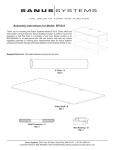
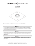
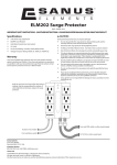
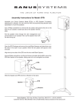
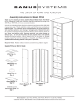
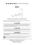
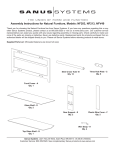
Step 5: Add 7” Pillars
Thread a 7” Pillar (g) onto each exposed Shelf Connector (a). Place a Grommet (d) in each wire management hole in the Bottom and
Middle Shelf (k). See Diagram 5 for assistance.
Diagram 5
Assembly Instructions for Model: AFV48
a
k
Thank you for choosing Accurate Furniture from Sanus Systems!
g
Safety Warning: If you do not understand these directions, or have any doubts about the safety of the installation, please call a qualified
contractor or contact Sanus at 800.359.5520 or www.sanus.com. Check carefully to make sure that there are no missing or defective
parts. Our customer service representatives can quickly assist you with installation questions and missing or damaged parts. Replacement parts for products purchased through authorized dealers will be shipped directly to you. Never use defective parts. Improper installation may cause damage or serious injury. Do not use this product for any purpose that is not explicitly specified by Sanus Systems.
Sanus Systems can not be liable for damage or injury caused by incorrect mounting, incorrect assembly, or incorrect use. Please call
Sanus Systems before returning products to the point of purchase.
d
Required Tools:
k
Supplied Parts and Hardware: Some parts not shown as actual size*
(10) Shelf Connector - a
(6) Top Bolt - b
(4) Grommet - d
(2) Spacer - e
(4) 7” Pillar - g*
(6) 3” Pillar - h*
(6) Foot - c
Step 6: Add Top Shelf
To add the Top Shelf (j), insert the front two Top Bolts (b) through the holes in the front of the Top Shelf, the Front Brace (l) and thread
them into the 7” Pillars (g). See Detailed View A for assistance. Insert the back two Top Bolts through the holes in the back of the Top
Shelf, the Spacers (e), and thread them into the 7” Pillars. See Diagram View B for assistance. Tighten each Top Bolt with the Allen Key
(f).
Detailed View A
(1) Allen Key - f
Detailed View B
Diagram 6
b
b
j
j
l
e
g
front
(1) Top Shelf - j*
(2) Bottom & Middle Shelf - k*
g
Sanus Systems 2221 Hwy 36 West, Saint Paul, MN 55113 5.27.05
Customer Service: 800.359.5520. See complementary Sanus products at www.sanus.com
(6) 9” Pillar - i*
(1) Front Brace - l*
Sanus Systems 2221 Hwy 36 West, Saint Paul, MN 55113 5.27.05
Customer Service: 800.359.5520. See complementary Sanus products at www.sanus.com
Step 1: Foot Assembly
Step 3: Add 9” Pillars
Thread a Foot (c) into each 3” Pillar (h) until tight. Thread a Shelf Connector (a) into the other end of the 3” Pillar until tight. Repeat the
process for each remaining 3” Pillar. See Diagram 1 for assistance.
Thread a 9” Pillar (i) onto each exposed Shelf Connector (a) until tight. Once the 9” Pillars are hand tight, thread a Shelf Connector
into the top of the four 9” Pillars. See Diagram 3 for assistance.
Diagram 1
Diagram 3
a
a
i
a
k
h
c
Step 2: Add Bottom Shelf
Step 4: Add Middle Shelf
Insert each Foot Assembly through the Bottom Shelf (k) as shown in Diagram 2.
Place the Middle Shelf (k) on the 9” Pillars (i). A Shelf Connector (a) should be protruding above the Middle Shelf in each corner. Place
a Top Bolt (b) through the Middle Shelf and thread it into each middle pillar. See Diagram 4 for assistance. Tighten each Top Bolt with
the Allen Key (f).
Diagram 2
Diagram 4
k
b
k
a