1
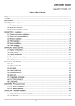
CONFIDENTIAL
PDP-027-1(Module Format)
Issues:Nov.07.03
Version:1.0
50“ PDP
SERVICE MANUAL
MODEL: GTW-P50M603
PANEL: Samsung(VVES50HW-XD01--)
CONTENTS
1. IMPORTANT SAFETY PRECAUTIONS …………..1-2
2. SPECIFICATION
…………………………………2-10
3. FACTORY & ELECTRONIC ADJUSTMENT……...3-7
4. BLOCK DIAGRAM
………………………………...4-4
5. TROUBLE SHOOTING GUIDES
……….…….….5-6
6. B.O.M. OF BOARD ASSEMBLY ………………....6-18
7. P.C. BOARD TOP VIEW
..…………………….…..7-9
8. ELECTRONIC MODULE LIST …………….……..8-1
9. EXPLODED VIEW
………………………….……..9-1
10.PACKAGING LIST ……………..…………..……10-1
IMPORTANT SAFETY PRECAUTIONS
VER1.0
1. Before returning an instrument to the customer, always make a safety check of the entire instrument,
including, but not limited to, the following items.
a. Be sure that no built-in protective devices are defective and/or have been defeated during servicing. (1)
Protective shields are provided on this chassis to protect both the technician and the customer. Correctly
replace all missing protective shields, including any removed for servicing convenience. (2) When reinstalling
the chassis and/or other assembly in the cabinet, be sure to put back in place all protective devices, including,
but not limited to, nonmetallic control knobs, insulating fish papers, adjustment and compartment
covers/shields, and isolation resistor/capacitor networks. Do not operate this instrument or permit it to be
operated without all protective devices correctly installed and functioning.
b. Be sure that there are no cabinet openings through which an adult or child might be able to insert their
fingers and contact a hazardous voltage, Such opening include, but are not limited to, (1) spacing between
the picture tube and the cabinet mask, (2) excessively wide cabinet ventilation slots, and (3) an improperly
fitted and/or incorrectly secured cabinet back cover.
c. Leakage Current Hot Check—With the instrument completely reassembled, plug the AC line cord directly
into a 120V AC outlet. (Do not use an isolation transformer during this test.) Use a leakage current tester or a
metering system that complies with American National Standards Institutes (ANSI) C101.1 Leakage Current
for Appliances and Underwriters Laboratories (UL) 478. With the instrument AC switch first in the ON position
and then in the OFF position, measure from a known earth ground (metal water pipe, conduit, etc.) to all
exposed metal parts of the instrument (antennas, handle bracket, metal cabinet, screw heads, metallic
overlays, control shafts, etc.), especially any exposed metal parts that offer an electrical return path to the
chassis. Any current measured must not exceed 3.5 milliamp. Reverse the instrument power cord plug in the
outlet and repeat test. ANY MEASUREMENTS NOT WITHIN THE LIMITS SPECIFIED HEREIN INDICATE A
POTENTIAL SHOCK HAZARD THAT MUST BE ELIMINATED BEFORE RETURNING THE INSTRUMENT
TO THE CUSTOMER.
AC Leakage Test
LEAKAGE
CURRENT
TESTER
DEVICE
UNDER
TEST
(READING
SHOULD NOT
BE ABOVE
3.5mA)
+ TEST ALL
EXPOSED METAL
SURFACES
3. WIRE CORD
ALSO TEST WITH
PLUG REVERSED
(USING AC ADAPTER
PLUG AS REQUIRED)
EARTH
GROUND
2. Read and comply with all caution and safety-related notes on or inside the Monitor cabinet, on the Projection
Monitor chassis, or on the picture tube.
3. Design Alteration Warning—Do not alter or add to the mechanical or electrical design of this unit. Design
alterations and additions, including, but not limited to, circuit modifications and the addition of the items such
as auxiliary audio and/or video output connections might alter the safety characteristics of this Projection
Monitor and create a hazard to the user. Any design alterations or additions will void the manufacturer’s
warranty and will make you, the service, responsible for personal injury or property damage resulting
therefrom.
1-1
IMPORTANT SAFETY PRECAUTIONS
VER1.0
4. Hot Chassis Warning—a. Some Monitor chassis are electrically connected directly to one conductor of the
AC power cord and may be safely serviced without an isolation transformer only if the AC power plug is
inserted so that the chassis is connected to the ground side of the AC power source. To confirm that the AC
power plug is inserted correctly, with an AC voltmeter measure between the chassis and a known earth
ground. If a voltage reading in excess of 1.0V is obtained, remove and reinsert the AC power plug in opposite
polarity and again measure the voltage potential between the chassis and a known earth ground. b. Some
Monitor chassis normally have 85V AC (RMS.), between chassis and earth ground regardless of the AC plug
polarity. These chassis can be safely serviced only with an isolation transformer inserted in the power line
between the receiver and the AC power source, for both personnel and test equipment protection. c. Some
Projection Monitor chassis have a secondary ground systems in addition to the main chassis ground. This
secondary ground system is not isolated from the AC power line. The two ground system are electrically
separated by insulating material that must not be defeated or altered.
5. Observe original lead dress. Take extra care to assure correct lead dress in the following areas: a. near
sharp edges, b. near thermally hot parts—be sure that leads and components do not touch thermally hot
parts, c. the AC supply, d. high voltage, e. antenna wiring. Always inspect in all areas for pinched,
out-of-place, or frayed wiring. Do not change spacing between components, and between components and
the printed-circuit board. Check AC power cord for damage.
6. Components, parts, and/or wiring that appear to have overheated or are otherwise damaged should be
replaced with components, parts, or wiring that meet original specifications. Additionally, determine the
cause of overheating and/or damage and, if necessary, take corrective action to remove any potential safety
hazard.
7. PRODUCT SAFETY NOTICE—Many Monitor electrical and mechanical parts have special safety-related
characteristics some of which are often not evident from visual inspection, nor can the protection they give
necessarily be obtained by replacing them with components rated for higher voltage, wattage, etc. Parts that
have special safety characteristics are identified in this service data by shading with a
mark on
schematics and by shading or a * mark in the parts list. Use of a substitute replacement part that does not
have the same safety characteristics as the recommended replacement part in this service data parts list
might create shock, fire, and/or other hazards.
1-2
SPECIFICATION FOR GTW-P50M603 PLASMA DISPLAY
1.
SCOPE:
These specifications describe all the characteristics of the 50-inch color monitor.
2.
ELECTRICAL REQUIREMENTS:
2.1.
2.2.
Display panel:
Specification
a.
b.
c.
d.
e.
f.
g.
Diagonal 50 inch
16:9 wide
1366 (Horizontal, RGB Trio) X 768 (Vertical) pixels
0.81mm (H) X 0.81mm (V)
Typical 500cd/m2 (1% white window)
Typical 450:1 (1% white window)
x=0.260±0.03, y=0.275±0.03(color temperature HIGH )
at center block white pattern 100% (mosaic).
x=0.285±0.03, y=0.295±0.03(color temperature MID )
at center block white pattern 100% (mosaic).
x=0.335±0.03, y=0.343±0.03(color temperature LOW )
at center block white pattern 100% (mosaic).
x=0.313±0.03, y=0.329±0.03(color temperature 6500D )
at center block white pattern 100% (mosaic).
Screen size
Aspect ratio
Number of pixels
Pixel Pitch
Luminance
Contrast Ratio
Chromatically
Power Source:
a.
b.
c.
d.
Input voltage
Input current
Inrush current
Power consumption
e. Stand-by & DPMS
2.3.
VER1.0
100 ~ 240 Vac, 50 / 60 Hz
5A
60 A p-p/20ms Max.
470+10% Watts Max. (at 110Vac/color bar pattern)
10 Watts Max. (at 110Vac)
Input Signal:
2.3.1 Connector Type:
RCA Jack for audio, video Y/CB/CR and Y/PB/PR
6 pin Din S-terminal
9 pin D-SUB
15 pin D-SUB
24 pin DVI
2.3.2 Video/S-Video Signal:
a. Type
b. Polarity
c. Amplitude
d. Frequency
e. Input impedance
Analog
Positive
Video: 1Vp-p (with sync)
S-Video: Y=1Vp-p (with sync), C=0.286Vp-p
H: 15.734KHz V: 60Hz(NTSC)
H: 15.625KHz V: 50Hz(PAL)
75 ohms
2.3.3 COMPONENT Signal:
a. Type
b. Polarity
c. Amplitude
Analog
Positive
Y: 1Vp-p (with sync)
CB/PB: 0.7Vp-p
CR/PR: 0.7Vp-p
d. Frequency
Y/CB/CR
Y/PB/PR: HDTV
H: 15.734KHz, V: 60Hz (NTSC)
H: 15.625KHz, V: 50Hz (PAL)
1. 31KHz/60Hz (480p)
2. 45KHz/60Hz (720p)
3. 33KHz/60Hz(1080i)
2-1
SPECIFICATION FOR GTW-P50M603 PLASMA DISPLAY
VER1.0
2.3.4 RGB Signal:
a. Type
b. Polarity
c. Amplitude
d. Frequency
TTL
Positive or Negative
RGB: 0.7Vp-p
H: support to 31K~91KHz
V: support to 50~85Hz
2.3.5 DVI Signal:
a. Type
b. Polarity
c. Frequency
d. HDCP Encryption
2.3.6 Audio Signal:
Digital
Positive or Negative
H: support to 31K~68KHz
V: support to 50~85Hz
Enabled
Analog 500mV rms /more than 22Kohm
2.3.7 Pin Assignments For D-SUB Connector (In / Loop Out):
Pin
1
2
3
4
5
Signal Assignment
RED
GREEN
BLUE
GND
GND
Pin
6
7
8
9
10
Signal Assignment
RED GND
GREEN GND
BLUE GND
NC
GND
Pin
11
12
13
14
15
Signal Assignment
GND
SDA
H-SYNC
V-SYNC
SCL
Pin
17
18
19
20
21
22
23
24
Signal Assignment
TMDS Data 0TMDS Data 0+
TMDS Data 0/5 Shield
TMDS Data 5TMDS Data 5+
TMDS Clock Shield
TMDS Clock +
TMDS Clock -
2.3.8 Pin Assignments For 24 Pin DVI Connector (Digital Only):
Pin
1
2
3
4
5
6
7
8
Signal Assignment
TMDS Data 2TMDS Data 2+
TMDS Data 2/4 Shield
TMDS Data 4TMDS Data 4+
DDC Clock
DDC Data
No Connect
Pin
9
10
11
12
13
14
15
16
Signal Assignment
TMDS Data 1TMDS Data 1+
TMDS Data 1/3 Shield
TMDS Data 3TMDS Data 3+
+5V Power
Ground (For +5V)
Hot Plug Detect
2-2
SPECIFICATION FOR GTW-P50M603 PLASMA DISPLAY
VER1.0
2.3.9 MODE LIST FOR RGB/DVI:
Mode No
Resolution
Refresh
Rate
Horizontal Vertical
Frequency Frequency
(Hz)
(K Hz)
640(VGA)×480
1
60
31.500
640(VGA)×480
2
72
37.900
640(VGA)×480
3
75
37.500
640(VGA)×480
4
85
43.300
800(SVGA)×600
5
56
35.100
800(SVGA)×600
6
60
37.900
800(SVGA)×600
7
72
48.100
800(SVGA)×600
8
75
46.900
800(SVGA)×600
9
85
53.700
1024(XGA)×768
10
60
48.400
1024(XGA)×768
11
70
56.500
1024(XGA)×768
12
75
60.000
1024(XGA)×768
13
85
68.700
1280(SXGA)×1024
14
60
63.980
15◎
1280(SXGA)×1024
75
79.980
16◎
1280(SXGA)×1024
85
91.150
720(DOS)×400
18
70
31.460
640(VGA)×480
19
50
31.500
20◎
1280(HDTV)×720p
60
45.000
21◎
1920(HDTV)×1080i
60(i)
33.750
640(VGA)×350
22
70
31.500
852(WGA)×480
23
60
31.410
24
640 x 480
67
35.000
25
832 x 624
75
49.730
26
1152 x 870
75
68.680
28
1360 x 768
60
47.368
30
1280 x 960
60
60.000
31◎
1280 x 960
85
85.938
Note: 1. ◎: For DVI is not supported.
2. Mode 24~26 for Apple Macintosh computer.
2.3.10 Y/PB/PR For Component:
Mode No
1
2
3
Resolution
640 ×480p
1920 ×1080i
1280 ×720p
Refresh Rate
60
60
60
2-3
(Hz)
59.940
72.810
75.000
85.010
56.250
60.317
72.190
75.000
85.060
60.010
70.070
75.030
84.990
60.020
75.030
85.020
70.080
50.000
60.000
60.000
70.000
59.835
66.670
74.550
75.060
59.960
60.000
85.002
Vertical
Sync
Polarity
(TTL)
+
+
+
+
+
+
+
+
+
+
+
+
+
+
+
Horizontal
Sync
Polarity
(TTL)
+
+
+
+
+
+
+
+
+
+
+
+
+
+
+
+
Dot rate
(MHz)
25.175
31.500
31.500
36.000
36.000
40.000
50.000
49.500
56.250
65.000
75.000
78.750
94.500
108.00
135.00
157.50
28.322
25.175
74.250
74.250
25.175
30.000
30.240
57.283
100.000
72.000
108.000
148.500
SPECIFICATION FOR GTW-P50M603 PLASMA DISPLAY
2.4.
Display Performance Requirements:
The data of display performance are measured based on the following
conditions unless otherwise specified.
a.
b.
c.
d.
e.
f.
Ambient temperature
Warm up period
Line input voltage:
Viewing distance
Display mode
Brightness condition
25±5 ℃
30 minutes Min.
100 Vac ~ 240 Vac (50 / 60 Hz)
Distance from screen is 81 cm
Test with window white pattern mode if not specified.
Press recall bottom to set default brightness
2.4.1 Maximum Resolution:
Support to 1280 x 1024
2.4.2 Horizontal Size (Standard)
Vertical Size (Standard)
1106.5±8 mm (for mode 1~31)
622.1±8 mm (for mode 1~31)
2.4.3 Horizontal Size (Max.)
Vertical Size (Max.)
Mode 1~31Öover full-scan
Mode 1~31Ö over full-scan
2.4.4 Maximum Brightness Level:
Timing Mode 1
a. 100% center block white
pattern (mosaic)
b. Raster background
2.5.
VER1.0
More than 25FL
(while pressing recall button to set default brightness)
Less than 0.4FL
(while pressing recall button to set default brightness)
Operation:
Main unit button
IR Remote Control
Main power switch (power ON /OFF)
Power ON/OFF
Input Select (TV -> AV1 ->AV2[S] -> COMPONENT 1 ->
COMPONENT 2-> RGB -> DVI->TV run in cycle)
Menu key -,+
Adjustment -,+
Power on/off
MUTE
Display
Input Select (same as Main unit button)
Volume -,+
Wide:
TV/AV1/AV2[S]/COMPONENT 1/2 input:
PANORAMA/4:3/16:9
(ZOOM1/ZOOM2/ZOOM3/OFF for 16:9 only)
Analog RGB input: 4:3/16:9
Menu -,+
Adjustment -,+
RECALL
PIP, SOURCE, SWAP, POSITION
USE FOR TV MODE:
V-CHIP/SET
FAV.CH, FAV.SET, QV, CCD, MTS, CH LOCK,
SLEEP TIMER,
Number Select, CH ▲▼
DIRECT KEY:
POWER ON, POWER OFF, RGB, TV, AV1, AV2,
COMPONENT1/2, DVI
2-4
SPECIFICATION FOR GTW-P50M603 PLASMA DISPLAY
2.5.1 Adjustable Items:
TV /AV1 /AV2[S] input PICTURE:
Input Source, Brightness, Contrast, Color, Tint, Sharpness
Color Temperature, Clock Phase, Screen Wide, Zoom
SOUND:
Bass, Treble, Surround, BBE, Bass Extension, Volume,
INNER SPK, Audio Output
PIP:
Source, Position, Swap
POP:
Source, Screen Rate, Swap
TV:
Channel, Channel Status, MTS, CCD, V-CHIP, Ch Search,
Tuner Source, Background
OTHER:
OSD Timeout, OSD Brightness, OSD Background, Sleep,
OSD Language, Power Save (no function under this
input), Power On Sequence, Reset
COMPONENT input
PICTURE:
Input Source, Brightness, Contrast, Color, Tint,
Sharpness, Color Temperature, Clock Phase, Screen
Wide, Zoom, Geometric Adjust
SOUND: (same as TV/AV1/ AV2[S] input)
PIP/POP: (no function under this input)
TV: (same as TV/AV1/AV2[S] input )
OTHER: (same as TV/AV1/AV2[S] input)
Analog RGB input
PICTURE:
Input Source, Brightness, Contrast, V-center, V-size,
H- position, H-width, Color Temperature, Clock Phase
SOUND: (same as TV/AV1/AV2[S] input)
PIP/POP: (no function under this input)
TV: (same as TV/AV1/AV2[S] input )
OTHER:
OSD Timeout, OSD Brightness, OSD Background, Sleep,
OSD Language, Power Save, Power On Sequence, Reset
DVI input
PICTURE:
Input Source, Brightness, Contrast, V-center, V-size, Hposition, H-width, Color Temperature
SOUND: (same as TV/AV1/AV2[S] input)
PIP/POP; (no function under this input)
TV; (same as TV/AV1/AV2[S] input)
OTHER:
OSD Timeout, OSD Brightness, OSD Background, Sleep,
Power Save, Power On Sequence, Reset
3.
3.1.
DIMENSIONS:
Without/Stand
With/Stand
Width
Height
Depth
49.5”/1256mm
30.0” /762 mm
4.2”/107.5mm
49.5”/1256mm
31.9”/810mm
11.8”/300 mm
Package Dimensions:
Width
Height
Depth
3.2.
56.5”/1436 mm
44.3”/1125 mm
18.5”/470 mm
Weight:
Net weight
Gross weight
103.6lbs/47 Kg (w/o stand) 108lbs/ 49Kgs (w/ stand)
132.24lbs/60 Kg
2-5
VER1.0
SPECIFICATION FOR GTW-P50M603 PLASMA DISPLAY
4.
ENVIRONMENT:
4.1.
Operating:
Temperature
Relative humidity
Pressure
4.2.
4.3.
5.
0~50℃ (32~122℉)
20~80%
800~1100hpa
Non-Operating:
Temperature
Relative humidity
Pressure
Vibration
-20~60℃ (-4~140℉)
20~90%
700~1100hpa
X/Y/Z, 0.5G/10~55Hz(sweep), 10 minutes
Acoustics:
(IHF A-weighted 1meter)
40dB Max.
SOUND:
500μW Max.
a. Residual hum (at volume min)
b. Practical max. Audio output (at 10% THD max.)
1.0vp-p
1K Hz input
5W +5W Max. /12 ohm
c. Sound distortion (at 250 mw 1K Hz)
1% Max.
≧1.0 VP-P
d. Audio output (input at 1.4VP-P)
1000μW Max.
e. Max. hum (at volume max)
150mV ±3dB
f. Sensitivity (at volume max. O/P 1W)
at 1KHz AV Input
g. Audio Fidelity (1KHz 0dB,corrected for emphasis characteristics)
11dB ±3dB
WOOFER ON
60Hz
4dB ±3dB
10KHz
6dB ±3dB
BBE ON
60Hz
8dB ±3dB
10KHz
-1dB ±3dB
WOOFER & BBE OFF
100Hz
-1dB ±3dB
10KHz
6.
RF
6.1
RF Sensitivity (Peak)
VHF
UHF
CATV
6.2
±0.6MHz Min.
±0.6MHz Min.
±0.6MHz Min.
CH 2 ~ CH 13
CH 14 ~ CH 69
CH A-5 ~ CH W+29
Picture IF Rejection
VHF
UHF
CATV
6.4
30dB Max.
30dB Max.
30dB Max.
AFT Pull-In Range
VHF
UHF
CATV
6.3
CH 2 ~ CH 13
CH 14 ~ CH 69
CH A-5 ~ CH W+29
CH 2 ~ CH 13
CH 14 ~ CH 69
CH A-5 ~ CH W+29
50dB Min.
50dB Min.
50dB Min.
Picture Image Rejection
VHF
UHF
CATV
CH 2 ~ CH 13
CH 14 ~ CH 69
CH A-5 ~ CH W+29
40dB Min.
35dB Min.
35dB Min.
2-6
VER1.0
SPECIFICATION FOR GTW-P50M603 PLASMA DISPLAY
6.5
VER1.0
AGC Characteristics
AGC Figure Of Merit
50dB Min.
RF signal range in which video at PDP drops 6 dB from output level obtained
with 100mV input.
6.6
RF AGC Cut In Level
55dB ±2dB
6.7
FM/AM Rejection (100mV at SIF input)
14dB min
6.8
Noise Limits Sensitivity
VHF 45dB max
UHF 49dB max
7.
Reliability Requirement:
The MTBF needs 20000hrs under operation 25±5℃(half luminosity, motion picture)
8.
8.1
REGULATORY REQUIREMENTS:
Safety Requirement:
a. UL
Safety of information technology equipment including
electrical business equipment
Safety of information technology equipment including
electrical business equipment
b. CSA
c. TUV
8.2
Emission Requirement:
The unit shall meet the EMI limits in all screen modes. For EMI testing, the unit must be failed
with the screen pattern consisting of scrolling capital “H” characters also the brightness
contrast will be adjusted to max. Level.
a. FCC class B part 15
8.3
Transit test
a.
Drop Test
b.
Vibration Test
1.
2.
3.
8.4
200mm max.
Forward and backward
Right and left
Up and down
30 minutes 1000 c.p.m
30 minutes 1000 c.p.m
30 minutes 1000 c.p.m
Power Management:
Mode
Normal
Stand-by
Power saving
H-sync
Pulse
No pulse
Pulse
No pulse
V-sync
Pulse
No pulse
No pulse
Pulse
Video
Active
No video
Power dissipation
Normal power
Less than 10 watts
Blanked
Less than 10 watts
This Plasma display is Energy star compliant when used with a computer equipped with DPMS.
Note: The power indicator LED color is green in normal state, yellow in stand-by and
power saving state.
2-7
SPECIFICATION FOR GTW-P50M603 PLASMA DISPLAY
VER1.0
APPENDIX A :
Preset Timing Chart
Item
A
B
C
D
E
F
G
H
I
Description:
Total time
Active display area including borders
Active display area excluding borders
Left/Top border
Right/bottom border
Blanking time
Front porch
Sync-width
Back porch
Mode No
Resolution
&
Refresh Rate
Pixel Clock
Horizontal visible
Horizontal total
Horizontal front porch
Horizontal sync
Horizontal back porch
Horiz blanking time
Vertical visible
Vertical total
Vertical front porch
Vertical sync
Vertical back porch
Vertical blanking time
Horizontal frequency
Vertical frequency
Vertical sync polarity
Horiz sync polarity
1
2
3
4
5
6
7
8
9
640
640
640
640
800
800
800
800
800
480
480
480
480
600
600
600
600
600
60
72
75
85
56
60
72
75
85
25.175 31.500 31.500 36.000 36.000 40.000 50.000 49.500 56.250
640
640
640
640
800
800
800
800
800
800
832
840
832
1024
1056
1040
1056
1048
16
24
16
56
24
40
56
16
32
96
40
64
56
72
128
120
80
64
48
128
120
80
128
88
64
160
152
160
192
200
192
224
256
240
256
248
480
480
480
480
600
600
600
600
600
525
520
500
509
625
628
666
625
631
10
9
1
1
1
1
37
1
1
2
3
3
3
2
4
6
3
3
33
28
16
25
22
23
23
21
27
45
40
20
29
25
28
66
25
31
31.469 37.861 37.500 43.269 35.156 37.879 48.077 46.875 53.674
59.940 72.809 75.000 85.008 56.250 60.317 72.188 75.000 85.061
+
+
+
+
+
+
+
+
+
+
2-8
Hz
MHz
Dots
Dots
Dots
Dots
Dots
Dots
Lines
Lines
Lines
Lines
Lines
Lines
KHz
Hz
TTL
TTL
SPECIFICATION FOR GTW-P50M603 PLASMA DISPLAY
Mode No
Resolution
&
Refresh Rate
Pixel Clock
Horizontal visible
Horizontal total
Horizontal front porch
Horizontal sync
Horizontal back porch
Horiz blanking time
Vertical visible
Vertical total
Vertical front porch
Vertical sync
Vertical back porch
Vertical blanking time
Horizontal frequency
Vertical frequency
Vertical sync polarity
Horiz sync polarity
VER1.0
10
11
12
13
14
15
16
18
19
1024
1024
1024
1024
1280
1280
1280
720
640
768
768
768
768
1024
1024
1024
400
480
60
70
75
85
60
75
85
70
50
65.000 75.000 78.750 94.500 108.000 135.000 157.500 28.320 25.175
1024
1024
1024
1024
1280
1280
1280
720
640
1344
1328
1312
1376
1688
1688
1728
900
800
24
24
16
48
48
16
64
18
16
136
136
96
96
112
144
160
108
96
160
144
176
208
248
248
224
54
48
320
304
288
352
408
408
448
180
160
768
768
768
768
1024
1024
1024
400
480
806
806
800
808
1066
1066
1072
449
629
3
3
1
1
1
1
1
12
62
6
6
3
3
3
3
3
2
2
29
29
28
36
38
38
44
35
85
38
38
32
40
42
42
48
49
149
48.364 56.476 60.023 68.677 63.981
79.976 91.146 31.469 31.469
60.004 70.069 75.029 84.997 60.020
75.025 85.024 70.087 50.030
+
+
+
+
+
+
+
+
+
+
+
-
Mode No
20
21
22
23
24
25
26
28
Resolution
1280
1920
640
852
640
832
1152
1360
&
720p
1080i
350
480
480
624
870
768
Refresh Rate
60
60i
70
60
67
75
75
60
Pixel Clock
74.250 74.250 25.175 30.000 30.240 57.283 100.000 72.000
Horizontal visible
1280
1920
640
852
640
832
1152
1360
Horizontal total
1650
2200
800
955
864
1152
1456
1520
Horizontal front porch
110
88
16
19
64
32
32
48
Horizontal sync
40
44
96
48
64
64
128
32
Horizontal back porch
220
148
48
36
96
224
144
80
Horiz blanking time
370
280
160
103
224
320
304
160
Vertical visible
720
540
350
480
480
624
870
768
Vertical total
750
562.5
449
525
525
667
915
790
Vertical front porch
5
3
37
10
3
1
3
2
Vertical sync
5
5
2
2
3
3
3
5
Vertical back porch
20
15
60
33
39
39
39
15
Vertical blanking time
30
23
99
45
45
43
45
22
Horizontal frequency 45.000 33.750 31.469 31.413 35.000 49.725 68.681 47.368
Vertical frequency
60.000 60.000 70.087 59.835 66.667 74.550 75.062 59.960
Vertical sync polarity
+
+
Horiz sync polarity
+
+
+
+
2-9
Hz
MHz
Dots
Dots
Dots
Dots
Dots
Dots
Lines
Lines
Lines
Lines
Lines
Lines
KHz
Hz
TTL
TTL
Hz
MHz
Dots
Dots
Dots
Dots
Dots
Dots
Lines
Lines
Lines
Lines
Lines
Lines
KHz
Hz
TTL
TTL
SPECIFICATION FOR GTW-P50M603 PLASMA DISPLAY
Mode No
Resolution
&
Refresh Rate
Pixel Clock
Horizontal visible
Horizontal total
Horizontal front porch
Horizontal sync
Horizontal back porch
Horiz blanking time
Vertical visible
Vertical total
Vertical front porch
Vertical sync
Vertical back porch
Vertical blanking time
Horizontal frequency
Vertical frequency
Vertical sync polarity
Horiz sync polarity
30
1280
960
60
108.000
1280
1800
96
112
312
520
960
1000
1
3
36
40
60.000
60.000
+
+
31
1280
960
85
148.500
1280
1728
64
160
224
448
960
1011
1
3
47
51
85.938
85.002
+
+
VER1.0
Hz
MHz
Dots
Dots
Dots
Dots
Dots
Dots
Lines
Lines
Lines
Lines
Lines
Lines
KHz
Hz
TTL
TTL
2-10
FACTORY & ELECTRONIC ADJUSTMENT
VER1.0
1. PANEAL voltage adjustment
POWER VOLTAGE ADJUST
VSD
VA
VSCAN
VS
Vset
VE
1.
2.
3.
4.
5.
6.
7.
8.
POWER ON
INPUT ALL WHITE PATTERN
ADJUST "Vs" VR MEASURE P805 PIN13 TO PIN10 VOLTAGE IS 158 ~ 172 V
ADJUST "Va" VR MEASURE P805 PIN1 TO PIN4 VOLTAGE IS 66 ~ 77 V
ADJUST "VSD" VR MEASURE P805 PIN1 TO PIN2 VOLTAGE IS 49 V
ADJUST "VSCAN" VR MEASURE P805 PIN7 TO PIN2 VOLTAGE IS 88 ~ 92 V
ADJUST "Vset" VR MEASURE P805 PIN7 TO PIN10 VOLTAGE IS 208 ~ 222 V
ADJUST "VE" VR MEASURE P805 PIN5 TO PIN2 VOLTAGE IS 183 ~ 197 V
3-1
FACTORY & ELECTRONIC ADJUSTMENT
VER1.0
2. Color Temperature Adjustment
1.1 Pre-setting Adjustment and Equipment Preparation for DVI Mode:
(1) Turn on the PDP and let it warm up for at least 30 minutes.
(2) Turn on the Color Analyzer (ie. Minolta, Model = CA-100) and reset the Color
Analyzer.
(3) Change the PDP input mode to DVI and press the “Recall” key on the remote
control to have the PDP set recalled back to default factory settings.
(4) Set up the Video Pattern Generator (ie. Chroma, Model = C2226) with the
following settings:
a. Timing: 640 x 480 @ 60Hz,
b. Make sure the Output signal is Digital (DVI)
Connect the PDP DVI input connector to the Chroma DVI output connector.
(5) Dark level and bright level center block definition:
A. Dark level center block definition:
Pattern set = Pattern name = 1-mosaic,
Color form = norm,
Background color = 0
Foreground color = 17
According to the C-2226’s user manual, appendix analog-color: Normal Pen
from Pen 17 = R: 102, G: 102, B: 102
102 (output amplifier)/1024 (total amplifier)=10%, therefore the 10% is the 10
IRE white output pattern.
B. Bright level center block definition:
Pattern set = Pattern name = 1-mosaic,
Color form = norm,
Background color = 0
Foreground color = 25
According to the C-2226’s user manual, appendix analog-color: Normal Pen
from Pen 25 = R: 614, G: 614, B: 614
614 (output amplifier)/1024 (total amplifier)=60%, therefore the 60% is the 60
IRE white output pattern.
(6) There are 3 different modes (DVI, RGB and Component) that have Color
Temperature settings. For each one of these 3 modes, there are 4 different Color
Temperatures (5400K, 6500D, 9300K and 13800K) that can be individually
adjusted. Each Color Temperature is adjusted through the dark level, bright level,
Gain and Bias values.
(7) Press the following key sequence to access the Factory Adjustment Menu:
Press and hold down the Left Arrow key for at least 5 seconds, then press and
hold down the Right Arrow key for at least 5 seconds followed by pressing the
FAV.SET key.
3-2
FACTORY & ELECTRONIC ADJUSTMENT
VER1.0
From the Factory Adjustment Menu, choose the Color Temp. Adj option and the
following OSD will appear.
DVI (RGB, COM)
x=335
GAIN
RGB
XXX
5400K (6500D, 9300K, 13800K)
y=343
BIAS
RGB
XXX
*Note: When adjusting the DVI and RGB color temperatures, please set the
PDP input source so that it matches the color temperature source being
adjusted (DVI color temp. to be adjusted with DVI source under DVI mode,
RGB color temp. with RGB source under RGB mode, COM color temp. with
Component source under Component1 mode).*
(8) Flatly place the Minolta Color Analyzer’s Photo Detector in contact with the center
of the PDP screen.
1.2 DVI Mode Color Temperature Adjustment Procedure:
(1) With the PDP’s DVI input connected to Chroma C-2226’s DVI output connector,
set the Chroma to send a dark level center block signal (10 IRE). Now press the
Factory Adjustment key sequence as stated in point (7) above. The DVI 5400K
Color Temperature setting menu will appear after choosing the Color Temperature
Adjustment option.
(2) Press the Left/Right Button to switch between the Bias (R, G, B) and Gain (R, G, B)
values. Use the Up/Down Buttons to change the Bias and Gain Values.
(3) 5400K dark level center block adjustment procedure:
A. Press the Left/Right key on the remote control to select G-BIAS and adjust
(using the up/down key) the G-Bias value until Y = 0.4±0.1 FL.
B. Press the Left/Right key on the remote control to select R-BIAS and adjust the
R-Bias value until x = 335±30
C. Press the Left/Right key on the remote control to select B-BIAS and adjust the
B-Bias value until y = 343±30
D. Repeat steps A, B and C until the following final values are obtained:
x = 335±30
y = 343±30
Y = 0.4±0.1 FL
(4) 5400K bright level center block adjustment procedure: (Please set the Chroma
C-2226 DVI bright level center block signal to 60 IRE)
A. Select G-GAIN and adjust the G-GAIN value until Y = 30±1 FL.
B. Select R-GAIN and adjust the R-GAIN value until x = 335±30
3-3
FACTORY & ELECTRONIC ADJUSTMENT
VER1.0
C. Select B-GAIN and adjust the B-GAIN value until y = 343±30
D. Repeat steps A, B and C until the following final values are obtained:
x = 335±30
y = 343±30
Y = 30±1 FL
(5) Upon completion of Steps 3 and 4 above, press the FAV.SET key for the next
Color Temperature setting (5400→6500D→9300→13800).
For each color temperature setting, please repeat Steps 3 and 4 above but replace
the x and y settings with the following values:
a. 6500D: x = 313, y = 329 for both Dark and Bright Level Settings
b. 9300K: x = 285, y = 295 for both Dark and Bright Level Settings
c. 13800K: x = 260, y = 275 for both Dark and Bright Level Settings
For these 3 Color Temperatures (6500D, 9300K and 13800K), adjust the Dark and
Bright Levels to the following Y values:
a. Dark level Y = 0.4±0.1 FL
b. Bright level Y = 30±1 FL
(6) Once all 4 Color Temperatures have been adjusted, skip through the RGB and
Component Color Temperatures (using the FAV.SET key) and completely exit the
Factory Adjustment Menu.
2.1 Pre-setting Adjustment and Equipment Preparation for RGB Mode:
(1) Turn on the Color Analyzer (Minolta, Model = CA-100) and reset the Color
Analyzer.
(2) Switch the PDP input to RGB mode and press the “Recall” key on the remote
control to have the PDP set recalled back to default factory settings.
(3) Set up the Video Pattern Generator (Chroma, Model = C2226) with the following
settings:
A. Timing: 640 x 480 @ 60Hz,
B. Make sure the Output signal is Analog (RGB)
Connect the PDP RGB input connector to the Chroma C-2226 RGB output
connector.
(4) Dark level and bright level center block definition:
A. Dark level center block definition:
Pattern set = Pattern name = 1-mosaic
Color form = norm
Background color = 0
Foreground color = 17
According to the C-2226’s user manual, appendix analog-color: Normal Pen
from Pen 17 = R: 102, G: 102, B: 102
102 (output amplifier)/1024 (total amplifier)=10%, therefore the 10% is the 10
IRE white output pattern.
3-4
FACTORY & ELECTRONIC ADJUSTMENT
VER1.0
B. Bright level center block definition:
Pattern set = Pattern name = 1-mosaic
Color form = norm
Background color = 0
Foreground color = 25
According to the C-2226’s user manual, appendix analog-color: Normal Pen
from Pen 25 = R: 614, G: 614, B: 614
614 (output amplifier)/1024 (total amplifier)=60%, therefore the 60% is the 60
IRE white output pattern.
(5) Flatly place the Minolta Color Analyzer’s Photo Detector in contact with the center
of the PDP screen.
2.2 RGB Mode Color Temperature Adjustment Procedure:
(1) With the PDP’s RGB input connected to Chroma C-2226’s RGB output connector, ,
set the Chroma C-2226 to a dark level center block signal (10 IRE). Enter the
Factory Adjustment Menu using the same Key sequence specified above and then
select the Color Temperature Adjustment option. Using the FAV.SET key skip
through all the DVI Color Temperatures until you reach the 5400K RGB Color
Temperature OSD.
(2) Press the Left/Right Button to switch between the Bias (R, G, B) and Gain (R, G, B)
values. Use the Up/Down Buttons to change the Bias and Gain Values.
(3) 5400K dark level center block adjustment procedure:
A. Select G-BIAS and adjust the G-Bias value until Y = 0.5±0.1 FL
B. Select R-BIAS and adjust the R-Bias value until x = 335±30
C. Select B-BIAS and adjust the B-Bias value until y = 343±30
D. Repeat steps A, B and C until the following final values are obtained:
x = 335±30
y = 343±30
Y = 0.5±0.1 FL
(4) 5400K bright level center block adjustment procedure: (Please set the Chroma
C-2226 RGB bright level center block signal to 60 IRE)
A. Select G-GAIN and adjust the G-GAIN value until Y = 30±1 FL
B. Select R-GAIN and adjust the R-GAIN value until x = 335±30
C. Select B-GAIN and adjust the B-GAIN value until y = 343±30
D. Repeat steps A, B and C until the following final values are obtained:
x = 335±30
y = 343±30
Y = 30±1 FL
(5) Upon completion of Steps 3 and 4 above, press the FAV.SET key for the next Color
Temperature setting (5400→6500D→9300→13800).
3-5
FACTORY & ELECTRONIC ADJUSTMENT
VER1.0
For each color temperature setting, please repeat Steps 3 and 4 above but replace
the x and y settings with the following values:
a. 6500D: x = 313, y = 329 for both Dark and Bright Level Settings
b. 9300K: x = 285, y = 295 for both Dark and Bright Level Settings
c. 13800K: x = 260, y = 275 for both Dark and Bright Level Settings
For these 3 Color Temperatures (6500D, 9300K and 13800K), adjust the Dark and
Bright Levels to the following Y values:
a. Dark level Y = 0.5±0.1 FL
b. Bright level Y = 30±1 FL
(6) Once all 4 Color Temperatures have been adjusted, skip through the Component
Color Temperatures and completely exit the Factory Adjustment Menu.
3.1 Pre-setting Adjustment and Equipment Preparation for Component Mode:
(1) Turn on the Color Analyzer (Minolta, Model = CA-100) and reset the Color
Analyzer.
(2) Switch the PDP input to Component1 mode and press the “Recall” key on the
remote control to have the PDP set recalled back to default factory settings.
(3) Set up the Video Pattern Generator (ie. SENCORE VP-300 Multimedia Video
Generator) with the following settings:
A. Dark Level Center block definition:
a. Signal Type: Component
b. Format: 1080i
c. Pattern = WINDOW 1 14 IRE
B. Bright Level Center block definition:
a. Signal Type: Component
b. Format: 1080i
c. Pattern = WINDOW 2 60 IRE
(4) Connect the PDP Component1 input to the VP-300 Component output connector.
(5) Flatly place the Minolta Color Analyzer’s Photo Detector in contact with the center
of the PDP screen.
3.2 Component Mode Color Temperature Adjustment Procedure:
(1) Set the VP-300 to send a dark level center block signal (14 IRE). Enter the
Factory Adjustment Menu using the same Key sequence specified above and then
select the Color Temperature Adjustment option. Using the FAV.SET key skip
through all the DVI and RGB Color Temperatures until you reach the 5400K
Component Color Temperature OSD.
(2) Press the Left/Right Button to switch between the Bias (R, G, B) and Gain (R, G, B)
values. Use the Up/Down Buttons to change the Bias and Gain Values.
3-6
FACTORY & ELECTRONIC ADJUSTMENT
VER1.0
(3) 5400K dark level center block adjustment procedure:
A. Select G-BIAS and adjust the G-Bias value until Y = 1.0±0.1 FL.
B. Select R-BIAS and adjust the R-Bias value until x = 335±30
C. Select B-BIAS and adjust the B-Bias value until y = 343±30
D. Repeat steps A, B and C until the following final values are obtained:
x = 335±30
y = 343±30
Y = 1.0±0.1 FL
(4) 5400K bright level center block adjustment procedure: (Please set the VP-300
bright level center block signal to 60 IRE)
A. Select G-GAIN and adjust the G-GAIN value until Y = 45±1 FL
B. Select R-GAIN and adjust the R-GAIN value until x = 335±30
C. Select B-GAIN and adjust the B-GAIN value until y = 343±30
D. Repeat steps A, B and C until the following final values are obtained:
x = 335±30
y = 343±30
Y = 45±1 FL
(5) Upon completion of Steps 3 and 4 above, press the FAV.SET key for the next Color
Temperature setting (5400→6500D→9300→13800).
For each color temperature setting, please repeat Steps 3 and 4 above but replace
the x, y and Y values with the following values:
a. 6500D: x = 313, y = 329 for both Dark and Bright Level Settings
b. 9300K: x = 285, y = 295 for both Dark and Bright Level Settings
c. 13800K: x = 260, y = 275 for both Dark and Bright Level Settings
For these 3 Color Temperatures (6500D, 9300K and 13800K), adjust the Dark and
Bright Levels to the following Y values:
a. Dark level Y = 1.0±0.1 FL
b. Bright level Y = 45±1 FL
(6) Once all 4 Color Temperatures have been set you will automatically exit the Color
Temperature Adjustment. Once you exit the Color Temperature Adjustment
proceed on by completely exiting the Factory Adjustment Menu.
3-7
BLOCK DIAGRAM
VER1.0
SCAN Drive Board
Column Drive Board
Column Drive Board
Column Drive Board
LA2000
Audio
Amplifier
Board Ass'y
Pin[1:40]
SA
P in[1:13]
Speaker
Pin[1:9]
Image Board
Ass'y
Pin[1:40]
J1
JA2
Pin[1:10]
JA1
Pin[1:12]
J14
(LV DS )
Pin[1:6]
(5V,SB DET )
JP4
Y-Drive Board
Main Power
PinA[1:48]
X-Drive Board
J21 Pin[1:7]
Pin[1:48]
(24V,9V)
JP5
J12
Pin[1:10]
Front
Button
Control
Board
Assy
SCAN Drive Board
(A udi o Si gnal)
Pin[1:4] J15
(9V )
J11 Pin[1:12]
(A udi o DC,S uppl y)
Pin[1:3] J25
(5V )
J5 Pin[1:6]
(K ey)
Logic Board
JA3
Pin[1:6]
AV Module
Board(with
Tuner) Assy
JP1
AC Filter
Pin[1:48]
JP2 Pin[1:48]
Column Drive Board
Line Filter
Power
SW
AC IN
Column Drive Board
Column Drive Board
Panel's Board Assem bly
4-1
SAM PO Board Assem bly
BLOCK DIAGRAM
VER1.0
Image Board Signal Block Diagram
SDRAM
(PAGE4)
TV
AV
S-VIDEO
TA8551CH
AV
SWITCH
VIDEO
Y
C
6830 MAIN
Video
Processor
RGB IN
RGB OUT
U45
(PAGE3)
IC1
SDRAM
(PAGE2)
VIDEO
Y
C
(PAGE12)
6830 SUB
Video
Porcessor
YUV
U46
SCALE IC
(PAGE5)
MULTIPLEX
SWITCH
U34
YCBCR
SDRAM
(PAGE6)
AD
Converter
U29
C711/C713
U23
(PAGE8)
(PAGE11)
LVDS
TRANSMITTER
(PAGE14)
(PAGE7)
YCBCR/YPBPR
R,G,B
Y1/CB/CR
Y1/PB/PR
MULTIPLEX
SWITCH
MULTIPLEX
SWITCH
YCBCR/YPBPR
SIL169 DVI
U32
9161A(PLL)
(PAGE10)
IC2
(PAGE13)
IC3
TA1276
Color Space
Conveter
DVI IN
U43
CPU
U4
MULTIPLEX
SWITCH
Y2/CB/CR
Clock
Generator
(PAGE9)
IC7
Y2/PB/PR
RS232
(PAGE1)
4-2
P
A
N
E
L
BLOCK DIAGRAM
VER1.0
PDP Sound Block Diagram
ICS1
LPF
ICS2
M UT E
SUB_WO OFER
OUT PUT
PAGE2
FROM AV
SELECT OR
Q1/Q2
INPUT BUFFER
ICR1
SRS SURROUND
PROCESSOR
ICA1/ICA2
M UT E
AV_ OUT PUT
ICA3
FIXED/VARIBLE
OUT PUT
SELECT OR
Q8/Q 9/Q11
M UT E
IC1
BBE & SOUND
PROCESSOR
U1
BUFFER
AM PLIFIER
IC2
M AIN POWER
AM PLIFIER
PAGE1
4-3
INSIDE
SPEAKER
BLOCK DIAGRAM
VER1.0
Tuner Board Signal Block Diagram
9V
POWER BLOCK
7809
IC201
9V_T
JP2
NE555
IC241
SCL2
FROM IM AGE
BOARD CPU
5V
7805
IC202
SDA2
2SC2482
Q241
31 V
T V_L OUT
UPC 1854ACT
T U201 RF
M ODULE
T U201 PIF
M ODULE
MTS
AUDIO OUT
IC203
T V_R OUT
VIDEO OUT
4-4
TROUBLE SHOOTING GUIDES
VER1.0
No Power
SET POWER ON
Panel Main Power
Check
NG
Replace Main Power
Check
G
OK
Power SW
Check
NG
Replace Power SW
Check
OK
5-1
TROUBLE SHOOTING GUIDES
VER1.0
No Picture
No picture
AV Module Board (with
Tuner)
(DPWB11410-1GGTS)
Check
NG
Replace
AV Module Board (with Tuner)
(DPWB11410-1GGTS) Check
G
Image Board
(DPWB11400-1GGAS)
Check
Replace Image Board
(DPWB11400-1GGAS)
Check
G
PDP Panel Module
(VVES50HW-XD01--)
Check
OK
NG
OK
NG
Replace
PDP Panel Module
(VVES50HW-XD01--)
Check
OK
5-2
TROUBLE SHOOTING GUIDES
VER1.0
Vertical Line Fail
Vertical Line
Fail
X_XLT ,X_XCT ,X_XRT
X_XLB ,X_XCB ,X_XRB
Check
NG
Replace
X_XLT ,X_XCT ,X_XRT
X_XLB ,X_XCB ,X_XRB
Check
G
OK
PDP Panel Module
Assembly
(VVES50HW-XD01--)
Check
NG
Replace
PDP Panel Module Assembly
(VVES50HW-XD01--) Check
OK
5-3
TROUBLE SHOOTING GUIDES
VER1.0
Horizontal Line Fail
Horizontal Line
Fail
X-Drive Board
(LJ92-00559A)
Check
NG
Replace
X-Drive Board
(LJ92-00559A) Check
G
OK
Y-Drive Board
(LJ92-00560A)
Y-DRV-TOP
(LJ92-00561A) Check
Y-DRV-BOTTOM
(LJ92-00562A) Check
NG
Replace
Y-Drive Board(LJ92-00560A)
Y-DRV-TOP
(LJ92-00561A) Check
Y-DRV-BOTTOM
(LJ92-00562A) Check
G
OK
PDP Panel Module
Assembly
(VVES50HW-XD01--)
Check
NG
Replace
PDP Panel Assembly
(VVES50HW-XD01--) Check
OK
5-4
TROUBLE SHOOTING GUIDES
VER1.0
No Remote Control
SET POWER ON
Remote Control
Check
NG
Replace
Battery
Replace
(BRC-250CGATEWAY)
G
Check
OK
OK
Front Button Control Board
(DPWB11372-1G-K2)
Check
NG
Replace
Front Button Control Board
(DPWB11372-1G-K2)
G
Check
OK
Image Board
NG
(DPWB11400-1GGAS)
Check
Replace Image Board
(DPWB11400-1GGAS)
Check
OK
5-5
TROUBLE SHOOTING GUIDES
VER1.0
Front Button Fail
SET POWER ON
Front Button Control
Board
(DPWB11372-1G-K2)
Check
NG
Replace Front Button
Control Board
(DPWB11372-1G-K2)
Check
G
OK
Image Board
NG
(DPWB11400-1GGAS)
Check
Replace
Image Board
(DPWB11400-1GGAS)
Check
OK
5-6
P.C. BOARD TOP VIEW
VER1.0
MODULE NAME
PART NO.
IMAGE BOARD ASS'Y
DPWB11400-1GGAS
MODULE NAME
PART NO.
AC MASTER POWER SWITCH B/D ASS'Y
DPWB11398-1G---
7-1
P.C. BOARD TOP VIEW
VER1.0
MODULE NAME
PART NO.
AUDIO AMPLIFIER BOARD ASS'Y
DPWB11372-1GGSA
MODULE NAME
PART NO.
FRONT BUTTON CONTROL BOARD ASS'Y
DPWB11372-1G-K2
7-2
P.C. BOARD TOP VIEW
VER1.0
MODULE NAME
PART NO.
AV MODULE BOARD (with Tuner) ASS'Y
DPWB11410-1GGTS
MODULE NAME
PART NO.
LOGIC BOARD ASS'Y
LJ92-00598A
7-3
P.C. BOARD TOP VIEW
VER1.0
MODULE NAME
PART NO.
Y DRIVE-TOP ASS'Y
LJ92-00561A
MODULE NAME
PART NO.
Y DRIVE-BOTTON ASS'Y
LJ92-00562A
7-4
P.C. BOARD TOP VIEW
VER1.0
MODULE NAME
PART NO.
Y-DRIVE BOARD ASS'Y
LJ92-00560A
MODULE NAME
PART NO.
X_XLB BOARD ASS'Y
LJ92-00524B
7-5
P.C. BOARD TOP VIEW
VER1.0
MODULE NAME
PART NO.
X_XCB BOARD ASS’Y
LJ92-00525B
MODULE NAME
PART NO.
X_XRB BOARD ASS’Y
LJ92-00526C
7-6
P.C. BOARD TOP VIEW
VER1.0
MODULE NAME
PART NO.
X_XLT BOARD ASS’Y
LJ92-00527B
MODULE NAME
PART NO.
X_XCT BOARD ASS’Y
LJ92-00528B
MODULE NAME
PART NO.
X_XRT BOARD ASS’Y
LJ92-00529C
7-7
P.C. BOARD TOP VIEW
VER1.0
MODULE NAME
PART NO.
X-DRIVE BOARD ASS'Y
LJ92-00559A
MODULE NAME
PART NO.
PANEL MAIN POWER SUPPLY ASS'Y
LJ44-00044A
7-8
P.C. BOARD TOP VIEW
VER1.0
MODULE NAME
PART NO.
EMI FILTER ASS'Y
LJ92-00747A
MODULE NAME
PART NO.
PDP PANEL MODULE ASS'Y
VVES50HW-XD01- -
7-9
ELECTRONIC MODULE LIST
No.
1
2
3
4
5
6
7
8
9
10
11
12
13
14
15
16
17
18
19
20
21
22
23
24
Module
Image Board
AC Master Power Switch Board
Audio Amplifier Board
Front Button Control Board
AV w/ Tuner Module Board
Logic Board
Y Driver-Top
Y Driver-Bottom
Y Drive Board
X_XLB
X_XCB
X_XRB
X_XLT
X_XCT
X_XRT
X Drive Board
Main Power
EMI Filter
Full Set PDP Panel Module
Glass Filter
Speaker
Front Bezel
Rear Cover
Plasma Stand Assembly
Supplier
Sampo
Sampo
Sampo
Sampo
Sampo
Samsung
Samsung
Samsung
Samsung
Samsung
Samsung
Samsung
Samsung
Samsung
Samsung
Samsung
Samsung
Samsung
Samsung
Sampo
Sampo
Sampo
Sampo
Sampo
VER1.0
Supplier's Ass'y Part #
DPWB11400-1GGAS
DPWB11398-1G- - DPWB11372-1GGSA
DPWB11372-1G-K2
DPWB11410-1GGTS
LJ92-00598A
LJ92-00561A
LJ92-00562A
LJ92-00560A
LJ92-00524B
LJ92-00525B
LJ92-00526C
LJ92-00527B
LJ92-00528B
LJ92-00529C
LJ92-00559A
LJ44-00044A
LJ92-00747A
VVES50HW-XD01- PGLS-0014-1- - - RSPK-L005-1CFJDMSKP0128-1F- -D
GCABB0306-1P- -D
DSTN-0021-1G- - -
8-1
Quantity Per Final
Assembly
1
1
1
1
1
1
1
1
1
1
1
1
1
1
1
1
1
1
1
1
2
1
1
2
EXPLODED VIEW
VER1.0
9-1
PACKAGING LIST
VER1.0
10-1