1
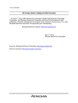
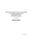
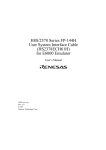
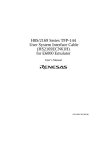
H8S/2214 Series TBP-112 User System Interface Cable (HS2214ECB61H) for E6000 Emulator User’s Manual HS2214ECB61HE(C) Cautions 1. Renesas neither warrants nor grants licenses of any rights of Renesas’s or any third party’s patent, copyright, trademark, or other intellectual property rights for information contained in this document. Renesas bears no responsibility for problems that may arise with third party’s rights, including intellectual property rights, in connection with use of the information contained in this document. 2. Products and product specifications may be subject to change without notice. Confirm that you have received the latest product standards or specifications before final design, purchase or use. 3. Renesas makes every attempt to ensure that its products are of high quality and reliability. However, contact Renesas’s sales office before using the product in an application that demands especially high quality and reliability or where its failure or malfunction may directly threaten human life or cause risk of bodily injury, such as aerospace, aeronautics, nuclear power, combustion control, transportation, traffic, safety equipment or medical equipment for life support. 4. Design your application so that the product is used within the ranges guaranteed by Renesas particularly for maximum rating, operating supply voltage range, heat radiation characteristics, installation conditions and other characteristics. Renesas bears no responsibility for failure or damage when used beyond the guaranteed ranges. Even within the guaranteed ranges, consider normally foreseeable failure rates or failure modes in semiconductor devices and employ systemic measures such as fail-safes, so that the equipment incorporating Renesas product does not cause bodily injury, fire or other consequential damage due to operation of the Renesas product. 5. This product is not designed to be radiation resistant. 6. No one is permitted to reproduce or duplicate, in any form, the whole or part of this document without written approval from Renesas. 7. Contact Renesas’s sales office for any questions regarding this document or Renesas semiconductor products. Preface Thank you for purchasing this user system interface cable (HS2214ECB61H) for the Renesas’s original microcomputer H8S/2214series. The HS2214ECB61H is a user system interface cable that connects an H8S/2214 series E6000 emulator (HS2214EPI61H; hereinafter referred to as the emulator) to the IC socket for a TBP-112 package for the H8S/2214 series MCU on the user system. i Contents Section 1 Configuration....................................................................................1 Section 2 Connection Procedures ......................................................................3 2.1 2.2 2.3 2.4 2.5 Connecting User System Interface Cable to Emulator Station ......................................... 3 Connecting User System Interface Cable to User System ................................................ 5 2.2.1 Soldering the IC Socket ....................................................................................... 5 2.2.2 Inserting Cable Head ........................................................................................... 8 2.2.3 Fastening Cable Head .......................................................................................... 9 2.2.4 Fastening Cable Body.......................................................................................... 11 Recommended Dimensions for User System Mount Pad ................................................. 12 Dimensions for User System Interface Cable Head.......................................................... 13 Resulting Dimensions after Connecting User System Interface Cable ............................. 14 Section 3 Installing the MCU to the User System.............................................15 Section 4 Verifying Operation...........................................................................17 Section 5 Notice ................................................................................................18 ii Section 1 Configuration CAUTION Use an CSPACK112A1110H01 socket (socket (manufactured by Tokyo Eletech Corporation) for the TBP-112 package IC socket on the user system. Figure 1 shows the configuration of the HS2214ECB61H user system interface cable for the TBP-112 package. To emulator station Cable body Screws (M1.6 x 8 mm) (for fastening cable head) Cable head Spacer IC socket Cover User system Figure 1 HS2214ECB61H User System Interface Cable 1 Table 1 lists the HS2214ECB61H components. Please make sure you have all of these components when unpacking. Table 1 HS2214ECB61H Components No. Component Quantity Remarks Includes flat cable 1 Cable body 1 2 Cable head 1 3 IC socket 1 For the TBP-112 package 4 Spacer 1 For installing an TBP-112 packaged MCU 5 Cover 1 For installing an TBP-112 packaged MCU 6 Screws (M1.6 x 8 mm) 4 For fastening cable head and for installing an TBP-112 packaged MCU 7 Driver 1 Dedicated screwdriver to fasten the screws. 8 Documentation 1 User’s manual for HS2214ECB61H (this manual) 2 Section 2 Connection Procedures 2.1 Connecting User System Interface Cable to Emulator Station WARNING Observe the precautions listed below. Failure to do so will result in a FIRE HAZARD and will damage the user system and the emulator product or will result in PERSONAL INJURY. The USER PROGRAM will be LOST. 1. Always switch OFF the user system and the emulator product before the USER SYSTEM INTERFACE CABLE is connected to or removed from any part. Before connecting, make sure that pin 1 on both sides are correctly aligned. 2. The user system interface cable dedicated to the emulator must be used. To connect the cable body to the emulator station, follow the instructions below. 1. Make sure the user system and emulator station are turned off. CAUTION When connecting or removing the user system interface cable, apply force only in the direction suitable for connection or removal, while making sure not to bend or twist the cable or connectors. Otherwise, the connectors will be damaged. 2. After making sure the direction of the cable body connector is correct, firmly insert the cable body connector into the emulator station socket (figure 2). 3 Figure 2 Connecting User System Interface Cable to Emulator Station 4 2.2 Connecting User System Interface Cable to User System WARNING Always switch OFF the user system and the emulator product before the USER SYSTEM INTERFACE CABLE is connected to or removed from any part. Before connecting, make sure that pin 1 on both sides are correctly aligned. Failure to do so will result in a FIRE HAZARD and will damage the user system and the emulator product or will result in PERSONAL INJURY. The USER PROGRAM will be LOST. To connect the cable head to the user system, follow the instructions below. 2.2.1 Soldering the IC Socket Install the socket for TBP-112-packaged ICs on the user system. (1) Gently apply solder to the BGA pads of the user system. Be careful to keep the thickness of the solder within 100 to 150 µm. Too much solder will cause short-circuiting of the pins. (2) The IC socket is vacuum-packed to avoid oxidization of the surfaces of the solder balls. It is thus recommended that the IC socket be installed on the user system if you don’s install the socket immediately after the package it comes in is opened. After the package’s seal has been broken, store the socket in a desiccator. Do not touch the solder balls. If they are touched, solder may not adhere to the solder surface. The IC socket is covered by a protective cover. Socket and cover are fastened together by four screws before the whole is vacuum packed to prevent bending of the IC socket’s pins. To avoid the scattering (dispersal) of flux from other components to the IC socket, keep the protective cover on the IC socket until solder reflow has been completed. (3) Install the provided guide pins into the holes for the guide pins on the user system. Check that the pads are correctly aligned with the IC socket. 5 (4) Notes on soldering the IC socket a) The IC socket is larger than the actual IC package; therefore, refer to figure 7 for the installation of other components. b) Do not install components that occupy large volume close to the IC socket. Such components will prevent the convective flow of heat during reflow. c) Since the IC socket has a greater volume than the IC package, it is recommended that the temperature profile under the conditions used in installation be measured by attaching a temperature sensor to the back side of the IC socket. d) Under the reflow conditions for soldering the IC socket, specify the actual heating to more than 210°C for 30 to 60 seconds. Recommended Reflow Conditions Surface temperature of IC-socket connector Preheating: 150 to 180°C for 180 seconds Actual heating: To more than 210°C, for 30 to 60 seconds 6 CAUTION 1. Never dip the IC socket in flux or use wash to clean the IC socket. This is because flux may remain inside the IC socket due to the IC socket’s structure. When using the IC socket with other DIP products, never clean the other DIP products with flux because the flux may enter the connector through the guide pins of the IC socket. 2. When an IC socket with guide pins is soldered to the user system, about 1.4 mm of the guide pins will stick out (when the user-system board is 1.6 mm thick). When a load is applied to the guide pins from the back of the user-system board, stress will be applied to the soldered part of the IC socket, and this may destroy the connectors. Do not apply any load to the guide pins after the IC socket has been soldered on the user system. 3. When an IC socket with no guide pins is soldered to the user system, the soldered part will crack if stress is applied to the IC socket. Therefore, always apply adhesive to the connector and the user system so that there is a firm connection between them. 4. When the IC socket has guide pins, it is recommended that epoxy resin adhesive or solder be applied to the guide pins at the back of the user system to make sure that no stress is applied to the soldered part 7 2.2.2 Inserting Cable Head CAUTION Check the location of pin 1 before inserting. Align pin 1 on the IC socket for an TBP-112 package on the user system with pin 1 on the user system interface cable head, and insert the user system interface cable head into the IC socket on the user system, as shown in figure 3. Figure 3 Connecting User System Interface Cable to User System 8 2.2.3 Fastening Cable Head CAUTION 1. Use the screwdriver whose head matches the screw head. 2. The tightening torque must be 0.054 N•m or less. If the applied torque cannot be accurately measured, stop tightening when the force required to turn the screw becomes significantly greater than that needed when first tightening. If a screw is tightened too much, the screw head may break or an IC socket contact error may be caused by a crack in the IC socket solder. 3. If the emulator does not operate correctly, cracks might have occurred in the solder. The user system interface cable (HS2214ECB61H) head and the IC socket for the TBP-112 package on the user system have no pin dedicated for alignment. Use the follow procedure to fasten the cable head. 1. Insert two screws (M1.6 x 8 mm) to ① and ③, and screw it a little so that holes at ②-②' and ④-④' match, respectively. 2 ’ 1 ’ 2 1 3 ’ 4 ’ 3 4 Figure 4 Fastening Cable Head Procedure (1) 9 2. Next, fasten screws to ② and ④ a little, so that four screw holes are aligned. Then, each screw should be tightened a little at a time, alternating between screws on opposing corners. 2 4 Figure 5 Fastening Cable Head Procedure (2) 10 2.2.4 Fastening Cable Body Connect the cable body to the cable head. Figure 6 Fastening Cable Body 11 2.3 Recommended Dimensions for User System Mount Pad Figure 7 shows the recommended dimensions for the mount pad (footprint) for the user system with an IC socket for an TBP-112 package (CSPACK112A1110H01: socket (manufactured by Tokyo Eletech Corporation). Note that the dimensions in figure 7 are somewhat different from those of the actual chip's mount pad. Figure 7 Recommended Dimensions for Mount Pad 12 2.4 Dimensions for User System Interface Cable Head The dimensions for the user system interface cable head are shown in figure 8. Figure 8 Dimensions for User System Interface Cable Head 13 2.5 Resulting Dimensions after Connecting User System Interface Cable The resulting dimensions, after connecting the user system interface cable head to the user system, are shown in figure 9. Figure 9 Resulting Dimensions after Connecting User System Interface Cable 14 Section 3 Installing the MCU to the User System CAUTION 1. Check the location of pin 1 before inserting. 2. Use a provided screwdriver. 3. The tightening torque must be 0.054 N•m or less. If the applied torque cannot be accurately measured, stop tightening when the force required to turn the screw becomes significantly greater than that needed when first tightening. If a screw is tightened too much, the screw head may break or an IC socket contact error may be caused by a crack in the IC socket solder. 4. If the MCU does not operate correctly, cracks might have occurred in the solder. 1. Attach the spacer and cover to the IC socket. 2. Place the spacer on the IC socket. Place the two guide pins of the spacer in the corresponding holes on the IC socket. 3. Place the MCU gently in the opening of the spacer. Be sure to correctly align pin 1 of the MCU with the IC socket. The solder balls of the MCU will then be in the correct locations relative to the connection pins of the IC socket. 4. Put the cover on the spacer. The four holes at the four corners of the spacer and of the cover must be aligned. Use the four screws to fasten the cover to the IC socket. Each screw in turn should be made a little tighter, alternating between screws on opposing corners. Use the screwdriver provided with the package. The torque in tightening must be 0.054 N•m or less. 5. When removing the cover from the IC socket, hold the side of the cover so that no stress is applied to the soldered connections between the IC socket and user system while the screws on the cover are being unscrewed. Use tweezers to remove the MCU from the opening in the spacer, 15 Figure 10 Installing MCU to User System 16 Section 4 Verifying Operation 1. When using the E6000 emulator for the H8S/2214 series, turn on the emulator according to the procedures described in the H8S Series E6000 Emulator User's Manual (HS2000EPI61HE). 2. Verify the user system interface cable connections by accessing the external memory and ports to check the bus states of the pins with the MEMORY_FILL command (emulator command). If an error is detected, recheck the soldered IC socket and the location of pin 1. 3. The emulator connected to this user system interface cable supports two kinds of clock sources as the MCU clock: an emulator internal clock and an external clock on the user system. For details, refer to the Emulator Supplementary Information (HS2214EPI61HE). To use the emulator internal clock Select the clock in the emulator station as the system clock (φ), by using the CLOCK command (emulator command). To use the external clock on the user system Supply the external clock from the user system to the emulator. Connect a crystal oscillator to the EXTAL and XTAL terminals for the system clock (φ). Select the external clock as the system clock (φ), by using the CLOCK command (emulator command). For details, refer to section 16, Clock Pulse Generator, in the H8S/2214 Series Hardware Manual. Figure 11 shows the oscillator circuit on the user system interface cable. R1 1 M HCU04 HCU04 To E6000 emulator HCU04 R2 270 EXTAL XTAL Figure 11 Oscillator Circuit 17 Section 5 Notice 1. Make sure that pin 1 on the user system IC socket is correctly aligned with pin 1 on the cable head before inserting the cable head into the user system IC socket. 2. The dimensions of the recommended mount pad for the user system IC socket are different from those of the MCU. 3. This user system interface cable is specifically designed for the HS2214EPI61H emulator. Do not use this cable with any other emulator station. 4. To prevent breaking of wires in the cable body, do not place heavy or sharp metal objects on the user system interface cable. 5. While the emulator station is connected to the user system with the user system interface cable, force must not be applied to the cable head. Place the emulator station, user system interface cable, and user system as shown in the example in figure 12. Figure 12 User System Interface Cable Location Example 6. The P1 short connector is used for testing. Do not remove the short pin that is inserted in the side of pin 1 and pin 2. Figure 13 Short Connector 18