1
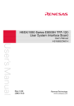
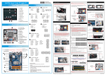
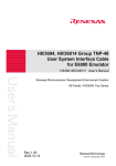
H8S/2168 Group TFP-144
User System Interface Cable
for E6000 Emulator
HS2168ECN61H
User’s Manual
Renesas Microcomputer Development Environment System
H8S Family / H8S/2100 Series
Rev.2.00
2003.12.25
Preface
Thank you for purchasing this user system interface cable (HS2168ECN61H) for the Renesas’
original microcomputer H8S/2168 group.
The HS2168ECN61H is a user system interface cable that connects an H8S/2168 group E6000
emulator (HS2168EPI61H; hereinafter referred to as the emulator) to the IC socket for a TFP-144
package on the user system.
i
Contents
Section 1
Configuration....................................................................................1
Section 2 Connection Procedures ......................................................................3
2.1
2.2
2.3
2.4
2.5
Connecting User System Interface Cable to Emulator Station ......................................... 3
2.1.1 Connecting User System Interface Cable to Cable Body Connector................... 4
2.1.2 Connecting EIO Board 2 to Emulator.................................................................. 5
2.1.3 Removing EIO Board 2 from Emulator............................................................... 6
Connecting User System Interface Cable to User System ................................................ 7
2.2.1 Installing IC Socket ............................................................................................. 7
2.2.2 Soldering IC Socket ............................................................................................. 8
2.2.3 Inserting Cable Head ........................................................................................... 9
2.2.4 Fastening Cable Head .......................................................................................... 9
2.2.5 Fastening Cable Body.......................................................................................... 11
Recommended Dimensions for User System Mount Pad ................................................. 12
Dimensions for User System Interface Cable Head.......................................................... 13
Resulting Dimensions after Connecting User System Interface Cable ............................. 14
Section 3 Installing the MCU on the User System............................................15
Section 4 User System Interface Circuit ...........................................................17
Section 5 Verifying Operation...........................................................................19
Section 6 Notice ................................................................................................20
ii
Section 1
Configuration
CAUTION
Use an NQPACK144SE socket (manufactured by
Tokyo Eletech Corporation) for the TFP-144 package IC
socket on the user system.
Figure 1 shows the configuration of the HS2168ECN61H user system interface cable for the
TFP-144 package.
To emulator station
Screws (M2.6 x 6 mm)
CTS screws (M3 x 6 mm)
for fastening the emulator station
Cable body
EIO board 2
EIO board 1
Screws (M2.0 x 10 mm)
(for fastening cable head)
Screws (M2.0 x 6 mm)
Socket cover
Cable head
IC socket
User system
Figure 1 HS2168ECN61H User System Interface Cable
1
Table 1 lists the HS2168ECN61H components. Please make sure you have all of these components
when unpacking.
Table 1
HS2168ECN61H Components
No. Component
Quantity
Remarks
Includes coaxial cable and two EIO boards
1
Cable body
1
2
Cable head
1
3
IC socket
1
For the TFP-144 package
4
Socket cover
1
For installing a TFP-144 packaged MCU
5
Screws (M2.6 x 6 mm)
2
For fastening EIO board 2
6
Screws (M2.0 x 10 mm)
4
For fastening cable head
7
Screws (M2.0 x 6 mm)
4
For installing a TFP-144 packaged MCU
8
CTS screws (M3 x 6 mm)
2
For fastening the emulator station
9
Guide pins (φ 1 mm)
3
For determining the IC socket location
10
Screwdriver
1
For tightening screws
11
Documentation
1
User’s manual for HS2168ECN61H (this manual)
2
Section 2 Connection Procedures
2.1
Connecting User System Interface Cable to Emulator Station
WARNING
Observe the precautions listed below. Failure to do so
will result in a FIRE HAZARD and will damage the user
system and the emulator product or will result in
PERSONAL INJURY. The USER PROGRAM will be
LOST.
1. Always switch OFF the user system and the emulator
product before the USER SYSTEM INTERFACE CABLE
is connected to or removed from any part. Before
connecting, make sure that pin 1 on both sides are
correctly aligned.
2. The user system interface cable dedicated to the
emulator must be used.
Make sure the user system and the emulator station are turned off.
CAUTION
When connecting or removing the user system interface
cable, apply force only in the direction suitable for
connection or removal, while making sure not to bend or
twist the cable or connectors. Otherwise, the connectors
will be damaged.
3
2.1.1
Connecting User System Interface Cable to Cable Body Connector
After making sure the direction of the cable body connector is correct, firmly insert the cable body
connector into the emulator station socket, and fasten the emulator station with two CTS screws
(M3 × 6 mm) (figure 2).
E
0
0
0
6
Emulator station
Cable body connector
CTS screws (M3 x 6 mm)
User system interface cable
Figure 2 Connecting User System Interface Cable to Emulator Station (1)
4
2.1.2
6.
Remove four screws at the side of the emulator station.
Pull up and remove the cover of the emulator casing.
Insert connector P5 of EIO board 2 into connector P5 in the emulator station.
Fasten EIO board 2 with the provided two screws (M2.6 × 6 mm).
Set up the coaxial cable, which has been connected to EIO board 2, into a gutter of the emulator
station.
Set the cover of the emulator station and fasten four screws.
E6000
1.
2.
3.
4.
5.
Connecting EIO Board 2 to Emulator
EIO board 2
connector P5
of EIO board 2
connector P5 of
emulator station
Figure 3 Connecting User System Interface Cable to Emulator Station (2)
5
2.1.3
1.
2.
3.
4.
5.
6.
6
Removing EIO Board 2 from Emulator
Remove four screws from the side of the emulator station.
Pull up and remove the cover of the emulator casing.
Remove two screws (M2.6 × 6 mm) from EIO board 2.
Remove EIO board 2 from connector P5 of the emulator station.
Remove the coaxial cable, which has been connected to EIO board 2, from a gutter of the
emulator station.
Set the cover of the emulator station and fasten four screws.
2.2
Connecting User System Interface Cable to User System
WARNING
Always switch OFF the user system and the emulator
product before the USER SYSTEM INTERFACE CABLE
is connected to or removed from any part. Before
connecting, make sure that pin 1 on both sides are correctly
aligned. Failure to do so will result in a FIRE HAZARD and
will damage the user system and the emulator product or
will result in PERSONAL INJURY. The USER PROGRAM will
be LOST.
To connect the cable head to the user system, follow the instructions below.
2.2.1
Installing IC Socket
After checking the location of pin 1 on the IC socket fasten it to the user system before soldering.
CAUTION
After confirming the location of pin 1 on the IC socket,
apply epoxy resin adhesive to the end of the four projections
at the bottom of the IC socket, and fasten it to the user
system.
7
Use the guide pins provided to determine where to install the IC socket, as shown in figure 4.
Pin 1
Guide pins
4 projections to apply
epoxy resin adhesive to
Bottom view of IC socket
IC socket
(NQPACK144SE
manufactured by
Tokyo Eletech Corporation)
User system
Figure 4 Location Setting of IC Socket
2.2.2
Soldering IC Socket
After fastening, solder the IC socket for a TFP-144 package to the user system.
CAUTION
Be sure to completely solder the leads so that the solder
slops gently over the leads and forms solder fillets. (Use
slightly more solder than the MCU.)
8
2.2.3
Inserting Cable Head
CAUTION
Check the location of pin 1 before inserting.
Align pin 1 on the IC socket for a TFP-144 package on the user system with pin 1 on the user system
interface cable head, and insert the user system interface cable head into the IC socket on the user
system, as shown in figure 5.
2.2.4
Fastening Cable Head
CAUTION
1. Use a screwdriver whose head matches the screw head.
2. The tightening torque must be 0.054 N•m or less.
If the applied torque cannot be accurately measured,
stop tightening when the force required to turn the screw
becomes significantly greater than that needed when first
tightening. If a screw is tightened too much, the screw
head may break or an IC socket contact error may be
caused by a crack in the IC socket solder.
3. If the emulator does not operate correctly, cracks might
have occurred in the solder. Check conduction with
a tester and re-solder the IC socket if necessary.
9
Fasten the user system interface cable head to the IC socket for a TFP-144 package on the user
system with the four screws (M2.0 × 10 mm) provided. Each screw should be tightened a little at a
time, alternating between screws on opposing corners. Take special care, such as manually securing
the IC socket soldered area, to prevent the soldered IC socket from being damaged by
overtightening the screws or twisting the components.
Screws (M2.0 x 10 mm)
Pin 1
Cable head
IC socket
(NQPACK144SE
manufactured by
Tokyo Eletech Corporation)
Pin 1
User system
Figure 5 Connecting User System Interface Cable to User System
10
2.2.5
Fastening Cable Body
Connect the cable body and EIO board 1 to the cable head.
Removing
Cable body
Push the lower part
of EIO board 1 with
your fingers
EIO board 1
Cable body
Remove jig
EIO board 1
Cable head
User system
Figure 6 Fastening Cable Body and EIO Board 1
When removing the cable body or EIO board 1, push the unfastening jigs.
If the lower part of the cable body is pushed, EIO board 1 may be removed. Push the lower part of
EIO board 1 with your fingers.
11
2.3
Recommended Dimensions for User System Mount Pad
Figure 7 shows the recommended dimensions for the mount pad (footprint) for the user system with
an IC socket for a TFP-144 package (NQPACK144SE: manufactured by Tokyo Eletech
Corporation). Note that the dimensions in figure 7 are somewhat different from those of the actual
chip's mount pad.
0.40 X 35 = 14.00 ± 0.05
3.0 - Ø1.0
8.0
15.10 MAX
19.10 min
8.0
Unit: mm
Figure 7 Recommended Dimensions for Mount Pad
12
0.40 X 35 = 14.00 ± 0.05
0.2 ± 0.05
0.40 ± 0.05
0.40 ± 0.05
2.4
Dimensions for User System Interface Cable Head
76.2
25.0
The dimensions for the user system interface cable head are shown in figure 8.
25.6
25.0
20.5
66.0
Unit: mm
Tolerance: ±0.5 mm
Figure 8 Dimensions for User System Interface Cable Head
13
2.5
Resulting Dimensions after Connecting User System Interface Cable
13.3
48.3
The resulting dimensions, after connecting the user system interface cable head to the user system,
are shown in figure 9.
Cable head
User system
IC socket
(NQPACK144SE
manufactured by
Tokyo Eletech Corporation)
Unit: mm
Tolerance: ±0.5 mm
Figure 9 Resulting Dimensions after Connecting User System Interface Cable
14
Section 3 Installing the MCU on the User System
CAUTION
1. Check the location of pin 1 before inserting.
2. Use a screwdriver whose head matches the screw head.
3. The tightening torque must be 0.054 N•m or less.
If the applied torque cannot be accurately measured,
stop tightening when the force required to turn the screw
becomes significantly greater than that needed when first
tightening. If a screw is tightened too much, the screw
head may break or an IC socket contact error may be
caused by a crack in the IC socket solder.
4. If the MCU does not operate correctly, cracks might have
occurred in the solder. Check conduction with a tester
and re-solder the IC socket if necessary.
Check the location of pin 1 before inserting the MCU into the IC socket on the user system, as
shown in figure 10. After inserting the MCU, fasten the socket cover with the provided four screws
(M2.0 × 6 mm). Take special care, such as manually securing the IC socket soldered area, to prevent
the IC socket from being damaged by overtightening the screws or twisting the components.
15
Screws (M2.0 x 6 mm)
Socket cover
MCU
Pin 1
IC socket
(NQPACK144SE
manufactured by
Tokyo Eletech Corporation)
User system
Figure 10 Installing MCU to User System
16
Section 4 User System Interface Circuit
The microcomputer (H8S/2168) is installed in this user system interface cable for emulating the
LPC function. An interface circuit, as shown in figure 11, is provided for the user system interface
signal of the H8S/2168. Figure 12 and table 2 show the settings of switches.
EIO board 1 (HS2168EIO61H)
H8S/2168
LAD0, LAD1,
LAD2, LAD3,
LFRAME_N,
LRESET_N,
LCLK, SERIRQ
330 Ω
N6
47 kΩ
SW1 to 8
330 Ω
N7
47 kΩ
LSCI, LSMI_N,
PME_N, GA20,
CLKRUN_N,
LPCPD_N
SW9 to 14
HS2168EPI61H
PE0/LAD0
PE1/LAD1
PE2/LAD2
PE3/LAD3
PE4/LFRAME_N
PE5/LRESET_N
PE6/LCLK
PE7/SERIRQ
PD0/LSCI
PD1/LSMI_N
PD2/PME_N
PD3/GA20
PD4/CLKRUN_N
PD5/LPCPD_N
PE0 to 7
PD0 to 5
Figure 11 User System Interface Circuit
Pin 3 side
Pin 1 side
Figure 12 Settings of Switch
17
Table 2 Settings of Switches
Switch Number
Pin 1 Side
Pin 3 Side
SW1
Port E7
SERIRQ
SW2
Port E6
LCLK
SW3
Port E5
LRESET_N
SW4
Port E4
LFRAME_N
SW5
Port E3
LAD3
SW6
Port E2
LAD2
SW7
Port E1
LAD1
SW8
Port E0
LAD0
SW9
Port D5
LPCPD_N
SW10
Port D4
CLKRUN_N
SW11
Port D3
GA20
SW12
Port D2
PME_N
SW13
Port D1
LSMI_N
SW14
Port D0
LSCI
18
Section 5 Verifying Operation
1. When using the E6000 emulator for the H8S/2168 group, turn on the emulator according to the
procedures described in the H8S/2168 Group E6000 Emulator User's Manual
(HS2168EPI61HE).
2. Verify the user system interface cable connections by accessing the external memory and ports
to check the bus states of the pins with the MEMORY_FILL command (emulator command). If
an error is detected, recheck the soldered IC socket and the location of pin 1.
3. The emulator connected to this user system interface cable supports two kinds of clock sources
as the MCU clock: an emulator internal clock and an external clock on the user system. For
details, refer to the emulator user’s manual (HS2168EPI61HE).
⎯ To use the emulator internal clock
Select the clock in the emulator station as the system clock (φ), by using the CLOCK
command (emulator command).
⎯ To use the external clock on the user system
Select the target clock by using the CLOCK command (emulator command) and supply the
external clock from the user system to the emulator. When a crystal oscillator to the EXTAL
and XTAL terminals for the system clock (φ) the crystal oscillator will oscillate in the circuit
as shown in figure 13. External clock must be input from the EXTAL terminal. The clock
input conditions are same as those for the H8S/2168 group in the hardware manual.
HCU04
R1 1 M Ω
HCU04
To E6000 emulator
HCU04
EXTAL
R2 270 Ω
XTAL
Figure 13 Oscillator Circuit
19
Section 6 Notice
1. Make sure that pin 1 on the user system IC socket is correctly aligned with pin 1 on the cable
head before inserting the cable head into the user system IC socket.
2. The dimensions of the recommended mount pad for the user system IC socket are different from
those of the MCU.
3. To avoid breaking wires in the cable body, do not place heavy or sharp metal objects on the user
system interface cable.
4. While the emulator station is connected to the user system with the user system interface cable,
force must not be applied to the cable head. Position the emulator station, user system interface
cable, and user system as shown in figure 14.
Emulator station
Place components so that the cable body
and cable head are parallel to the user system.
Cable
Cable head is parallel
to emulator station
Cable head is parallel
to user system
User system
Figure 14 User System Interface Cable Location Example
5. The P1 short connector is for testing. Do not remove the jumper pin inserted in the side of pin 1
and pin 2.
1
3
P1
Figure 15 P1 Short Connector
20
6. To prevent EMI noise, enclose the user system interface cable head in a case. The recommended
material of the case is iron plated with nickel or resin plated with nickel inside. The case must be
large enough to include the user system interface cable head, user system interface cable, and
target system.
21
Cautions
Keep safety first in your circuit designs!
1. Renesas Technology Corporation puts the maximum effort into making semiconductor
products better and more reliable, but there is always the possibility that trouble may occur
with them. Trouble with semiconductors may lead to personal injury, fire or property damage.
Remember to give due consideration to safety when making your circuit designs, with
appropriate measures such as (i) placement of substitutive, auxiliary circuits, (ii) use of
nonflammable material or (iii) prevention against any malfunction or mishap.
Notes regarding these materials
1. These materials are intended as a reference to assist our customers in the selection of the
Renesas Technology Corporation product best suited to the customer's application; they do not
convey any license under any intellectual property rights, or any other rights, belonging to
Renesas Technology Corporation or a third party.
2. Renesas Technology Corporation assumes no responsibility for any damage, or infringement
of any third-party's rights, originating in the use of any product data, diagrams, charts,
programs, algorithms, or circuit application examples contained in these materials.
3. All information contained in these materials, including product data, diagrams, charts,
programs and algorithms represents information on products at the time of publication of these
materials, and are subject to change by Renesas Technology Corporation without notice due to
product improvements or other reasons. It is therefore recommended that customers contact
Renesas Technology Corporation or an authorized Renesas Technology Corporation product
distributor for the latest product information before purchasing a product listed herein.
The information described here may contain technical inaccuracies or typographical errors.
Renesas Technology Corporation assumes no responsibility for any damage, liability, or other
loss rising from these inaccuracies or errors.
Please also pay attention to information published by Renesas Technology Corporation by
various means, including the Renesas Technology Corporation Semiconductor home page
(http://www.renesas.com).
4. When using any or all of the information contained in these materials, including product data,
diagrams, charts, programs, and algorithms, please be sure to evaluate all information as a total
system before making a final decision on the applicability of the information and products.
Renesas Technology Corporation assumes no responsibility for any damage, liability or other
loss resulting from the information contained herein.
5. Renesas Technology Corporation semiconductors are not designed or manufactured for use in
a device or system that is used under circumstances in which human life is potentially at stake.
Please contact Renesas Technology Corporation or an authorized Renesas Technology
Corporation product distributor when considering the use of a product contained herein for any
specific purposes, such as apparatus or systems for transportation, vehicular, medical,
aerospace, nuclear, or undersea repeater use.
6. The prior written approval of Renesas Technology Corporation is necessary to reprint or
reproduce in whole or in part these materials.
7. If these products or technologies are subject to the Japanese export control restrictions, they
must be exported under a license from the Japanese government and cannot be imported into a
country other than the approved destination.
Any diversion or reexport contrary to the export control laws and regulations of Japan and/or
the country of destination is prohibited.
8. Please contact Renesas Technology Corporation for further details on these materials or the
products contained therein.
H8S/2168 Group TFP-144
User System Interface Cable
for E6000 Emulator User's Manual
Publication Date: Rev.1.00, August 25, 2003
Rev.2.00, December 25, 2003
Published by:
Sales Strategic Planning Div.
Renesas Technology Corp.
Edited by:
Technical Documentation & Information Department
Renesas Kodaira Semiconductor Co., Ltd.
©2003 Renesas Technology Corp. All rights reserved. Printed in Japan.
H8S/2168 Group TFP-144
User System Interface Cable
for E6000 Emulator
User’s Manual
REJ11Jxxxx-xxxxx