1
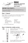
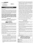
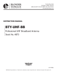
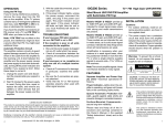
Paso 54Acoplar el Cable de Conectores a la Antena
Le recomendamos utilizar el cable RG-6 y, si prepara su propio cable, un conector F de calidad. Aviso: Si prepara su propio cable, deslice un recubrimiento aislante de transformador análogo en el cable antes de fijar el conector F.
1. Enrosque los extremos del terminal de la batería de un transformador
análogo a través de cualquiera de las lengüetas de alivio de tensión de
la antena. Luego utilice las arandelas y las tuercas de mariposa grandes
suministradas para asegurar los conectores del transformador a los terminales enroscados de los conectores rotulados CONNECT LEAD-IN
HERE (Acoplar conector aquí).
2. Enrosque el conector F del cable en el transformador análogo. Si utiliza
un cable preconstruido sin un recubrimiento aislante, cubra la conexión
con una cinta autoadhesiva impermeable. De lo contrario, deslice el recubrimiento aislante sobre la conexión.
INSTRUCCIONES DE INSTALACIÓN
ANT3020X
ANT3036W
ANT3036X
Extremos del Terminal
de la Batería
Lengueta Plástica de
Alivio de Tensión
Terminales de
Conectores
Conector F
Recubrimiento Aisante
Cable Coaxial
Paso 24Ensamblar la Abrazadera del Mástil
PRECAUCIÓN
ADVERTENCIA: LA INSTALACIÓN DE ESTE PRODUCTO
PUEDE RESULTAR PELIGROSA. POR SU SEGURIDAD,
OBSERVE LAS INSTRUCCIONES DE INSTALACION.
1. Utilice el herraje suministrado para fijar sin apretar el conjunto de la
abrazadera del mástil, incluido, al brazo principal de la antena, Para
los modelos ANT3036X y ANT3036W, fije el conjunto de la abrazadera del mástil del brazo de soporte, orientado en la misma dirección que el conjunto de la abrazadera del mástil del brazo principal.
Perno en U Abrazadera del Mástil
Antes de Comenzar
Lea este manual y la información provista por la Comisión para la
Seguridad de los Productos de Consumo. Por su seguridad y conveniencia, planifique cada paso de la instalación y compre el herraje
necesario con anticipación. El herraje necesario y el orden en que
deberá realizar los pasos dependerán de los métodos de conexión y
montage que utilizará.
Brazo Principal
Placa de Respaldo
2. Presione los tapones de extremo grandes suministrados en los extremos
del brazo principal de la antena ya el brazo de soporte de los modelos
ANT3036X y ANT3036W.
Paso 34Ensamblar el Brazo de Soporte
4ENSAMBLAJE DE LA ANTENA
Para instalación en exteriores, le recomendamos ensamblar la antena en
su totalidad en el piso, y luego montarla en un mástil. Para instalación en
áticos, primero mida su ático para asegurarse de poder acomodar la antena
ensamblada por la puerta. Si no puede acomodar la antena ensamblada por
la pueta, deberá llevar a cabo la maor parte del ensamblaje en el ático.
1. Para los models ANT3036X y ANT3036W, alinee las correas del brazo
de soporte y la abrazadera del mástil con los orificios de las correas de
soporte del brazo principal y la abrazadera del mástil.
2. Fije las correas de soporte al brazo principal mediante los tornillos de 1½
pulg. y las tuercas de mariposa grandes suministrados.
Brazo Principal
Consulte la caja y la etiqueta para conocer cuál es el modelo de antena que
adquirió. Los pasos a continuación aplican a todos los modelos o, donde se
especifique, aplican únicamente a los modelos ANT3036X y ANT3036W.
Paso 14Asegurar las Secciones del Brazo Principal
Para los modelos ANT3036X y ANT3036W, utilice el herraje suministrado
para ensamblar las secciones del brazo principal. De ser necesario, eleve un
extremo del brazo principal de manera que los cables entrecruzados puedan
alcanzar los postes roscados de la siguiente sección. Aviso: En la sección
posterior no hay cables entrecruzados.
Cables
Tuercas de
Mariposa Grandes Entrecruzados
Tornillos
de 1½ pulg.
Arandelas
Planas
Postes
Roscados
Varilla
►Su antena puede
ser diferente a la
que se ilustra aquí.
Contratuercas
Tuercas de
Mariposa Grandes
►Su antena puede
ser diferente a la
que se ilustra aquí.
1. Sujete los brazos d mariposa de UHF y gire sus elementos hasta que encajen en su posición (de manera perpendicular a los brazos de mariposa).
2. Presione los tapones de extremo pequeños suministrados en los extremos
de los brazos de mariposa.
3. Pliegue los brazos de mariposa y asegúrelos en su posición mediante los
dos tornillos de 1¼ pulg. y las tuercas de mariposa suministrados.
4. Sostenga los elementos del brazo hasta que enganchen en los soportes de
fijación.
Aviso: Espere a instalar la antena en el techo o el ático para desdoblar los elementos. Precaución: No tire de los elementos por los extremos exteriores
para evitar ocasionarles daño.
Elementos del Brazo
de Mariposa
Brazo de Mariposa
Tornillos de 1¼ pulg.
Tuercas de Mariposa Penqueñas
Le recomendamos obtener la ayuda de otra persona antes de instalar el
mástil o de montar su antena al mástil. La manera en que configure su mástil
dependerá de su instalación especifica. Consulte la información provista por
la Comisón para la Seguridad de los Productos de Consumo sobre los métodos recomendados.
1. Con los soportes de fijación de la antena en la parte superior del brazo,
deslice el conjunto de la abrazadera del mástil de la antena (o conjuntos para los modelos ANT3036X y ANT3036W) por encima del mástil.
Para los modelos ANT3036X y ANT3036W, asegúrese que el brazo
principal se encuentre en la parte superior con los soportes plásticos en
la parte superior, y el brazo de soporte por debajo.
2. Apriete las contratuercas del conjunto de la abrazadera del mástil para
sujetar la antena en su posición. No apriete demasiado las contratuercas.
Precaución: Los cables entrecruzados no deberán entrar en contacto con el
brazo de la antena, el mástil, o entre si. De ser necesario, doble con cuidado
los cables entrecruzados para brindar un espacio libre de al menos 1,27 cm.
Abrazadera del Mástil
Soporte de Sujeción
Cabled Entrecruzados
Brazo de Soporte
Brazo Principal
Mástil
►Su antena puede
ser diferente a la
que se ilustra aquí.
3. Configure el mástil, luego gírelo de manera que los elementos más cortos de la antena queden orientados hacia las emisoras que desee recibir.
Entonces, asegure el mástil en su posición.
Aviso: Usted puede además colocar la antena en el ático. Puede montarla desde
un cabio o sencillamente colocarla en el piso del ático. No obstante, le recomendamos utilizar herraje de montaje para la lograr una instalación sólida.
Paso 84Enrutar el Cable a su TV/Receptor de FM
4 Utilice cinta plástica para asegurar el cable coaxial al mástil en intervalos
de 0,91 metros.
4 Utilice abrazaderas con clavo para coaxial a unos cuantos metros entre
si para asegurar el cable entre el mástil y donde el cable entrará a la casa.
4 Utilice un bloque de puesta a tierra de 75 Ohmios en el punto donde el
cable coaxial entrara a la casa. Lea la informacion provista por la comision para la seguridad de los Productos de Consumo sobre las instrucciones de puesta a tierra.
4 Utilice un lazo de goteo antes de que el cable entre a la casa.
4 Utilice un tubo "Wall-thru" para enrutar nítidamente el cable coaxial a
través de las paredes.
4 Utilice únicamente la lonitud del cable coaxial que requiere su instalación. No enrolle cable adicional detrás del receptor. En vez, córtelo a
la longitud correcta.
4GARANTÍA LIMITADA DE 12 MESES
Brazo
de Soporte
Paso 44Ensamblar la Red de Aislamiento y Dipolo UHF
1. Para los modelos ANT3036X y ANT3036W, separe las dos mitades del
dipolo UHF del brazo principal hasta que queden afianzados en el soporte de fijación.
2. Coloque el extremo no afianzado de las mitades sobre uno de los terminales de los conectores de la antena (uno para cada mitad del bucle UHF
en cada lado del brazo). Aviso: Ambas barras de la red de aislamiento
deben permanecer paralelas al brazo principal.
Dipolo UHF
Paso 64Desdoblar los Elementos de la Antena
Brazo de Mariposa
Correas de Soporte
►Su antena puede
ser diferente a la
que se ilustra aquí.
Transformador
Análogo
Arandelas Planas
Tuercas de Mariposa
►Su antena puede
ser diferente a la
que se ilustra aquí.
Paso 74Acoplar la Antena al Mástil
Red de Aislamiento
Brazo Principal
Terminal de Conectores
Audiovox Electronics Corporation (la “Compañia”) le garantiza a usted, el comprador original de este producto que si, bajo condiciones y uso normales, se encontrara que este producto o alguna pieza presenta
defectos materiales o de mano de obra dentro de los primeros 12 messes a partir de la fecha de compra original, tales defectos serán reparados o reemplazados (a opción de la Compañia) sin cargo alguno por las
piezas y labores de reparación. Para obtener los servicios de reparación o reemplazo dentro de los términos de esta Garantia, el producto junto con cualquier accesorio incluido en el empaque original se entregarán
con prueba de garantia. No devuelva este producto al Distribuidor.
Esta Garantía no es transferible y no cubre un producto adquirido, mantenido o utilizado fuera de los Estados Unidos o Canadá. Esta garantía no incluye la eliminación de estática o ruido generados externamente.
Esta garantía no incluye los costos incurridos en la instalación remoción o reinstalación de este producto, o, si es opinión de la Compañia, que este producto ha sufrido daños debido a causas de fuerza mayor,
alteraciones, instalación inadecuada, abuso, uso indebido, negligencia o accidente. Esta garantia no incluye daños ocasionados por un adapador de CA que no haya sido suministrado con el producto.
EL ALCANCE DE LA RESPONSABILIDAD DE LA COMPAÑIA BAJO ESTA GARANTÍA ESTÁ LIMITADO A LA REPARACIÓN O EL REEMPLAZO PROVISTO ARRIBA Y, EN NINGÚN CASO,
DEBERÁ LA RESPONSABILIDAD DE LA COMPAÑIA EXCEDER EL PRECIO DE COMPRA PAGADO POR EL COMPRADOR DE ESTE PRODUCTO.
Esta Garantía reemplaza cualesquiera otras responsabilidades o garantías expresas. CUALESQUIERA GARANTÍAS IMPLÍCITAS, INCLUYENDO CUALQUIER GARANTÍA IMPLÍCITA DE COMERCIABILIDAD O ADAPTABILIDAD PARA UN PROPÓSITO EN PARTICULAR ESTARÁN LIMITADAS A LA DURACIÓN DE ESTA GARANTÍA. CUALQUIER ACCIÓN PARA EL INCUMPLIMIENTO DE
CUALQUIER GARANTÍA EN EL PRESENTE, INCLUYENDO CUALQUIER GARANTÍA IMPLÍCITA, DEBERÁ PRESENTARSE DENTRO DE UN PERÍODO DE 24 MESES A PARTIR DE LA FECHA
DE COMPRA ORIGINAL. EN NINGÚN CASO LA COMPAÑÍA SERÁ RESPONSABLE POR DAÑOS EMERGENTES O INCIDENTALES. Ninguna persona ni representante está autorizado a asumir, a
nombre de la Compañía, ninguna responsabilidad salvo la expresada aquí en conexión con la venta de este producto.
Algunos estados/provincias no permiten limitaciones sobre la duración de una garantía implícita o la exclusión o la limitación de daños incidentales o emergentes, de modo que es posible que las limitaciones o
exclusiones anteriores no se apliquen en su caso. Esta Garantía le confiere derechos legales específicos; según el estado/provincia, puede disfrutar además de otros derechos.
EE.UU: Audiovox Electronics Corporation, 150 Marcus Blvd., Hauppauge, New York 11788
CANADÁ: Audiovox Return Center, c/o Genco, 6685 Kennedy Road, Unit #3 Door 16, Mississauga Ontario L5T 3A5
©2007 AEC, 150 Marcus Blvd. Hauppauge, NY 11788
Step 54Connecting Lead-in Cable To The Antenna
We recommend RG-6 cable, and, if you prepare your own cable, a quality
F-connector. Note: If you prepare your own cable, slide a matching transformer’s weatherboot onto the cable before you attach the F-connector.
1. Thread the spade terminal ends of a matching transformer through either slot on the antenna’s strain relief tab. Then use the supplied washers and large wing nuts to secure the transformer’s leads to the antenna’s threaded lead-in terminals marked CONNECT LEAD-IN HERE.
2. Screw the cable’s F-connector onto the matching transformer. If you
use a prebuilt cable without a weatherboot, cover the connection with
weatherproof tape. Otherwise, slip the weatherboot over the connection.
INSTALLATION DIRECTIONS
ANT3020X
ANT3036W
ANT3036X
Step 74Attaching The Antenna To The Mast
We recommend you get the help of another person before you put up the
mast or attach your antenna to it. How you set up your mast depends on
your specific installation. Refer to the Consumer Product Safety Commission information for recommended methods.
1. With the antenna’s support brackets on top of the boom, slide the antenna’s mast clamp assembly (or assemblies for models ANT3036X
and ANT3036W) over the top of the mast. For models ANT3036X
and ANT3036W make sure the main boom is on top with the plastic
brackets on top, and the support boom is underneath.
2. Tighten the mast clamp assembly’s lock nuts to hold the antenna in place.
Do not overtighten the lock nuts.
Caution: The crossover wires must not touch the antenna boom, the mast,
or each other. If necessary, carefully bend the crossover wires to provide at
least 1/2 inch of clearance.
Mast Clamp
Support Bracket
Support Boom
CAUTION
WARNING: INSTALLATION OF THIS PRODUCT IS
DANGEROUS. FOR YOUR SAFETY, FOLLOW THE
INSTALLATION DIRECTIONS.
Main Boom
Step 24Mast Clamp Assembly
1. Use the supplied hardware to loosely attach the supplied mast clamp
assembly to the main antenna boom. For models ANT3036X and
ANT3036W, attach the support boom’s mast clamp assembly, facing it
the same direction as the main boom’s mast clamp assembly.
Before You Begin
Read this manual and the Consumer Product Safety Commission information. For your safety and convenience, plan each
step of the installation and purchase the necessary hardware in
advance. The hardware required and the order in which you
perform the steps depends on the mounting and connection
methods you choose.
4ASSEMBLING THE ANTENNA
For outdoor installation, we recommend you assemble the entire antenna
on the ground, then mount it on a mast. For attic installation, first measure your attic to make sure the assembled antenna will fit. The assembled
antenna might not fit through your attic’s entrance, so you might need to
perform most of the assembly in the attic.
Look at the carton and label to see what model of antenna you have. The
steps below apply to all models or, where specified, apply only to models
ANT3036X and ANT3036W.
Step 14Splinting the Main Boom Sections Together
For models ANT3036X and ANT3036W, use the supplied hardware to
assemble the main boom sections. If necessary, lift one end of the main
boom so the crossover wires reach the threaded posts of the next section.
Note: There are no crossover wires over the back section.
1. Hold each UHF wing boom and turn its elements until they snap
squarely into place (perpendicular to the wing booms).
2. Press the supplied small end plugs into the ends of the wing booms.
3. Fold out the wing booms and secure them into position using the two
supplied 1¼-inch screws and wing nuts.
4. Hold the main boom’s elements near the pivot points and pull them
away from the boom until they snap into the locking support brackets.
Note: You may wait to unfold the elements until you get the antenna up on
the roof or in your attic. Caution: Do not pull the elements near their outer
ends or you could damage them.
2. Press the supplied large end plugs into the ends of the main antenna
boom and the model ANT3036X and ANT3036W support boom.
Step 34Support Boom Assembly
1. For models ANT3036X and ANT3036W, align the support boom’s straps
and mast clamp with the main boom’s support strap holes and mast clamp.
2. Attach the support straps to the main boom using the two supplied 1½inch screws and large wing nuts.
►Your antenna
may look different
than the one
shown here.
3. Set up the mast, then rotate it so the antenna’s shortest elements point
toward the stations you want to receive. Then secure the mast into position.
Note: You can also put the antenna in an attic space. You can mount it from
a rafter or simply place the antenna on the attic floor. However, we recommend that you use mounting hardware for the most secure installation.
Step 84Routing The Cable To Your TV/FM Receiver
4 Use plastic tape to secure the coaxial cable to the mast at 3-foot intervals.
4 Use coaxial nail clips every few feet to secure the cable between the
mast and where the cable enters the house.
4 Use a 75-ohm grounding block at the point where the coaxial cable
enters the house. Read the Consumer Product Safety Commission information for grounding instructions.
4 Use a drip-loop before the cable enters the house.
4 Use a wall-thru tube to neatly route the coaxial cable thru the walls.
4 Use only the length of coaxial cable that your installation needs. Do not
coil extra cable behind receiver. Instead, cut it to the correct length.
412 MONTH LIMITED WARRANTY
Audiovox Electronics Corporation (the “Company”) warrants to the original retail purchaser of this product that should this product or any part thereof, under normal use and conditions, be proven defective
in material or workmanship within 12 months from the date of original purchase, such defect(s) will be repaired or replaced (at the Company’s option) without charge for parts and repair labor. To obtain
repair or replacement within the terms of this Warranty, the product along with any accessories included in the original packaging is to be delivered with proof of warranty coverage (e.g. dated bill of sale),
specification of defect(s), transportation prepaid, to the Company at the address shown below. Do not return this product to the Retailer.
Step 44UHF Dipole and Isolation Network Assembly
1. For models ANT3036X and ANT3036W, pull the two halves of the
UHF dipole away from the main boom until they lock into the support
bracket.
2. Place each half’s unattached end over one of the antenna’s lead-in terminals (one for each half of the UHF bowtie on each side of the boom).
Note: Both bars of the isolation network should remain parallel to the
main boom.
►Your antenna
may look different
than the one
shown here.
Step 64Unfolding The Antenna Elements
►Your antenna
may look different
than the one
shown here.
►Your antenna
may look different
than the one
shown here.
This Warranty is not transferable and does not cover product purchased, serviced or used outside the United States or Canada. The warranty does not extend to the elimination of externally generated static or
noise. This Warranty does not apply to costs incurred for installation, removal or reinstallation of the product, or, if in the Company’s opinion, the product has been damaged through acts of nature, alteration,
improper installation, mishandling, misuse, neglect, or accident. This warranty does not cover damage caused by an AC adapter not provided with the product.
THE EXTENT OF THE COMPANY’S LIABILITY UNDER THIS WARRANTY IS LIMITED TO THE REPAIR OR REPLACEMENT PROVIDED ABOVE AND, IN NO EVENT, SHALL THE
COMPANY’S LIABILITY EXCEED THE PURCHASE PRICE PAID BY PURCHASER FOR THE PRODUCT.
This Warranty is in lieu of all other express warranties or liabilities. ANY IMPLIED WARRANTIES, INCLUDING ANY IMPLIED WARRANTY OF MERCHANTABILITY OR FITNESS FOR A PARTICULAR PURPOSE, SHALL BE LIMITED TO DURATION OF THIS WARRANTY. ANY ACTION FOR BREACH OF ANY WARRANTY HEREUNDER, INCLUDING ANY IMPLIED WARRANTY, MUST BE BROUGHT WITHIN A PERIOD OF 24 MONTHS FROM THE DATE OF ORIGINAL PURCHASE. IN NO CASE SHALL THE COMPANY BE LIABLE FOR ANY CONSEQUENTIAL
OR INCIDENTAL DAMAGES WHATSOEVER. No person or representative is authorized to assume for the Company any liability other than expressed herein in connection with the sale of this product.
Some states/provinces do not allow limitations on how long an implied warranty lasts or the exclusion or limitation of incidental or consequential damage so the above limitations or exclusions may not apply
to you. This Warranty gives you specific legal rights and you may also have other rights which vary from state/province to state/province.
U.S.A.: Audiovox Electronics Corporation, 150 Marcus Blvd., Hauppauge, New York 11788
CANADA: Audiovox Return Center, c/o Genco, 6685 Kennedy Road, Unit #3 Door 16, Mississauga Ontario L5T 3A5
©2007 AEC, 150 Marcus Blvd. Hauppauge, NY 11788
Main Boom