1
OPERATING AND
INSTALLATION
INSTRUCTIONS
CATALOG NO.: 3300.51I
Effective: 01-01-03
Replaces: 01-01-01
Model B-195
GAS FIRED AUTOMATIC
INSTANTANEOUS
BOOSTER WATER
HEATER
FOR YOUR SAFETY
Do not store or use gasoline or other flammable vapors and liquids or other combustible
materials in the vicinity of this or any other appliance. To do so may result in an explosion
or fire.
WARNING: Improper installation, adjustment, alteration, service or maintenance can cause
property damage, personal injury or loss of life. Refer to this manual. Installation and service
must be performed by a qualified installer, service agency or the gas supplier.
FOR YOUR SAFETY
WHAT TO DO IF YOU SMELL GAS
*Do not try to light any appliance.
*Do not touch any electrical switch; do not use any phone in your building.
*Immediately call your gas supplier from a neighbor's phone. Follow the gas supplier's
instructions.
*If you cannot reach your gas supplier, call the fire department.
This manual should be maintained in legible
condition and kept adjacent to the heater or kept
in a safe place for future reference.
Product Discontinued December 2003
NSF
®
P/N 240707
CONTENTS
PAGE
DESCRIPTION
3
3
4
4
4
5
8
8
11
1.
2.
3.
RECEIVING EQUIPMENT
GENERAL SPECIFICATIONS AND DIMENSIONS
INSTALLATION PROCEDURES
- Code Requirements
- Combustion/Ventilation Air
- Venting
- Gas Piping
- Water Piping
- Electrical Wiring
12
12
12
12
4.
START-UP AND OPERATION
- Component Location
- Sequence of Operation
- START-UP Procedures.
16
16
5.
SERVICING UNIT
- Trouble Shooting Guide
- Maintenance
18
19
20
6.
PARTS
- Illustrated Parts
- Parts List
23
WARRANTY
These instructions are provided to assure the proper installation, operation and maintenance
of the Raypak Booster Heater. Should questions arise regarding the specification, installation,
operation or servicing of the unit, contact the local distributor or contact the Raypak factory.
CALIFORNIA PROPOSITION 65 WARNING: This product contains chemicals known to
the State of California to cause cancer, birth defects or other reproductive harm.
2
1. RECEIVING EQUIPMENT
On receipt of your equipment it is suggested that you visually check for external damage to the carton. If the
carton is damaged, it is suggested that a note be made on the Bill of Lading when signing for equipment. Remove
the heater from the carton and if it is damaged report the damage to the carrier immediately. Be sure that you
receive the number of packages indicated on the Bill of Lading. Claims for shortages and damages must be filed
with the carrier by consignee.
Purchased parts are subject to replacement only under the manufacturer's limited warranty. Debits for
defective replacement parts will not be accepted and defective parts will be replaced in kind only per our standard
warranties.
When ordering parts, you must specify Model and Serial Number of heater. When ordering under limited
warranty conditions, you must also specify date of installation.
Raypak recommends that this manual be reviewed thoroughly before installing your Raypak Heater. If there
are any questions which this manual does not answer, please contact your local Raypak Representative.
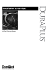
2. GENERAL SPECIFICATIONS
The Raypak Booster Heater is design certified and tested under the requirements of the American National
Standard, ANSI Z 21.10.3 ,and the Canadian National Standard, CAN 1-4.3-M85, and bears the National
Sanitation Foundation, NSF, seal.
The Raypak Booster Heater is an instantaneous tube type free standing unit intended for use as a supplier
of 180 Deg. F dishwasher rinse water. Inlet water temperature to the heater of 140 deg. F is required for optimum
operation of the heater.
Water enters the heat exchanger from the heater inlet water connection. The water then is circulated through
two passes of copper finned tubes, through a stainless steel tank and to the dishwasher. Water is also recirculated through a bypass system that assures the availability of the proper temperature water at the heater
outlet.
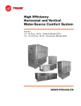
SPECIFICATIONS AND DIMENSIONS
Model
B-195
Input
MBH
195
40°F
490
GPH Delivery at Indicated Temperature Rise
50°F 60°F 70°F 80°F 100°F 120°F 140°F
392
327
280
245
196
163
140
Fig #9165
3
3. INSTALLATION PROCEDURES.
CODE REQUIREMENTS
Installation must be in accordance with local codes, or in the absence of local codes with the latest edition
of the National Fuel Gas Code, ANSI Z223.1, the National Electrical Code, ANSI/NFPA 70. For Canada, CAN/
CGA B149.1 and .2, and CSA C22.2 No. 1.
LEG INSTALLATION
Four (4) legs are supplied loose within the carton for installation at the site. This will provide the required sixinch clearance off the floor. To install the legs, raise one end of the heater just high enough to allow the legs to
be screwed into the two corners of that end. Make sure each leg is tightened securely by hand. Lower the heater
gently to minimize any undue strain on the two (2) legs. Gently raise the other end, and repeat the same procedure
for the other two (2) legs. Rotate the lower section of each leg as necessary to level the heater in place.
Booster water heater should not be located in an area where water leakage will result in damage to the area
adjacent to it or to lower floors of the structure. Where such areas cannot be avoided, it is recommended that
a suitable catch pan, adequately drained, be installed under this heater. Do not install directly on carpeting.
CLEARANCE REQUIREMENTS
Floor Top
Left
Right
Side
Side
*
0"
6"
6"
*Approved for installation on combustible flooring.
Front
Back
Vent
Alcove
6"
1"
A front clearance of at least 24" is recommended for adequate service of burner-tray and controls.
COMBUSTION/VENTILATION AIR
B195 COMBUSTION AIR ADJUSTMENT
This model is equipped with an air adjustment screw on the combustion air blower inlet. For natural gas the
opening is factory set at about 2.12" diagonal dimension, for propane gas the opening is 1.875" diagonal
dimension, which should be the proper setting for most installations. However, field conditions including unusual
gas characteristics may create a need for adjustment to achieve optimum performance. When the combustion
air setting is proper, there will be some lifting of the flames on some areas of the burner tile under cold start
conditions. After about five minutes of operation, the flames should settle down and blue tips should become
visible on some areas and orange glow on other sections of the burner tile. Lifting of flames beyond five minutes
would indicate too much combustion air. The adjustment screw should be turned clockwise to reduce the
combustion air supply until the lifting settles down. If the blue tips disappear and the entire burner surface
becomes radiant white, it indicates that there is not enough combustion air and the adjustment screw should be
turned counterclockwise to increase the combustion air opening until the blue tips and orange glow become
visible again.
The optimum excess air will result in CO2 levels between 8 and 8.5% for natural gas and 9.2 to 9.7% for
propane. If a flue gas analyzing equipment is available, the opening can be adjusted to achieve this CO2 level.
Or, if an inclined manometer is available, pressure measured at the combustion air switch pressure tap, can be
set at -0.35" W.C. for natural gas and -0.60" W.C. for propane by means of the adjustment screw. Pressure at
this level will result in the proper CO2 levels mentioned above.
Again, the factory setting will be adequate for most field conditions and adjustment will not normally be
required.
CAUTION: A dusty kitchen environment combined with greasy laden air will clog the combustion air blower wheel
and cause premature failure of the heater. Combustion air must not be contaminated by corrosive chemical
fumes which can severely damage the heater.
4
Measures must be taken to prevent the entry of corrosive chemical fumes to the combustion and ventilation
air supply. Such chemicals include, but are not limited to, chlorinated and/or fluorinated hydrocarbons such as
found in refrigerants, aerosol propellants, dry-cleaning fluids, degreasers, and paint removers. Other harmful
elements may come from bleaches, air fresheners, or mastics. Vapors from these types of products can form
corrosive acid compounds when burned in a gas flame. The resulting acid condensate can damage or
substantially reduce the life of the heater. It may be necessary to provide outside air directly to the heater in order
to avoid this problem.
An adequate supply of air for proper combustion and ventilation must be provided in accordance with Sec.
5.3 of the National Fuel Gas Code, ANSI Z223.1. or applicable provisions of the local building codes.
Do not obstruct the flow of combustion and ventilation air to the heater.
VENTING
The vent pipe must be the same size or larger than the 4" diameter outlet on the heater. The standard vent
outlet is on the right side, but this can be changed to the left side by reversing the orientation of the flue collector
box. This can be done easily in the field. Remove the top casing cover to gain access to the flue collector box.
Remove the screws along the sides of the flue collector. Disconnect the vent switch tubing from the fitting and
remove the fitting from the flue collector box. Lift the box and turn around the other direction. Remove the
stainless steel plug button and install the fitting in its place; then install the plug button where the fitting was
removed. Reconnect the vent switch tubing to the fitting. Replace and secure the flue collector box with the
screws previously removed.
The maximum flue gas temperature at the heater outlet is less than 400 degrees F. Use only the special gas
vents listed for use with Category III gas burning heaters, such as the stainless steel Saf-T Vent manufactured
by Heat-Fab, Inc. (800-772-0739), or the StaR-34 stainless steel gas vents manufactured by Flex-L International,
Inc. (800-561-1980), of the FasNSeal stainless steel gas vents manufactured by ProTech Systems, Inc. (800766-3473). A special adapter may be required. Pipe joints must be positively sealed. Follow carefully the vent
manufacturers' installation instructions.
WARNING: Provide a screen or barrier to prevent personal injury in areas where personnel contact with vent pipe
can occur; but DO NOT INSULATE the vent pipe, nor use means that will restrict thermal expansion or movement
of the vent.
5
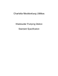
Applies only to exhaust hood over cooking equipment.
Fig. #8975.3
6
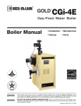
All horizontal runs of the vent pipe shall have a
minimum rise of 1/4" per foot of length and should be
supported at maximum intervals of 5 feet (for Canada,
3 feet) and at each point where an elbow is used.
The gas booster heater may be vented 3 ways:
For horizontal venting, the total length of 4-inch
diameter pipe shall not exceed 30 feet with up to two
90° elbows and 1 termination vent. For each additional
elbow, reduce the total pipe length by 10 feet. The
minimum length, in either case, is 2 feet with two
elbows ending in a termination vent. For vertical
venting, the lengths described above should be followed, with a termination vent at the top. The minimum
length is 5 feet with up to two elbows and a termination
vent.
2. Into the exhaust system. (See illustration on page
6) Vent pipe must not penetrate filter.
1. Through the sidewall, or the ceiling, as discussed
previously.
When the unit is vented into the exhaust system, an
electrical inter-lock must be provided to allow the
flow of gas to the booster heater burner ONLY
when the exhaust system is energized.
3. Free vented into a room or space where other gas
fired equipment is installed, provided that one or
more of the other installed equipment is furnished
with a venting system or other approved means for
removing the vent gases so the aggregate input of
the remaining unvented equipment, including the
booster heater, does not exceed 20 BTU per hour
per cubic foot of volume. The volume of a room or
space directly connected by a doorway, archway or
other opening of comparable size that cannot be
closed, may be included in the calculations. Refer
to the National Fuel Gas Code ANSI Z223.1, NFPA
54.
For sidewall venting, locate the heater as close as
possible to the wall being used. The maximum and
minimum wall thickness is determined by the wall
thimble available from the vent manufacturer. Refer to
the vent manufacturer installation instructions.
Additional requirements when venting through a
sidewall:
1. The vent terminal shall be located at least three feet
above any forced air inlet located within ten feet;
or at least four feet below, four feet horizontally
from, or one foot above any door, window, or
gravity air inlet into any building.
It shall also have a minimum horizontal clearance
of four feet from electric meters, gas meters,
regulator and relief equipment.
2. The vent terminal shall be located not less than
seven feet above grade when it is adjacent to
public walkways.
3. The bottom of the vent terminal shall be located at
least twelve inches above grade or ground, or
normally expected snow accumulation level. The
snow level may be higher on walls exposed to
prevailing winds.
4. Avoid areas where local experience indicates that
condensate drippage may cause problems such
as above planters, patios, or over public walkways, or over an area where condensate or vapor
could create a nuisance or hazard, or could be
detrimental to the operation of regulators, relief
valves, or other equipment.
7
GAS PIPING
The gas inlet pipe size is 1/2" NPT to the gas valve.
Provide an adequate size gas supply line. The line
should not be smaller than 1/2" NPT according to the
chart below.
MAXIMUM EQUIVALENT PIPE LENGTH (FEET)
Gas
Natural
Propane
Pipe Size
1/2"
3/4"
5
30
70
1"
100
180
Gas piping must have a sediment trap ahead of the
heater gas controls and a manual shut-off valve located outside the jacket. A manual shut-off valve is
provided loose and must be installed at the site.
Fig. # 8984
The heater and its gas connection shall be leak
tested before placing the heater in operation.
The heater and its individual shut-off valve must be
disconnected from the gas supply piping system during
any pressure testing of that system at test pressures in
excess of 1/2 psig (3.5 kPa).
GAS PRESSURE SPECIFICATIONS
Inches
W.C.
Gas
Min
Max
Manifold
Natural
4.5
10.5
3.5
Propane
11.0
14.0
10.0
The heater must be isolated from the gas supply
piping system by closing its individual manual shut-off
valve during any pressure testing of the gas supply
piping system at test pressures equal to or less than
1/2 psig (3.5 kPa).
The maximum inlet gas pressure must not exceed
the value shown above. The minimum gas pressure
shown is for the purposes of input adjustment.
Dissipate test pressure from the gas supply line
before re-connecting the heater and its manual shut-off
cock to the gas supply line. FAILURE TO FOLLOW
THIS PROCEDURE MAY DAMAGE THE GAS VALVE.
OVER PRESSURED GAS VALVES ARE NOT COVERED BY THE WARRANTY. The heater and its gas
connections shall be leak tested before placing the
appliance in operation. Use soapy water for leak test.
DO NOT use open flame.
The gas valve is provided with a pressure tap to
measure the gas pressure downstream, which is also
the manifold pressure.
WATER PIPING
The inlet and outlet water connections are 3/4 in.
NPT. A water pressure regulator is shipped loose with
the heater. Install, as needed, between the booster
heater and dishwasher lines. Adjust setting to maintain
20 PSI at the dishwasher.
NOTE: DO NOT use teflon tape on gas line pipe
threads. A flexible sealant suitable for use with Natural
and Propane gases is recommended.
Install a suitable water hammer arrester between the booster heater and dishwasher, as shown
on page 10, typical piping.
8
A drain valve is provided in the tank for draining
water during servicing.
The temperature and pressure relief valve is easily
accessible through the front. A nipple is provided
(shipped loose with the heater) for installation in the
T & P relief valve. A drain line must be connected to
the nipple and run to a safe place of disposal.
WARNING: Failure to do so can cause water damage
or burns due to scalding if the relief valve should open.
Drain line must be as short as possible, pitch downward
from the relief valve, and have the same size as the
valve discharge connection through-out its entire length.
Refer to tag attached to T & P relief valve.
The temperature and pressure relief valve should
be manually operated at least once a year to insure that
the valve mechanism is still functional. Repair or
alteration of valve in any way is prohibited by National
Safety Standards and or local codes.
If the relief valve discharges occasionally or periodically, this may be due to thermal expansion in a
closed water supply system. Contact the water supplier or the local plumbing inspector on how to correct
this situation. DO NOT plug the relief valve or install
a shut-off valve in the discharge drain line.
The heater is equipped with a circulator to provide
the minimum water flow in the heater, and maintain a
uniform water temperature in the tank. Depending on
heater distance from the dishwasher, it may be necessary to run empty rack(s) to purge supply of line lower
than the required 180°F water temperature. For this
reason, it is best to locate heater as close as possible
to the dishwasher.
CAUTION: In severe cold weather, freezing air can be
drawn through the vent pipes to the heat exchanger
during overnight shut-down period. If there is no water
circulation or heat in the water, freezing can occur
which will damage the heat exchanger. To avoid
freezing damage, constant water circulation should be
maintained by keeping the booster heater energized
so that the circulator (pump) will run. Closing the
manual gas shut-off valve will prevent unnecessary
heating of the water. NOTE: Under this condition, the
ignition system will go into a lock-out mode. To resume
service, the heater will need to be reset by momentarily
turning the ON/OFF switch to the OFF position, and
then to the ON position.
9
ELECTRICAL
The electrical power supply requirement for the heater is 120 volts, 60 Hz, 5.0 amps or less . Field wiring
connections and electrical grounding must comply with the local codes, or in the absence of local codes, with
the latest edition of the National Electrical Code, ANSI/NFPA 70.
NOTE: Polarity must be observed for the heater to operate properly. Consult wiring diagram. Provide a separate
fused circuit from the main electrical panel to the heater and a disconnecting means within sight of the heater.
Remove the control box cover and make the power supply connection in the field wiring compartment. The
pump and blower supplied with the heater are pre-wired and operate with the heater control system.
NOTE: If it is necessary to replace any of the original wiring it must be replaced with 105° C rated wire or its
equivalent.
10
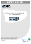
LADDER DIAGRAM
CONNECTION DIAGRAM
DANGER: SHOCK HAZARD
Turn off electrical power to boost heater before servicing any
component in the heater to prevent equipment damage or
personal injury.
NOTE: If it is necessary to replace any of the original wiring, it
must be replaced with 105°C rated wire or its equivalent.
11
4. START UP AND OPERATION
COMPONENT LOCATION
SEQUENCE OF OPERATION
The booster heater is designed to maintain a temperature of 180 deg. F (82.2 Deg. C) of 490 GPH water
required for the rinse cycle of a commercial dishwasher. An inlet temperature of 140 Deg. F (60 Deg.
C) will produce optimum results.
Provided the necessary power, water, gas and
vent connections are completed, the unit is started by
the activation of the on/off switch located on the left side
panel. The blower motor and the circulator pump will
also start.
Providing the operating and safety controls including the vent switch is closed, the ignition module will
energize the ignitor. The hot surface ignitor then heats
up, and is proven to be capable of ignition. The gas
valve is then energized. The burner will be lit and the
remote sensor will sense the flame. If the burner flame
is not sensed within four seconds the gas valve will shut
off. The ignition module will try for a total of three cycles
to prove ignition. If, after third cycle ignition is not
proven, the module will go into lockout, and a Red-LED
will start blinking. To recycle the burner, momentarily
turn the power switch to the off position and then to the
on position. When the water temperature exceeds the
setting of the operating controller, the burner will shut
off until the next call for heat. The operating limit control
is factory set at 185°F. Combustion air blower and the
circulator pump will cycle On/Off with the operating limit
controller.
START UP PROCEDURES
SECTION 1. FILLING THE SYSTEM
Fill the heater system with water purging all air. It
is recommended that the system be flushed before
putting heater into operation . This can be done by
opening the drain valve located under the stainless
steel tank.
SECTION 2. CHECKING CIRCULATOR/PUMP
Before lighting the heater, make sure the circulator
is operating properly. With the gas valve in the off
position, activate the power switch. The circulator
should start immediately. Allow the circulator to pump
the water through the system.
NOTE: The circulator motor does not require lubrication.
12
SECTION 3. LIGHTING THE HEATER
Safety lighting and other performance criteria were
met for the burner assembly and control assembly
when the heater was tested for design certification
under the ANSI Z21.10.3 Standard
WARNING: If you do not follow these instructions
exactly, a fire or explosion may result causing property
damage, personal injury or loss of life.
A. This heater DOES NOT have a pilot. It is equipped
with a hot surface ignition device which automatically lights the burner. DO NOT attempt to light the
burner by hand.
B. Before operating smell all around the heater area
for gas. Be sure to smell next to the floor because
some gases are heavier than air and will settle on
the floor.
4. This appliance is equipped with an ignition
device which automatically lights the burners. Do
not try to light the burners by hand.
5. Push in and move gas control lever counter
clockwise
to "OFF" position.
6. Wait five (5) minutes to clear out any gas. If you
then smell gas. STOP! Follow "B" in the safety
information above on this label. If you don't smell
gas, go to next step.
7. Move gas control lever clockwise
to "ON"
position.
GAS CONTROL
LEVER SHOWN
IN "OFF"
POSITION
WHAT TO DO IF YOU SMELL GAS
•
•
•
•
•
Do not try to light any appliance.
Do not touch any electric switch.
Do not use any phone in your building.
Immediately call your gas supplier from a
neighbor's phone. Follow the gas supplier's
instructions.
If you cannot reach your gas supplier, call the
fire department.
C. Use only your hand to push in, move or turn the gas
control knob or lever. Never use tools. If the knob
or lever will not push in, move or turn by hand, don't
try to repair it, call a qualified service technician.
Force or attempted repair may result in a fire or
explosion.
D. Do not use this heater if any part has been under
water. Immediately call a qualified service technician to inspect the heater and to replace any part of
the control system and gas control which has been
underwater.
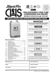
HOT SURFACE IGNITION MODELS WITH
ROBERTSHAW GAS VALVE
1. STOP! Read the safety information.
2. Turn off all electrical power to the appliance.
3. Remove front door and control box cover.
13
GAS INLET
Fig. # 8934.1
8. Replace control box cover and front door.
9. Turn on all electric power to the appliance.
10. If the appliance will not operate. Follow the
instructions "To Turn Off Gas To Heater" and call
your service technician or gas supplier.
TO TURN OFF GAS TO HEATER
1. Turn off all the electric power to the heater if service
is to be performed.
2. Remove front door and control box cover.
3. Push in and move gas control lever counter
clockwise
to "OFF".
CAUTION: Should overheating occur or the gas supply fails to shut off, DO NOT turn off or disconnect the
electrical supply to the pump. Instead, shut off the gas
supply at a location external to the appliance. Failure
to observe this precaution may aggravate the overheated condition resulting in possible damage to the
heater and injury to the user.
SECTION 4.
TESTING THE IGNITION SAFETY SHUT-OFF
The ignition system safety shut-off must be tested by
conducting the following method of tests:
3.
4.
5.
6.
Remove screws on burner access panel.
Remove refractory block.
Visaully inspect burner tray panel.
Reverse above procedure to reinstall, checking
burner tray and seal to prevent leakage.
a) With the system power off, manually shut off the
gas supply.
b) Turn power back on, observe the igniter start to
heat up and glow bright orange.
c) After about four (4) seconds, the gas valve is
energized, then de-energizes, after the third try the
module goes into a safety lockout a few
seconds later. Igniter will stop glowing and the R e d
LED on the module will start blinking.
d) Manually reopen the gas supply. No gas should be
flowing into the main burners. End of test.
ADJUSTMENTS/REPLACEMENTS
OF COMPONENTS
e) To reset the system, momentarily shut off power
switch then turn it back on again. Igniter will start
to heat up and normal heating cycle will occur as
described in the sequence of operation on page
12.
1. Gas Valve Replacement
a) Shut off electrical power and gas supply to the
heater.
b) Remove gas piping to gas valve inlet.
c) Remove front panel and leftside access panel.
d) Disconnect flex hose gas line.
e) Disconnect wiring connections to gas valve.
f) Remove (2) screws holding gas valve.
g) Reverse above procedure to reinstall.
MAINTENANCE INSTRUCTIONS
1. The water pump motor and the combustion air
blower motor are permanently lubricated and requires no other maintenance.
2. Venting system for this heater may be equipped
with high temperature plastic material rated for
operation at 480°F maximum. Check for signs of
deformation in the plastic vent pipes which will be
an indication of excessive temperature and abnormal conditions in the venting system. Refer to the
instructions supplied by the vent pipe manufacturer.
3. The burner is made of ceramic material and operates in the infrared mode. When the burner is
operating properly very little blue flame will be
visible due to the incandescent brightness of the
ceramic material. This can be observed through
the glass observation port hole.
4. Depending on the condition of the kitchen environment, the burner and blower wheel may require to
be cleaned of lint or grease-laden dust. Inspect the
burner box every six months. Refer to the Servicing Section related to burner removal.
BURNER INSPECTION/VISUAL
1. Shut-off electrical power and gas supply to the
heater.
2. Disconnect wiring to hot surface ignitor and sensor.
CAUTION: Label all wires prior to disconnection when
servicing controls. Wiring errors can cause improper
and dangerous operation. Verify proper operation after
servicing.
DANGER - SHOCK HAZARD - Make sure electrical
power to the heater is disconnected to avoid potential
serious injury or damage to components.
2. Hot Surface Ignitor Replacement
a) Shut off electrical power and gas supply to the
heater.
b) Disconnect wiring leads to the igniter by pulling
apart plastic connector plugs.
c) Remove bracket holding ignitor cylinder.
d) Reverse above procedure to reinstall.
CAUTION: Silicon carbide ignitor is fragile and brittle.
Exercise extreme care in handling the assembly to
avoid damage.
3. Ignition Module Replacement
a) Shut off electrical power to the heater.
b) Remove control cover screws and open control compartment.
c) Disconnect wiring connections to module.
d) Remove screws (2) holding module.
e) Reverse above procedure to reinstall.
4. Transformer Replacement
a) Shut off electrical power to the heater.
b) Remove control cover screws and open control compartment.
c) Disconnect wiring connections from transformer
leads.
d) Remove screws (2) holding transformer.
e) Reverse above procedure to reinstall.
14
5. Limit Control Module
a) Shut-off electrical power to the heater.
b) Remove control cover screws and open control compartment.
c) Disconnect wiring connections to the board.
d) Carefully pull out the control board from the
nylon pin supports.
e) Reverse above procedure to reinstall.
11. Combustion Air Blower Replacement
a) Shut off electrical power to heater.
b) Remove front panel and access cover on left
side of heater.
c) Remove screws (3) on blower housing mounting panel.
d) Drop down blower assembly from discharge
connection.
e) Open field wiring box and disconnect blower
wiring.
f) Reverse above steps to reinstall blower.
6. Sensor Probe Replacement
a) Shut off electrical power to the heater.
b) Shut off water supply to the heater and open
drain valve to remove water to the sensor
probe level.
c) Remove front panel and control box cover.
d) Disconnect wire leads from temperature control module.
e) Remove sensor probe from the header. Use
7/16" wrench.
f) Reverse above procedure to reinstall.
12. Pump/Circulator Replacement
a) Shut off electrical power to the heater.
b) Shut off water supply and open drain valve to
remove water in the piping at the pump level.
c) Remove front panel and access panel on right
side of cabinet.
d) Disconnect wiring and conduit connections to
motor.
e) Remove plumbing connections to pump assembly.
f) Reverse above procedure to reinstall.
7. Manual Reset High Limit Control Replacement
a) Shut off electrical power and water supply to
the heater.
b) Remove front panel and open drain valve to
remove water to the limit control level in the
tank.
c) Disconnect wiring connections to limit control.
d) Remove limit control from the tank. Use 1" hex
wrench, being careful not to break plastic body.
e) Reverse above procedure to reinstall.
13. Temperature and Pressure Relief Valve
Replacement.
a) Shut off electrical power to the heater.
b) Shut off water supply and open drain valve to
remove water in the tank to the relief valve
level.
c) Remove front panel.
d) Disconnect plumbing connections to the T & P
relief valve.
f) Reverse above procedure to reinstall.
8. Auto Reset High Limit Replacement
a) Shut off electrical power and water supply to
the heater.
b) Remove front panel and open drain valve to
remove water to the limit control level in the
header.
c) Disconnect wiring connections to limit control.
d) Remove limit control.
e) Reverse above steps to reinstall.
9. Air/Vent Switch Replacement
a) Shut off electrical power to the heater.
b) Remove front panel.
c) Remove wiring connections to switch.
d) Remove screws (2) holding the switch.
e) Reverse above procedure to reinstall.
10. Remote Sensor Replacement
a) Shut off electrical power & gas supply to the
heater.
b) Remove front panel.
c) Disconneect wiring lead from sensor.
d) Remove the screws (2).
e) Reverse above procedure to reinstall.
15
5. SERVICING UNIT
TROUBLE SHOOTING GUIDE
PROBLEM
POSSIBLE CAUSE
SUGGESTED SOLUTION
1. On-Off switch energized. Unit
does not operate.
1a. No power to heater
a. Cycle the Power Switch off then on.
-Check circuit breaker and electrical
disconnect.
-Check for reversed polarity and improper ground.
-Check dishwasher vent interlock, if
applicable.
1b. Defective transformer
b. Check secondary voltage.
If no 24 volts, replace transformer.
2a. Loose wire(s)
2a. Check wiring connection(s)
-Check pump amperage. If pump
does not draw 0.67-0.78 amps, remove and inspect impeller.
2b. Replace cartridge or entire pump as
needed.
2c. Clean and inspect blower wheel.
-Check operation.
-Replace blower if needed
2. Pump/Blower NOT running.
2b. Defective pump
2c. Defective blower.
3. Unit energized, pump and
blower running, but burner is
NOT on.
3a. Limit control (operating limit)
or sensor may be defective.
3a. If Red LED on circuit board is ON,
check for a loose sensor connection
or defective sensor. Sensor resistance readings:
60°F = 45,500± 2300 ohms
80°F = 28,000± 1300 ohms
If Yellow LED is ON , water temperature is above set point. When either
Red or Yellow LED is ON, heater will
be shut down. Check 24V, power at
OUT and COMM terminals. If no 24V
is present when Red or Yellow LED is
not ON, replace control board.
3b. Blocked vent or defective
air vent switch.
3b. Excessive vent length or resistance
or blocked vent will open the air vent
switch. Remove blockage. If switch
stays open, replace air vent switch.
3c. Tripped or defective manual
reset limit.
3c. Depress the Manual Reset High Limit
switch.
-Ensure Operating Limit setting is
185°F or less.
-Perform Pump Check Procedure.
(High Limit trips may be due to a
damaged pump).
-Perform Operating Limit Check
Procedure.
-If High Limit will not reset, replace
High Limit
16
Continuation TROUBLE SHOOTING GUIDE
4. Unit energized, pump and
blower running.
Ignitor is glowing.
Burners will not stay lighted.
3d. Excessive vent exhaust or
defective air/vent switch.
3d. Excessive negative pressure exerted
by the exhaust system on the vent will
prevent N.O. combustion air/vent
switch from closing. Provide means to
relieve pressure and close the N.O.
switch. If combustion air/vent switch
will not close, replace switch.
3e. Ignition module or igniter
may be defective.
3e. Disconnect igniter leads from ignition
module. Make sure 24V is present
across ignition terminals on the ignition module during the ignition cycle.
If not, replace ignition module. Check
resistance reading across igniter
leads. If circuit is open, or reading is
greater than 30 ohms, replace the
igniter. A new igniter will measure
between 1 to 6 ohms at room temperature.
3f. Gas valve or the ignition
module may be defective.
3f. During the ignition cycle, 24V should
be present at the MV1 and GND terminals for about 5 seconds. If no 24V is
measured, replace the ignition module. If 24V is present, replace the gas
valve.
4a. Improper ground
4a. Check ground connections inside
control box.
4b. Check all connections and wire nuts.
4c. Check wire connection to remote sensor.
4d. Check gas pressure at outlet of valve
under load, pressure should be:
3.5 in. W.C.for Natural gas
10.5 in. W. C. for Propane gas.
4b. Loose wiring.
4c. Remote sensor
4d. Insufficient gas pressure.
5
Unit does not produce
suffcient hot water
5a. Supply water temperature
too low.
5b. Dishwasher times not set
properly.
5c. Operating limit set too low.
17
5a. Ensure supply water temperature is at
least 140°F.
5b. Ensure dishwasher operates correctly.
Check rinse cycle time and inspect
spray nozzles for correct pressure
setting or damage.
5c. Adjust operating limit to minimum temperature that provides 180°F rinse.
(Do not set above 185°F).
-Verify booster operates correctly, if
not, recheck all procedures listed
above.
6. REPLACEMENT PARTS LIST
NOTE: To supply the correct part it is important that you state the model number, serial number and type of gas
when applicable.
Any part returned for replacement under standard company warranties must be properly tagged with
RAYPAK return parts tag, completely filled in with the heater Serial Number, Model Number etc., and shipped
to the Company freight prepaid.
If determined defective by the Company and within warranty, the part will be returned in kind or equivalent
substitution, freight collect. Credit will not be issued.
RAYPAK, INC.
2151 Eastman Avenue
Oxnard, CA 93030
18
19
20
21
LIMITED PARTS WARRANTY
COMMERCIAL BOOSTER HEATER
SCOPE:
Raypak, Inc. ("Raypak") warrants to the owner that all parts of this booster heater, excluding controls and pump, will
be free from failure under normal use and service for the specified warranty periods and subject to the conditions set forth
in this Warranty. The Warranty is effective from date of original booster heater installation and satisfactory proof of the original
installation date, such as installer invoice, is required. THIS WARRANTY WILL BE VOID IF THE HEATER IS NOT
INSTALLED IN ACCORDANCE WITH LOCAL CODES AND ORDINANCES OR IF THE HEATER RATING PLATE IS
ALTERED OR REMOVED OR IF THE HEATER IS MOVED FROM ITS ORIGINAL PLACE OF INSTALLATION.
HEAT EXCHANGER WARRANTY:
• Five (5) Years. This includes only the copper and bronze waterways.
• Twenty (20) Years against "Thermal Shock" (excluded, however, if caused by booster heater operating at large
changes exceeding 150°F between the water temperature at intake and booster heater temperature, or
operating at booster heater temperatures exceeding 200°F).
TOTAL FIVE YEAR STAINLESS STEEL TANK WARRANTY:
• First Year: Raypak will replace the tank if it fails under normal use and service.
• 2nd thru 5th Year: Raypak will replace the tank if it fails under normal use and service, provided that the owner must
pay Raypak a portion of the published list price in effect at the time notice of the failure is given.
REPLACEMENT PRICE)
REPLACEMENT PRICE
YEAR OF CLAIM
(PERCENT OF LIST PRICE
YEAR OF CLAIM
(PERCENT OF LIST PRICE)
2
20%
4
60%
3
40%
5
80%
ANY OTHER PART MANUFACTURED BY RAYPAK:
One (1) Year Warranty, or eighteen (18) months from date of factory shipment based on Raypak's records,
whichever comes first.
PARTS REPLACEMENT
Under this Warranty, Raypak will furnish a replacement for any failed part. Verification of the in-warranty failure will be
made through inspection by a local recognized and certified service agency or the local Raypak representative at Raypak's
option. The replacement part will be warranted for only the unexpired portion of the original warranty. Raypak makes no
warranty whatsoever on the controls and the pump, but Raypak will apply any such warranties as may be provided to it by
the part's manufacturer.
LABOR CHARGES
Labor charges to replace any failed part during the first 90 days of this Warranty, will be paid by Raypak. Service must
be performed by a recognized and certified service agency during normal working hours. All other costs are excluded from
this warranty and are the owners responsibility.
ADDITIONAL WARRANTY EXCLUSIONS:
This Warranty does not cover failures or malfunctions resulting from:
1. Failure to properly install, operate or maintain the booster heater in accordance with our printed instructions;
2. Abuse, alteration, accident, fire, flood and the like;
3. Sediment or lime buildup, freezing or other conditions causing inadequate water circulation;
4. High velocity flow exceeding booster heater design rates;
5. Failure of connected systems devices, such as pump or controller;
6. Use of non-factory authorized accessories or other components in conjunction with the booster heaters.
7. Failure to eliminate air from, or replenish water in, the connected water system;
8. Chemical contamination of combustion air or owner's use of chemical additives to water.
TO MAKE A WARRANTY CLAIM:
Promptly notify the selling dealer, supplying model and serial numbers and description of the problem. The dealer must
then notify it's Raypak distributor for instructions regarding the claim. If the dealer is not available, contact SERVICE
MANAGER, at the address listed below. In all cases, proper authorization must first be received from Raypak before any part
is replaced. Any replaced part must be made available to Raypak in exchange for replacement.
EXCLUSIVE WARRANTY - LIMITATION OF LIABILITY:
This is the only warranty given by Raypak. No one is authorized to make any other warranties on Raypak's behalf. ALL
OTHER WARRANTIES, EXPRESS OR IMPLIED, INCLUDING BUT NOT LIMITED TO THE IMPLIED WARRANTIES OF
MERCHANTABILITY AND FITNESS FOR A PARTICULAR PURPOSE, ARE EXCLUDED. Some States do not allow
limitations on how long an implied warranty lasts, or for the exclusion or incidental or consequential damages, so the above
limitation or exclusion may not apply to you.
THIS LIMITED WARRANTY GIVES YOU SPECIFIC LEGAL RIGHTS. YOU MAY ALSO HAVE OTHER RIGHTS WHICH
VARY FROM STATE TO STATE.
The sole remedy against Raypak with respect to defective parts shall be as provided in this Warranty. It is agreed that Raypak
shall have no liability, whether under this Warranty, or in contract, tort, or otherwise, for any special, consequential, or
incidental damages.
RAYPAK, INC., 2151 Eastman Avenue, Oxnard, CA 93030 (805) 278-5300
23
www.raypak.com
Raypak, Inc., 2151 Eastman Avenue, Westlake Village, CA 93030 (805) 278-5300 FAX (800) 872-9725
Raypak Canada Limited, 2805 Slough St., Mississauga, Ontario, Canada L4T 1G2 (416) 677-7999 FAX (416) 677-8036
Litho in U.S.A.