1
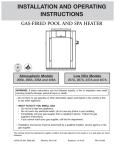
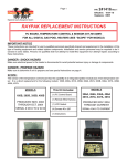
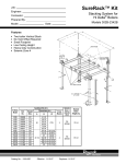
P/N 241169 Rev.-3
Page 1
RAYPAK REPLACEMENT INSTRUCTIONS
P.C. BOARD, TEMPERATURE CONTROL & SENSOR (KIT #010253F) FOR ALL
DIGITAL GAS POOL HEATERS (SEE “SCOPE” FOR APPLICABLE MODELS)
IMPORTANT NOTICE
These instructions are intended primarily for use by qualified personnel specifically trained and experienced in the installation of this
type of heating equipment and related system components. Installation and service personnel may be required to be licensed in
some states. Persons not qualified shall not attempt to install this equipment nor attempt repairs according to these instructions.
DANGER - SHOCK HAZARD
Make sure electrical power to the heater is disconnected to avoid potential serious injury or damage to components.
DANGER - PROPANE HAZARD
Make sure to determine if unit is propane and see special instructions on page 6.
SCOPE:
This version of the temperature control board has the capability of an integrated ignition module plus 3-wire temperature sensor.
The kit includes a gasket and a plastic shield that is mounted to the back side of the control panel to eliminate moisture
accumulation on the LCD display. It is a direct replacement for the following models: 185A, 185B, 206A, 207A, 265A, 265B, 266A,
267A, 335A, 335B, 336A, 337A, 405A, 405B, 406A, 407A.
This kit includes
(1) P.C. control board
(1) PC board plastic shield
(2) Brackets
(1) Temperature sensor
(6) Plastic #8 washer
(1) LCD Gasket
(1) Remote wire harness
(1) Hi tension wire extension
(4) Screws #6 X 3/8"
(6) Screws #8 X 1/2"
(2) Screws #10 X 1/2"
(1) Instructions
ew
e n rd
Th boa r
e
le
sty larg old
is the rd
a
n
tha le bo
sty
MODELS
MODELS
MODELS
185A, 265A, 335A, 405A
185B, 265B, 335B, 405B
PRODUCED NOV. 1998
THROUGH OCT. 2003
SERIAL # 9811 TO # 0310
PRODUCED NOV. 2003
THROUGH OCT. 2004
SERIAL # 0310 TO # 0410
206A, 207A, 266A, 267A,
336A, 337A, 406A, 407A
PRODUCED OCT. 2004THROUGH CURRENT
SERIAL # 0410 - CURRENT
2151 Eastman Ave., Oxnard, CA 93030 805-278-5300 Fax 800-777-7026 www.raypak.com
Technical support is available M-F, 5:30 AM to 5:00 PM PST, at 800-947-2975 or 800-627-2975
P/N 241169 Rev.-3
Page 2
ACCESSING THE BOARD - MODELS
185A/B, 265A/B, 335A/B, 405A/B:
1. Turn off the power to the heater.
2. Turn off the gas to the heater.
3. Remove front door.
4. Remove the four screws on the side of the heater
holding the control panel. See Fig. 1 and Fig. 2.
5. Lay control panel forward toward you to access the
back of the temperature control board.
r
r
Fig. 1
REMOVE THESE
SCREWS
ACCESSING THE BOARD - MODELS
206A, 207A, 266A, 267A, 336A, 337A, 406A, 407A:
1. Turn off the power to the heater.
2. Turn off the gas to the heater.
3. Remove front door by removing the large door
screw shown in Fig. 3.
4. Remove the four screws on the side of the control
panel. See Fig. 5 and Fig. 6.
5. Lay control panel forward toward you to access the
back of the temperature control board.
Fig. 2
REMOVE THESE SCREWS
REMOVE THESE
SCREWS
LARGE
DOOR
SCREW
Fig. 5
r
Fig. 3
Fig. 4
Close-up
r
Fig. 6
2151 Eastman Ave., Oxnard, CA 93030 805-278-5300 Fax 800-777-7026 www.raypak.com
Technical support is available M-F, 5:30 AM to 5:00 PM PST, at 800-947-2975 or 800-627-2975
P/N 241169 Rev.-3
Page 3
REMOVING THE CIRCUIT BOARD - MODELS
185A/B, 265A/B, 335A/B, 405A/B:
Make sure the power and gas are off.
1. Unplug all connectors from old circuit board. Fig. 7.
2. Unplug keypad ribbon from old circuit board.
3. Remove four screws as shown in Fig. 8.
4. Remove old circuit board.
UNPLUG ALL CONNECTORS
2.2
REMOVE KEYBOARD
RIBBON
Fig. 7
REMOVE MOUNTING SCREWS
Fig. 8
2151 Eastman Ave., Oxnard, CA 93030 805-278-5300 Fax 800-777-7026 www.raypak.com
Technical support is available M-F, 5:30 AM to 5:00 PM PST, at 800-947-2975 or 800-627-2975
P/N 241169 Rev.-3
Page 4
REMOVING THE CIRCUIT BOARD - MODELS 206A,
207A, 266A, 267A, 336A, 337A, 406A, 407A:
Make sure the power and gas are off.
1. Unplug all connectors from old circuit board. Fig. 9.
2. Unplug keypad ribbon from old circuit board.
3. Remove screws as shown in Fig. 10.
4. Remove old circuit board.
UNPLUG
ALL CONNECTORS
REMOVE KEYBOARD
RIBBON
Fig. 9
REMOVE MOUNTING SCREWS
Fig. 10
2151 Eastman Ave., Oxnard, CA 93030 805-278-5300 Fax 800-777-7026 www.raypak.com
Technical support is available M-F, 5:30 AM to 5:00 PM PST, at 800-947-2975 or 800-627-2975
Page 5
P/N 241169 Rev.-3
DISCONNECTING IGNITION CONTROL - MODELS 185A, 265A, 335A, AND 405A ONLY:
Make sure the power and gas are off.
1. Unplug all wires and connectors from ignition control. (See Fig. 11.)
Note: The ignition control is now part of the new
control circuit board. Old module
can be left in place but not used.
UNPLUG ALL WIRES
Fig. 11
2151 Eastman Ave., Oxnard, CA 93030 805-278-5300 Fax 800-777-7026 www.raypak.com
Technical support is available M-F, 5:30 AM to 5:00 PM PST, at 800-947-2975 or 800-627-2975
Page 6
P/N 241169 Rev.-3
PROPANE HEATERS ONLY:
Make sure the power and gas are off.
1. Locate the propane tab on the board as shown in Fig. 12.
2. Break off tab with pliers as shown in Fig. 13 & Fig. 14.
PROPANE
TAB
Fig. 13
Fig. 12
BROKEN TAB
Fig. 14
2151 Eastman Ave., Oxnard, CA 93030 805-278-5300 Fax 800-777-7026 www.raypak.com
Technical support is available M-F, 5:30 AM to 5:00 PM PST, at 800-947-2975 or 800-627-2975
Page 7
P/N 241169 Rev.-3
MODELS 185, 265, 335 & 405, A & B SERIES, LOW NOX ONLY:
Make sure the power and gas are off.
1. DO NOT break tab See Fig. 15 and Fig.16.
2. No additional wiring or connections are necessary.
DO
NOT
break
tab.
Fig. 15
Fig. 16
2151 Eastman Ave., Oxnard, CA 93030 805-278-5300 Fax 800-777-7026 www.raypak.com
Technical support is available M-F, 5:30 AM to 5:00 PM PST, at 800-947-2975 or 800-627-2975
Page 8
P/N 241169 Rev.-3
LOW NOX MODELS 207A, 267A, 337A & 407A:
Make sure the power and gas are off.
1. Locate Lo Nox tab and P-10 air switch terminal on the board as shown in Fig. 17 and Fig. 18.
2. Break off tab shown in Fig. 19 with pliers.
3. Attach the wire from the air switch to the P-10 location shown in Fig. 20.
P-10
TERMINAL
LO NOX
TAB
BREAK
TAB
Fig. 17
WIRE AIR
SWITCH
TO P-10
HERE
Fig. 18
BROKEN TAB
P–10 TERMINAL
Fig. 19
Fig. 20
2151 Eastman Ave., Oxnard, CA 93030 805-278-5300 Fax 800-777-7026 www.raypak.com
Technical support is available M-F, 5:30 AM to 5:00 PM PST, at 800-947-2975 or 800-627-2975
Page 9
P/N 241169 Rev.-3
NEW CIRCUIT BOARD & GASKET INSTALLATION USING OLD BEZEL - MODELS 185, 265,
335 & 405, A & B SERIES:
Make sure the power and gas are off.
Note: Disregard window gasket installation if already present.
1. Remove backing on gasket and install adhesive side on the control panel bezel as shown in
Fig. 21.
2. Re-assemble with new board to plastic bezel using the three mounting screws as shown in
Fig. 22 & Fig. 23.
GASKET
STICKY SIDE TO
PLASTIC BEZEL
REMOVE BACKING
LAY BOARD
DOWN
CLEAR
WINDOW
Fig. 21
RE-ASSEMBLE WITH NEW BOARD
MOUNTING SCREWS
Fig. 22
NOTE: DO NOT
RE-INSTALL
SCREW HERE
Fig. 23
2151 Eastman Ave., Oxnard, CA 93030 805-278-5300 Fax 800-777-7026 www.raypak.com
Technical support is available M-F, 5:30 AM to 5:00 PM PST, at 800-947-2975 or 800-627-2975
Page 10
P/N 241169 Rev.-3
GASKET & NEW CIRCUIT BOARD NEW BEZEL INSTALLATION - MODELS 206A, 207A,
266A, 267A, 336A, 337A, 406A, 407A:
Make sure the power and gas are off.
Note: Disregard window gasket installation if already present.
1. Remove backing on gasket and install adhesive side on the control panel bezel
as shown in Fig. 24 & Fig. 25.
2. Re-assemble with new board to plastic bezel using the three mounting screws
as shown in Fig. 26.
GASKET
ADHESIVE SIDE TO
PLASTIC BEZEL
REMOVE BACKING
LAY BEZEL
DOWN
CLEAR
WINDOW
Fig. 24
Fig. 25
RE-ASSEMBLE WITH NEW BOARD
MOUNTING SCREWS
NOTE: DO NOT
RE-INSTALL
SCREW HERE
Fig. 26
2151 Eastman Ave., Oxnard, CA 93030 805-278-5300 Fax 800-777-7026 www.raypak.com
Technical support is available M-F, 5:30 AM to 5:00 PM PST, at 800-947-2975 or 800-627-2975
Page 11
REMOVING & REPLACING SENSOR - MODELS
185, 265, 335 & 405, A & B SERIES:
P/N 241169 Rev.-3
LOOSEN DRAIN
PLUG TO
RELIEVE
PRESSURE
Make sure the power and gas are off.
1. Loosen drain plug to relieve pressure in heat
exchanger. See Fig. 27.
2. Remove five screws and in/out access panel
as shown in Fig. 28.
3. Re-route the 2-wire sensor connector from
the board (P1) back towards the in/out header.
4. Unscrew compression nut and loosen
compression fitting to replace old sensor
with new sensor. See Fig. 29.
5. Install new sensor and tighten compression
Fig. 28
fitting and compression nut.
6. Re-route the new 3-wire sensor connector back
to the board.
7. Plug the 3-wire sensor connector to its correct location,
P1, shown in Fig. 30 and close up in Fig. 31.
Fig. 27
REMOVE THESE 5
MOUNTING SCREWS
UNSCREW
COMPRESSION
NUT
NEW 3-WIRE
SENSOR
LOCATION
LOOSEN
COMPRESSION
FITTING
Fig. 29
Fig. 30
Fig. 31
2151 Eastman Ave., Oxnard, CA 93030 805-278-5300 Fax 800-777-7026 www.raypak.com
Technical support is available M-F, 5:30 AM to 5:00 PM PST, at 800-947-2975 or 800-627-2975
Page 12
P/N 241169 Rev.-3
PLASTIC SHIELD & BRACKET INSTALLATION MODELS 185, 265, 335 & 405, A & B SERIES:
SHIELD
BRACKETS
Make sure the power and gas are off.
1.
Note that the plastic shield is installed under the
front bracket as pictured.
Install the shield brackets and plastic shield using
the existing screws on the control panel as shown
in Fig. 32.
2.
Reconnect the wire harnesses to the board.
(Note the location of the clear plastic strip with the
thin connector. This is sometimes disconnected
when there is a remote control in the system.
Refer to the remote wiring instructions for further
details.)
Note: Make sure 3-wire sensor plug is connected.
3.
Install the plastic shield over the board and attach
to the brackets using the screws and washers
provided in the kit. See Fig. 33 and Fig. 34.
4.
Re-install the sheet metal panel holding the board
back into the heater.
5.
CLEAR PLASTIC STRIP
WITH THIN CONNECTOR
Fig. 32
Fig. 33
Go to remote operation instructions.
OR
Return the control panel to the upright position
and re-attach using the screws previously
removed.
SIDE VIEW
Fig. 34
2151 Eastman Ave., Oxnard, CA 93030 805-278-5300 Fax 800-777-7026 www.raypak.com
Technical support is available M-F, 5:30 AM to 5:00 PM PST, at 800-947-2975 or 800-627-2975
Page 13
P/N 241169 Rev.-3
INSTALLING PILOT HI TENSION: 206 TO 267A:
Ensure the power and the gas has been shut
off.
1. Re-connect pilot wire (side B) to new board. See
Fig. 35.
Fig. 35
INSTALLING PILOT HI TENSION WIRE EXTENSION SIZES 335A TO 407A:
Ensure the power and the gas has
been shut off.
1. Re-connect pilot wire (side B) to new
board with new extension Fig. 36 &
Fig. 37.
2. Connect side ‘A’ to existing pilot wire
and center protective sleeve over
connection.
CONNECT THIS END
TO EXISTING PILOT
WIRE
CONNECT THIS END
TO NEW PC BOARD
SPARK LUG
EXISTING PILOT
WIRE
Fig. 36
Side
‘B’
Side
‘A’
Fig. 37
2151 Eastman Ave., Oxnard, CA 93030 805-278-5300 Fax 800-777-7026 www.raypak.com
Technical support is available M-F, 5:30 AM to 5:00 PM PST, at 800-947-2975 or 800-627-2975
Page 14
P/N 241169 Rev.-3
2151 Eastman Ave., Oxnard, CA 93030 805-278-5300 Fax 800-777-7026 www.raypak.com
Technical support is available M-F, 5:30 AM to 5:00 PM PST, at 800-947-2975 or 800-627-2975
Page 15
P/N 241169 Rev.-3
2151 Eastman Ave., Oxnard, CA 93030 805-278-5300 Fax 800-777-7026 www.raypak.com
Technical support is available M-F, 5:30 AM to 5:00 PM PST, at 800-947-2975 or 800-627-2975
Page 16
P/N 241169 Rev.-3
2151 Eastman Ave., Oxnard, CA 93030 805-278-5300 Fax 800-777-7026 www.raypak.com
Technical support is available M-F, 5:30 AM to 5:00 PM PST, at 800-947-2975 or 800-627-2975
Page 17
P/N 241169 Rev.-3
2151 Eastman Ave., Oxnard, CA 93030 805-278-5300 Fax 800-777-7026 www.raypak.com
Technical support is available M-F, 5:30 AM to 5:00 PM PST, at 800-947-2975 or 800-627-2975
Page 18
P/N 241169 Rev.-3
2151 Eastman Ave., Oxnard, CA 93030 805-278-5300 Fax 800-777-7026 www.raypak.com
Technical support is available M-F, 5:30 AM to 5:00 PM PST, at 800-947-2975 or 800-627-2975