1
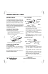
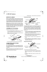
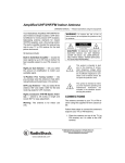
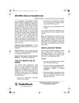
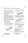
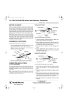
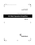
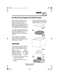
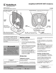
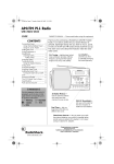
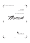
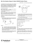
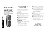
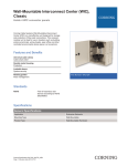
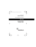
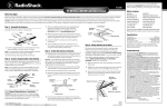
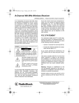
15-2153.fm Page 1 Wednesday, April 26, 2000 8:11 PM
VU-110XR VHF/UHF/FM Antenna with Matching Transformer
OWNER’S MANUAL — Please read before using this equipment.
Your RadioShack VHF/UHF/FM Antenna performs better than
standard antennas because of its special design features.
UHF Bowtie — delivers more of the UHF signal to your TV.
Since UHF signals are more difficult to receive than VHF signals, this antenna gives UHF signals the extra boost they need.
VHF/UHF Isolation Network — prevents the two types of TV
signals from interfering with each other. This results in cleaner
signals and a better picture on your TV.
UHF/VHF
Isolation Network
UHF Bowtie
Lead-In Terminal
Note: Both sections of the UHF/VHF isolation network
should remain parallel to the main boom.
CONNECTING LEAD-IN CABLE
TO THE ANTENNA
BEFORE YOU BEGIN
Before you begin installation, read this manual and the separate Consumer Product Safety Commission information sheet.
For your safety and convenience, plan each step of the installation and purchase the necessary hardware in advance. The
hardware required and the order in which you perform the steps
depend on the mounting and connection method you choose.
Warning: When you install your antenna, use extreme caution.
If the antenna starts to fall, let it go! It could contact overhead
power lines. If the antenna touches the power line, contact with
the antenna, mast, cable, or guy wires can cause electrocution
and death. Call the power company to remove the antenna. Do
not attempt to remove it yourself.
We recommend RG-6 cable and, if you prepare your own cable, a quality F-connector. You can also use 300-ohm flat, twinlead cable. (RadioShack carries a variety of suitable cables and
connectors.)
Note: If you prepare your own coaxial cable, be sure to slide
the supplied matching transformer’s weather boot onto the cable before you attach the F-connector.
Using Coaxial Cable
Main
Boom
Lead-In Terminal
Spade Terminal
ASSEMBLING THE ANTENNA
Strain-Relief Tab
Assemble the entire antenna on the ground.
Spade Terminal
Matching Transformer
1. Use the supplied hardware to loosely attach the supplied
mast clamp assembly to the main boom, as shown.
Lead-In Terminal
F-Connector
Flat Washers
Note: To access the mast clamp holes, move the antenna’s
elements out of the way as needed.
U-Bolt
Weather Boot
Large Wing Nuts
To connect coaxial cable to your antenna:
Mast Clamp
1. Thread the supplied matching transformer’s spade terminals through the antenna’s strain-relief tab.
2. Slide the spade terminals around the antenna’s lead-in terminals (on both sides of the boom), then secure them with
the supplied flat washers and large wing nuts.
Main Boom
Backup Plate
Lock Nuts
3. Screw the cable’s F-connector onto the matching transformer.
2. Press the supplied large end plugs into the main boom.
3. Pull the UHF bowtie’s two halves away from the main boom
until they lock into place. Then slide each half’s unattached
end over one of the antenna’s lead-in terminals (one for
each half of the UHF bowtie on each side of the boom).
4. Slip the weather boot over the connection. If you use a
rebuilt cable without a weather boot, cover the connection
with weather-resistant tape.
© 1998, 2000 Tandy Corporation.
All Rights Reserved.
RadioShack is a registered trademark used by Tandy Corporation.
RadioShack.com is a trademark used by Tandy Corporation.
15-2153.fm Page 2 Wednesday, April 26, 2000 8:11 PM
Using Twin-Lead Cable
5. Insert the top and bottom wing booms into the wing boom
brackets. Secure them with the four supplied 11/4-inch
screws and small wing nuts, as shown.
Main
Boom
Top Wing Boom
Wing Boom
Brackets
Lead-In Terminal
Twin-Lead Cable
11/4-Inch
Screws
Lead-In Terminal
Small Wing Nuts
Flat Washers
Strain-Relief Tab
Large Wing Nuts
Bottom Wing Boom
To connect flat, twin-lead cable to your antenna:
ATTACHING TO THE MAST
1. Split one end of the twin-lead cable for a length of about 3
inches. Then strip about 1/2 inch of insulation from both
leads.
We recommend that you enlist the help of another person before you put up the mast or attach your antenna to it. How you
set up your mast depends on your specific installation. Refer to
the separate Consumer Product Safety Commission information sheet for recommended methods.
2. Thread the stripped leads through the antenna’s strainrelief tab.
3. Wrap each lead around one of the antenna’s lead-in terminals (on both sides of the boom). Be sure there is enough
slack between the strain-relief tab and the antenna terminals to prevent stress on the cable or the terminals.
1. Slide the antenna’s mast clamp assembly over the end of
the mast.
2. Tighten the mast clamp assembly’s lock nuts to hold the
antenna in place. Do not overtighten the lock nuts.
4. Secure the leads with the supplied flat washers and large
wing nuts.
Caution: The crossover wires must not touch the antenna
boom, the mast, or each other. If necessary, carefully bend
the crossover wires to provide at least 1/2 inch of clearance
between parts.
UNFOLDING THE ANTENNA’S ELEMENTS
1. Hold the main boom’s elements near the pivot points and
pull them away from the boom until they snap into the selflocking plastic support insulators.
Crossover Wires
Caution: To avoid damage to the elements, do not pull
them near their outer ends. Once the elements are locked
into position, do not attempt to unlock them. Doing so might
break the self-locking tabs.
2. Hold each wing boom and turn its elements until they snap
squarely into place (perpendicular to the boom).
3. Press the supplied small end plugs into the wing booms.
4. Bolt the triangular wing boom brackets onto the main boom
using the supplied 11/2-inch screw and small wing nut, as
shown.
3. Set up the mast, then rotate it so the antenna’s shorter elements point toward the broadcast antennas of the stations
you want to receive.
Wing Boom Elements
1
1 /2-Inch
Screw
Wing Boom
Brackets
Main Boom
Short Elements
Toward TV
Stations’
Antennas
Main Boom
Small Wing Nut
Mast
2
Main Boom Long Elements
15-2153.fm Page 3 Wednesday, April 26, 2000 8:11 PM
ROUTING THE CABLE TO YOUR
TV/VCR/FM RECEIVER
• Use a 75-ohm grounding block at the point where the coaxial cable enters the house. Read the Consumer Product
Safety Commission sheet for grounding instructions.
If you use coaxial cable:
• Use a wall-through lead-in tube (not supplied) to neatly
route the coaxial cable through walls.
• Use plastic tape or mast standoff insulators to secure the
coaxial cable to the mast at about 3-foot intervals. Continue
down the roof and the side of the house using roof and wall
standoff insulators.
If you use twin-lead cable:
• Be sure the twin-lead cable remains at least 4 inches away
from all metal surfaces.
• Use coaxial cable nail-in clips every few feet to secure the
cable between the mast and where the cable enters the
house.
• Use standoff insulators about every 4 feet. Twist the twinlead cable about three turns between standoff insulators.
• Read the separate Consumer Product Safety Commission
sheet for grounding instructions.
CONNECTING TO YOUR TV/VCR AND FM RECEIVER
Connect the antenna’s lead-in cable to your TV/VCR and FM receiver’s antenna terminals according to the type of cable you used.
RadioShack carries a variety of splitters. Choose one that best suits your needs. Below are some sample connections.
Make connections as shown if you have:
UHF
300 Ohm
VHF
75 Ohm
• Coaxial antenna lead-in
• Twin-lead UHF terminals
• Coaxial VHF terminal
To FM
Receiver
RadioShack
Splitter with 75-Ohm Input
Cat. No. 15-1252
• Twin-lead FM antenna terminals
Coaxial Lead-In
from Antenna
Make connections as shown if you have:
UHF
300 Ohm
VHF
300 Ohm
• Coaxial antenna lead-in
• Twin-lead UHF terminals
• Twin-lead VHF terminals
RadioShack
Transformer/Splitter
Cat. No. 15-1139
• Twin-lead FM antenna terminals
To FM
Receiver
Coaxial Lead-In
from Antenna
Make connections as shown if you have:
TV
VHF/UHF
To
FM Receiver
• Coaxial antenna lead-in
• Combined coaxial VHF/UHF terminal
• Coaxial FM antenna terminal
RadioShack
Hybrid Splitter/Combiner
Cat. No. 15-1141
Coaxial Lead-In
from Antenna
3
15-2153.fm Page 4 Wednesday, April 26, 2000 8:11 PM
Make connections as shown if you have:
UHF
300 Ohm
VHF
75 Ohm
• Twin-lead antenna lead-in
• Twin-lead UHF terminals
• Coaxial VHF terminal
• Twin-lead FM antenna terminals
RadioShack
Splitter with 300-Ohm Input
Cat. No. 15-1251
To FM
Receiver
Twin-Lead Lead-In
from Antenna
Limited Ninety-Day Warranty
This product is warranted by RadioShack against manufacturing defects in material and workmanship under normal use for ninety (90) days from the date of purchase from RadioShack companyowned stores and authorized RadioShack franchisees and dealers. EXCEPT AS PROVIDED
HEREIN, RadioShack MAKES NO EXPRESS WARRANTIES AND ANY IMPLIED WARRANTIES,
INCLUDING THOSE OF MERCHANTABILITY AND FITNESS FOR A PARTICULAR PURPOSE,
ARE LIMITED IN DURATION TO THE DURATION OF THE WRITTEN LIMITED WARRANTIES
CONTAINED HEREIN. EXCEPT AS PROVIDED HEREIN, RadioShack SHALL HAVE NO LIABILITY OR RESPONSIBILITY TO CUSTOMER OR ANY OTHER PERSON OR ENTITY WITH RESPECT TO ANY LIABILITY, LOSS OR DAMAGE CAUSED DIRECTLY OR INDIRECTLY BY USE
OR PERFORMANCE OF THE PRODUCT OR ARISING OUT OF ANY BREACH OF THIS WARRANTY, INCLUDING, BUT NOT LIMITED TO, ANY DAMAGES RESULTING FROM INCONVENIENCE, LOSS OF TIME, DATA, PROPERTY, REVENUE, OR PROFIT OR ANY INDIRECT,
SPECIAL, INCIDENTAL, OR CONSEQUENTIAL DAMAGES, EVEN IF RadioShack HAS BEEN ADVISED OF THE POSSIBILITY OF SUCH DAMAGES.
Some states do not allow limitations on how long an implied warranty lasts or the exclusion or limitation of incidental or consequential damages, so the above limitations or exclusions may not apply to
you.
In the event of a product defect during the warranty period, take the product and the RadioShack
sales receipt as proof of purchase date to any RadioShack store. RadioShack will, at its option, unless otherwise provided by law: (a) correct the defect by product repair without charge for parts and
labor; (b) replace the product with one of the same or similar design; or (c) refund the purchase
price. All replaced parts and products, and products on which a refund is made, become the property of RadioShack. New or reconditioned parts and products may be used in the performance of
warranty service. Repaired or replaced parts and products are warranted for the remainder of the
original warranty period. You will be charged for repair or replacement of the product made after the
expiration of the warranty period.
This warranty does not cover: (a) damage or failure caused by or attributable to acts of God, abuse,
accident, misuse, improper or abnormal usage, failure to follow instructions, improper installation or
maintenance, alteration, lightning or other incidence of excess voltage or current; (b) any repairs
other than those provided by a RadioShack Authorized Service Facility; (c) consumables such as
fuses or batteries; (d) cosmetic damage; (e) transportation, shipping or insurance costs; or (f) costs
of product removal, installation, set-up service adjustment or reinstallation.
This warranty gives you specific legal rights, and you may also have other rights which vary from
state to state.
RadioShack Customer Relations, 200 Taylor Street, 6th Floor, Fort Worth, TX 76102
We Service What We Sell
RadioShack
A Division of Tandy Corporation
Fort Worth, Texas 76102
12/99
15-2153
04/00
Printed in the USA