1
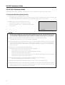
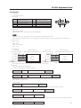
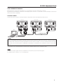
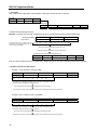
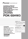
PDP-504CMX
Plasma Display Panel
RS-232C Commands
COMMAND PROTOCOL MANUAL
Manual Version 1.00
November 3, 2004
Pioneer Corporation
Pioneer Electronics (USA) Inc.
Industrial Solutions Business Group
This manual is copyrighted with all rights reserved. No part of this document may be reprinted, produced,
translated or utilized in any form or by any means now known or hereafter invented including, but not
limited to, any electronic, mechanical, photocopying and recording or information storage and retrieval
system means, without the express written permission from Pioneer Electronics (USA) Inc.
Every effort has been made to ensure that the information in this manual is accurate. Pioneer is not
responsible for printing or clerical errors.
Information in this document is subject to change without notice.
Copyright (c) 2004 Pioneer Electronics (USA) Inc.
Document No. PDP504CMX_RS232C-CPM
Printed in the United States of America.
Mention of third-party products is for informational purposes only and contributes neither an endorsement
nor a recommendation. Pioneer assumes no responsibility with regard to the performance or use of these
products.
No investigation has been made of common-law trademark rights in any word. Words that are known to
have current registrations are shown with an initial capital. Many, if not all, hardware and/or software
products referenced in this manual are identified by their trade names. Most, if not all, of these
designations are claimed a legally protected trademarks by the companies that make the product. It is not
Pioneer's intent to use any of these names generically and cautions the reader to investigate any claimed
trademark before using it for any purpose other than to refer to the product to which the trademark is
attached.
Pioneer makes no warranty of any kind, expressed or implied, about the contents of this manual, the
merchantability of the product or the product's fitness for any particular purpose.
Every precaution has been taken in the preparation of this manual. Although we tried to thoroughly check
that all instructions and information in this manual are accurate and correct, Pioneer can not be and is not
responsible, in whole or in part, for any damage or loss to your data and/or equipment that results from
your use of this document or from any information contained herein including, but not limited to, any
errors, omissions or typos that may have resulted in an incorrect operation or installation.
RS-232C Adjustment Mode
5.5 RS-232C Adjustment Mode
This display has a RS-232C terminal. It is possible to use a PC to make various adjustments and settings.
5.5.1 About the RS-232C Adjustment Mode
1) Adjustments in the RS-232C adjustment mode:
• The adjustments are written to the same memory area as for the integrator mode (refer to section 5.4.4,
‘PICTURE, White Balance and SCREEN Position Adjustment Values Memory Area Tables’).
2) Display screen in the RS-232C adjustment mode:
––
1 2 8 0 X 1 0 2 4@6 0
• The screen is as shown in the figure on the right.
The set ID is display in the ‘– –’ area at the upper left part
of the screen.
AD J U S T ME N T
Notes
(1) Always assign an ID before using the RS-232C adjustment mode. Also, include the ID for the set
to be controlled or adjusted in the RS-232C command. For details, refer to section 5.5.2, ‘Interface’.
(2) There are some RS-232C commands that can be used in the normal-operation mode.
For details refer to section, 5.5.5, ‘List of RS-232C Commands’.
(3) Of the adjustment values and setting items set by RS-232C commands, there are some items that are
stored in memory and some that are not. For details, refer to section 5.5.5, ‘List of RS-232C Commands’.
Also, when storing values in last memory, the conditions described in section 5.1.5, ‘Last Memory’,
must be satisfied.
(4) <DIN>/<DIY> (OSD display disable/enable setting)
Regardless of the setting, the following items can be displayed.
• Menu display (menu mode, integrator mode)
• Warnings before Auto Power OFF or Power Management operation
• Warning of high temperature inside the set
• Display announcing that the FUNCTIONAL LOCK is set, and the FUNCTIONAL LOCK setting display
• Display call (including holding a button down)
(5) The RS-232C adjustment mode is automatically cancelled in the following cases:
• When the [STANDBY/ON] or [MENU] button is pressed
(6) Before entering the RS-232C adjustment mode, be sure to cancel the integrator mode.
(6) When performing control using the RS-232C commands, not only control the input signal, but also be
sure to control the power. If the power is ON when there is no signal, the display continues to have a
weak discharge, which could affect the life of the display.
1
RS-232C Adjustment Mode
5.5.2 Interface
1) Connector
D-sub 9 pins (male)
2) Pin layout
Pin No.
1
2
3
4
5
1
Signal
NC (not connected)
TxD (Transmit Data)
RxD (Receive Data)
NC (not connected)
GND
Pin No.
6
7
8
9
5
Signal
NC (not connected)
NC (not connected)
RTS (Request To Send)
NC (not connected)
6
9
3) Baud Rate
9600 bps (standard)
(switch-able to 1200, 2400, 4800, 19200, 38400 bps)
Note
The baud rate of this display should be set to match the baud rate of the PC.
Also, when the RS-232C cable is to be extended over a long distance, a slower baud rate is recommended.
4) Data format
Start: 1 bit
Data: 8 bit
Parity: 0 (no parity)
Stop: 1 bit
5) Connection
Control PC
(with D25 serial port )
RXD 3
TXD 2
CTS 5
Plasma Display
(PDP-504CMX/50MXE1/50MXE1-S)
2
3
2
GND 7
Control PC
(with D9 serial port)
2 TXD
RXD 2
3 RXD
8 RTS
TXD 3
CTS 8
5 GND
GND 5
* D-sub 9-pin/D-sub 25-pin conversion tables are now available on the market.
Plasma Display
(PDP-504CMX/50MXE1/50MXE1-S)
2
3
2
2 TXD
3 RXD
8 RTS
5 GND
Straight Cable
6) Protocol
From the computer to the display
(1) When sending one command at a time:
STX (02 hex)
ID (2 Byte)
COMMAND (3 Byte or 6 Byte)
ETX (03 hex)
(2) When numerical direct commands are possible:
STX (02 hex)
ID (2 Byte)
COMMAND (3 Byte)
ARGUMENT (3 Byte)
ETX (03 hex)
COMMAND: 3 Byte (ASCII)
ARGUMERNT: 3 Byte (ASCII)
(3) Echo back
STX (02 hex)
COMMAND (3 Byte or 6 Byte)
ETX (03 hex)
When the received command is a numerical direct effect command, numerical data is returned.
STX (02 hex)
COMMAND (3 Byte)
ARGUMENT (3 Byte)
ETX (03 hex)
When the received command is non-corresponding command, ‘ERR’ is returned.
STX (02 hex)
ERR (3 Byte)
ETX (03 hex)
When it is determined that the received command cannot be processed (when PON is received when the power
is already ON, etc.), ‘XXX’ is returned.
STX (02 hex)
XXX (3 Byte)
ETX (03 hex)
2
RS-232C Adjustment Mode
5.5.3 ID Assignment
After connecting to the PC, an ID is assigned. The ID is assigned from the PC.
Commands: <IDC> (ID CLEAR) ........ Clears the assigned ID
<IDS> (ID SET) ............. Assigns an ID
IDS is only effective when an ID is not assigned.
Also, IDs are set starting from the set closest to the PC.
Example: Case of 4 displays (Assigning IDs with the PC for the first time)
First, as shown in the example in the figure below, perform an RS-232C connection and combination connection.
(Refer to section 5.5.4, ‘Combination Connection’.)
PC
Set #1
±
ID = 01 OUT
Set #2
IN
ID = 02 OUT
Set #3
IN
ID = 03 OUT
Set #4
IN
ID = 04
RS-232C connection
Sent commands:
1 <∗∗AJY>
2 <01 IDS>
‘
3 <∗∗AJY>
4 <02 IDS>
‘
5 <∗∗AJY>
6 <03 IDS>
‘
7 <∗∗AJY>
8 <04 IDS>
By sending RS-232C commands in this order, it is possible to assign an ID for each set.
Sets for which an ID has been set can only receive commands with an ID attached. Attach an ID before sending a
command.
Characters that can be used for assigning an ID include, 0 - 9 and A - F (there is not distinction between upper case and
lower case alphabet characters).
An ∗ (asterisk) can be used as follows:
<∗∗IDC>: Clear the IDs assigned for all sets.
<∗1AJY>: Only a set for which the second digit is 1, enters the RS-232C adjustment mode.
<2∗IN1>: The input of only a set for which the first digit is 2 is set to INPUT1.
Precautions when assigning IDs
Sets that were connected after a set whose ID was cleared cannot be operated with RS-232C commands.
After performing setting as shown in the figure above, when <∗∗AJY> = <∗∗IDC> is performed, the IDs for all the sets
from Set #1 to Set #4 are cleared, and only the one set (Set #1) that is directly connected to the PC can be controlled.
Furthermore, by performing <∗∗AJY> = <01 IDS>, it becomes possible to control the second set (Set #2). By setting
IDs in the same way for the other sets, it becomes possible to control the sets connected in succession.
Note
When the IDs are set, and when one or both of the IDs before a command is sent from the PC is ∗, there is no echo
back. When sending more commands, wait 6 seconds before sending the next command.
Example) When ∗∗OOO and ∗1OOO or 1∗OOO (OOO is the command) are sent from the PC, operation is performed,
but there is no echo back.
3
RS-232C Adjustment Mode
5.5.4 Combination Connection
When performing control and adjustment, it is convenient to connect several sets to one PC.
By performing a combination connection and assigning IDs to the sets, it is possible to control and adjust several sets
at the same time or separately.
Connection method:
Connect the sets as shown in the figure below, and perform control and adjustment with the PC.
Second set
First set
IN
PC
OUT
COM BIN ATION
IN
RS-232 C
OUT
IN
RS-232 C
COM BIN ATION
OUT
IN
Third set
OUT
COM BIN ATION
RS-232 C
IN
OUT
Combination cable
Combination cable
Note
Only the combination IN terminal or RS-232C terminal can be used at the same time on one set. Connecting them at
the same time could cause erroneous operation or be the cause of trouble, so do not connect them at the same
time. Also, do not connect pair of combination IN terminals or combination OUT terminals. Doing so could cause
trouble.
It is possible to use a general-purpose mini DIN 6-pin (straight) cable for the combination cable.
Note
To output RS-232C signals from the combination OUT terminal, an ID must be assigned.
For details, refer to section, 5.5.3, ‘ID Assignment’.
4
RS-232C Adjustment Mode
Under the connection conditions shown below, operation using a combination cable is assured up to 16 sets.
Conditions: 1 Length of RS-232C cable connecting PC to PDP-504CMX/PDP-50MXE1/PDP-50MXE1-S: 5 m
2 Combination cable length: 5 m each
3 Wire specifications for linking cable: Mini Din 6-pin straight (7 strand cable)
For 1 strand, suitable for AWG28:
Cross-section area = 0.08 mm2
≠
7 strands × π r2 = 7 × 3.14 × 0.062 = 0.079 mm2 ≠ 0.08 mm2
PC
PDP-504CMX
PDP-50MXE1
PDP-50MXE1-S
RS-232C
1
5m
OUT
IN
2
OUT
Combination cable 5m
IN
3
OUT
IN
#
Note
For details on the number of displays that can be connected in series using the video OUT terminal (INPUT1, 4), refer to
section 2.3, ‘Part Names’.
5
RS-232C Adjustment Mode
5.5.5 List of RS-232C Commands
How to read this Table
• RS-232C adjustment validity : Indicates whether or not the RS-232C adjustment mode can be used.
• Normal validity
: Indicates whether or not the normal-operation mode can be used.
• Numerical direct validity
: When a number (3-digit number) is attached to the end of a command, the
command can directly set that adjustment value.
• ‡ or ¶: Valid, No mark: Invalid
(NOTE) ¶ values are not stored in the last memory.
Command name
Remarks
AJY (232C integrator) Display
RS-232C
Numerical
Normal
Adjustment
Direct
Validity
Validity
Validity
[A]
AJN
–
Terminates the 232C integrator adjustment mode.
AJY
ADJUST: ON
Starts the 232C integrator adjustment mode.
AMN
AUDIO MUTING: OFF
Turns OFF the audio mute.
AMY
AUDIO MUTING: ON
Turns ON the audio mute.
AST
AUTO SET UP
Executes AUTO SETUP.
BHI
B HIGH: ∗∗∗
Adjusts B. HIGH.
BLW
B LOW: ∗∗∗
Adjusts B. LOW.
BRA
BAUD RATE: #####-232C
Displays the current baud rate.
BRAS01
BAUD RATE: 1200-232C
Sets the UART setting to 232C (1200BPS).
BRAS02
BAUD RATE: 2400-232C
Sets the UART setting to 232C (2400BPS).
BRAS03
BAUD RATE: 4800-232C
Sets the UART setting to 232C (4800BPS).
BRAS04
BAUD RATE: 9600-232C
Sets the UART setting to 232C (9600BPS).
BRAS05
BAUD RATE: 19200-232C
Sets the UART setting to 232C (19200BPS).
BRAS06
BAUD RATE: 38400-232C
Sets the UART setting to 232C (38400BPS).
BRT
BRIGHTNESS: ∗∗∗
Adjusts the brightness.
BSL
B SIDE MASK LEVEL: ∗∗∗
Adjusts the BLUE side mask.
¶
¶
¶
¶
¶
¶
‡
[B]
‡
‡
¶
‡
‡
‡
‡
‡
‡
‡
‡
‡
‡
‡
‡
‡
‡
‡
‡
‡
¶
‡
‡
‡
‡
‡
‡
‡
‡
‡
‡
¶
‡
‡
‡
‡
¶
‡
‡
‡
‡
‡
‡
‡
‡
‡
‡
‡
‡
‡
‡
[C]
CFR
CLOCK: ∗∗∗
Adjusts the CLOCK (PLL frequency).
CGB
COLOR DETAIL BLUE: ∗∗∗
Adjusts color detail BLUE.
CGC
COLOR DETAIL CYAN: ∗∗∗
Adjusts color detail CIAN.
CGG
COLOR DETAIL GREEN: ∗∗∗
Adjusts color detail GREEN.
CGM
COLOR DETAIL MAGENTA: ∗∗∗
Adjusts color detail MAGENTA.
CGR
COLOR DETAIL RED: ∗∗∗
Adjusts color detail RED.
CGY
COLOR DETAIL YELLOW: ∗∗∗
Adjusts color detail YELLOW.
CLS
COLOR SYSTEM: #####
Displays the current color system.
CLSS01
COLOR SYSTEM: AUTO
Sets the color system to AUTO.
CLSS02
COLOR SYSTEM: NTSC
Sets the color system to NTSC.
CLSS03
COLOR SYSTEM: PAL
Sets the color system to PAL.
CLSS04
COLOR SYSTEM: SECAM
Sets the color system to SECAM.
CLSS05
COLOR SYSTEM: 4.43NTSC
Sets the color system to 4.43NTSC
CLSS06
COLOR SYSTEM: PAL M
Sets the color system to PAL M.
CLSS07
COLOR SYSTEM: PAL N
Sets the color system to PAL N.
CM1
COLOR MODE: NORMAL
Sets the color mode to NORMAL.
CM2
COLOR MODE: STUDIO
Sets the color mode to STUDIO.
CNT
CONTRAST: ∗∗∗
Adjusts the CONTRAST.
COF
COLOR OFF: ∗∗∗∗∗∗∗∗
Displays the current COLOR OFF setting.
COFS00
COLOR OFF: DISABLE
Disables COLOR OFF.
COFS01
COLOR OFF: ENABLE
Enables COLOR OFF.
COL
COLOR: ∗∗∗
Adjusts the COLOR.
CPH
PHASE: ∗∗∗
Adjusts the PHASE (PLL phase).
CTP
COLOR TEMP.: ∗∗∗∗∗∗∗∗
Displays the current COLOR TEMP.
CTPS01
COLOR TEMP.: LOW
Sets the COLOR TEMP. to LOW.
CTPS02
COLOR TEMP.: MID LOW
Sets the COLOR TEMP. to MID LOW.
CTPS03
COLOR TEMP.: MIDDLE
Sets the COLOR TEMP. to MIDDLE.
CTPS04
COLOR TEMP.: MID HIGH
Sets the COLOR TEMP. to MID HIGH.
CTPS05
COLOR TEMP.: HIGH
Sets the COLOR TEMP. to HIGH.
‡
‡
‡
‡
‡
6
RS-232C Adjustment Mode
Command name
AJY (232C integrator) Display
Remarks
CTR
CTI: ###
Displays the current CTI setting.
CTRS00
CTI: OFF
Sets CTI to OFF.
CTRS01
CTI: ON
Sets CTI to ON.
DIY
OSD: ON
Turns ON the OSD display.
DNR
DNR: ######
Displays the current DNR setting.
DNRS00
DNR: OFF
Sets digital NR to ON.
DNRS01
DNR: LOW
Sets digital NR to LOW.
DNRS02
DNR: MIDDLE
Sets digital NR to MIDDLE.
DNRS03
DNR: HIGH
Sets digital NR to HIGH.
DOF
–
Clears the currently displayed OSD display.
DPR
DPR
Resets the still image repeat function.
DW0
#
Reduces the adjustment value by 10.
DWn
#
Reduces the adjustment value by n (n = 1 to 9).
DWF
#
Sets the adjustment value to the minimum value.
ENH
H. ENHANCE: ∗∗∗
Adjusts H ENHANCE.
ENV
V. ENHANCE: ∗∗∗
Adjusts V ENHANCE.
ESV
ENERGY SAVE: ∗∗∗∗∗∗∗∗
Displays the current ENERGY SAVE setting.
ESVS00
ENERGY SAVE: STANDARD
Sets the ENERGY SAVE setting to STANDARD.
ESVS01
ENERGY SAVE: MODE1
Sets the ENERGY SAVE setting to MODE 1 (energy saving).
ESVS02
ENERGY SAVE: MODE2
Sets the ENERGY SAVE setting to MODE 2 (energy saving).
ESVS03
ENERGY SAVE: MODE3
Sets the ENERGY SAVE setting to MODE 3 (long life).
ESVS04
ENERGY SAVE: AUTO
Sets the ENERGY SAVE setting to AUTO.
RS-232C
Numerical
Normal
Adjustment
Direct
Validity
Validity
Validity
¶
‡
‡
[D]
DIN
Turns OFF the OSD display.
‡
‡
¶
‡
‡
‡
‡
‡
‡
‡
‡
‡
‡
‡
‡
‡
‡
‡
‡
[E]
‡
‡
¶
‡
‡
‡
‡
‡
‡
‡
[F]
FCA
FAN: AUTO
Sets the fan rpm control to AUTO.
FCL
#########
Displays the current FUNCTIONAL LOCK setting.
FCLS00
LOCK OFF
Clears the FUNCTIONAL LOCK.
FCLS01
BUTTONS LOCK
Inhibits the main-control panel button control.
FCLS02
IR LOCK
Inhibits remote-control button control.
FCLS03
BUTTONS&IR LOCK
Inhibits both main-control panel and remote-control button control.
FCLS04
MEMORY LOCK
Sets the MEMORY LOCK.
FCM
FAN: MAX
Sets the fan rpm control to maximum.
FDT
FUNCTION DEFAULT
Executes FUCNTION DEFAULT.
FMK
SCREEN MASK: #####
Displays the current SCREEN MASK setting.
FMKS00
SCREEN MASK: OFF
Sets the SCREEN MASK to OFF.
FMKS02
SCREEN MASK: INVERSE
Sets the SCREEN MASK to INVERSE (negative-positive inversion).
FMKS03
SCREEN MASK: WHITE
Turns ON the WHITE mask.
FMKS04
SCREEN MASK: RED
Turns ON the RED mask.
FMKS05
SCREEN MASK: GREEN
Turns ON the GREEN mask.
FMKS06
SCREEN MASK: BLUE
Turns ON the BLUE mask.
FMKS07
SCREEN MASK: YELLOW
Turns ON the YELLOW mask.
FRC
FRC: #####
Displays the current FRC setting.
FRCS01
FRC: MODE1
Sets FRC to MODE 1.
FRCS02
FRC: MODE2
Sets FRC to MODE 2.
FRCS03
FRC: MODE3
Sets FRC to MODE 3.
FRP
FRESH POSITION
Initializes the integrator and SCREEN adjustment values.
FXO
AUDIO OUT: FIX
Selects fixed audio output.
[G]
## GET commands are valid in any state including STB (except for [GPI], [GPS], [GSS], [GWB]).
GHI
G HIGH: ∗∗∗
Adjusts G HIGH.
GLW
G LOW: ∗∗∗
Adjusts G LOW.
GPI
(GET PICTURE DATA)
Gets integrator PICTURE data.
GPS
(GET POSITION DATA)
Gets integrator SCREEN data.
7
‡
¶
‡
‡
‡
‡
‡
‡
¶
¶
‡
‡
‡
‡
‡
‡
‡
¶
‡
‡
‡
‡
‡
‡
‡
¶
¶
¶
¶
‡
‡
RS-232C Adjustment Mode
Command name
Remarks
AJY (232C integrator) Display
GRA
GRADATION: #######
Displays the current GRADATION setting
GRAS01
GRADATION: GAMMA 2.0
Sets GRADATION to ‘GAMMA 2.0’.
GRAS02
GRADATION: GAMMA 1.8
Sets GRADATION to ‘GAMMA 1.8’.
GRAS03
GRADATION: GAMMA 2.2
Sets GRADATION to ‘GAMMA 2.2’.
GRAS04
GRADATION: DRE MID
Sets GRADATION to ‘DRE MID’.
GRAS05
GRADATION: DRE HIGH
Sets GRADATION to ‘DRE HIGH’.
GRAS06
GRADATION: DRE LOW
Sets GRADATION to ‘DRE LOW’.
GRAS07
GRADATION: HIGH CNT.
Sets GRADATION to ‘HIGH CONTRAST’.
GSL
G SIDE MASK LEVEL: ∗∗∗
Adjusts the GREEN side mask.
GSO
(GET STATUS OPTIONDATA)
Gets OPTION data.
GSS
(GET STATUS SETUP DATA)
Gets SETUP data.
GST
(GET STATUS)
Gets STATUS.
GWB
(GET WHITE BAL.DATA)
Gets integrator WHITE BALANCE data.
HPS
H. POSITION: ∗∗∗
Adjusts the HORIZONTAL POSITION.
HSI
H. SIZE:∗∗∗
Adjusts the HORIZONTAL SIZE.
IDC
ID CLEAR
Clears the ID.
DS
ID No.: ∗∗
Sets the ID.
IN1
INPUT1
Switches the main screen to INPUT1.
IN2
INPUT2
Switches the main screen to INPUT2.
IN3
INPUT3
Switches the main screen to INPUT3.
IN4
INPUT4
Switches the main screen to INPUT4.
IN5
INPUT5
Switches the main screen to INPUT5.
INP
INPUT#
Displays the current input function for the main screen.
INPS01
INPUT1
Switches the main screen to INPUT1.
INPS02
INPUT2
Switches the main screen to INPUT2.
INPS03
INPUT3
Switches the main screen to INPUT3.
INPS04
INPUT4
Switches the main screen to INPUT4.
INPS05
INPUT5
Switches the main screen to INPUT5.
RS-232C
Numerical
Normal
Adjustment
Direct
Validity
Validity
Validity
¶
‡
‡
‡
‡
‡
‡
‡
‡
¶
¶
¶
¶
¶
¶
¶
¶
‡
[H]
‡
‡
‡
‡
[I]
‡
‡
‡
‡
‡
‡
‡
¶
‡
‡
‡
‡
‡
‡
‡
‡
‡
‡
¶
‡
‡
‡
‡
‡
‡
‡
‡
‡
‡
‡
‡
[L]
LEN
FRONT INDICATOR: OFF
Turns OFF the front indicator.
LEY
FRONT INDICATOR: ON
Turns ON the front indicator.
LNN
LOUDNESS: OFF
Disables LOUDNESS.
LNY
LOUDNESS: ON
Enables LOUDNESS.
MCD
COLOR DECODING: ∗∗∗∗∗∗
Displays the current COLOR DECODING.
MCDS01
COLOR DECODING: RGB
Sets COLOR DECODING to RGB (VIDEO).
MCDS02
COLOR DECODING: COMPONENT1
Sets COLOR DECODING to COMPONENT1 (Y CbCr).
MCDS03
COLOR DECODING: COMPONENT2
Sets COLOR DECODING to COMPONENT2 (Y PbPr).
MCN
MASK CONTROL: OFF
Turns OFF MASK CONTROL.
MCY
MASK CONTROL: ON
Turns ON MASK CONTROL.
MGF
#############
Displays the 2 x 2 ON/OFF status.
MGFS00
2 x 2: OFF
Turns OFF 2 x 2 (4-screen multi).
MGFS01
2 x 2: ON
Turns ON 2 x 2 (4-screen multi).
MGP
#############
Displays the current 2 x 2 seam-consideration/magnification position.
MGPS01
2 x 2 NORMAL UP LEFT
Sets 2 x 2 to upper left (no seam consideration).
MGPS02
2 x 2 NORMAL DOWN LEFT
Sets 2 x 2 to lower left (no seam consideration).
MGPS03
2 x 2 NORMAL UP RIGHT
Sets 2 x 2 to upper right (no seam consideration).
MGPS04
2 x 2 NORMAL DOWN RIGHT
Sets 2 x 2 to lower right (no seam consideration).
MGPS05
2 x 2 ADJUSTED UP LEFT
Sets 2 x 2 to upper left (seam consideration).
MGPS06
2 x 2 ADJUSTED DOWN LEFT
Sets 2 x 2 to lower left (seam consideration).
MGPS07
2 x 2 ADJUSTED UP RIGHT
Sets 2 x 2 to upper right (seam consideration).
MGPS08
2 x 2 ADJUSTED DOWN RIGHT
Sets 2 x 2 to lower right (seam consideration).
[M]
¶
‡
‡
‡
‡
‡
¶
‡
‡
¶
‡
‡
‡
‡
‡
‡
‡
‡
¶
‡
‡
8
RS-232C Adjustment Mode
Command name
Remarks
AJY (232C integrator) Display
MIR
MIRROR MODE: ###
Displays the current MIRROR MODE setting.
MIRS00
MIRROR MODE: OFF
Turns the MIRROR MODE OFF (normal display).
MIRS01
MIRROR MODE: X
Sets the MIRROR MODE to left-right reversal.
MIRS02
MIRROR MODE: Y
Sets the MIRROR MODE to up-down reversal.
MIRS03
MIRROR MODE: XY
Sets the MIRROR MODE to up-down, left-right reversal.
MNR
MPEG NR: ######
Displays the current MPEG NR setting.
MNRS00
MPEG NR: OFF
Turns MPEG NR OFF.
MNRS01
MPEG NR: LOW
Sets MPEG NR to LOW.
MNRS02
MPEG NR: MIDDLE
Sets MPEG NR to MIDDLE.
MNRS03
MPEG NR: HIGH
Sets MPEG NR to HIGH.
MSC
###########
Displays 2-screen display operation ON/OFF.
MSCS00
MULTISCREEN: OFF
Turns the 2-screen display operation OFF.
MSCS01
MULTISCREEN: ON
Turns the 2-screen display operation ON.
MST
###########
Displays the current 2-screen operation type.
MSTS01
2SCREEN
Sets 2-screen operation to 2 SCREEN.
MSTS02
PinP DOWN RIGHT
Sets 2-screen operation to PinP (lower right).
MSTS03
PinP UP RIGHT
Sets 2-screen operation to PinP (upper right).
MSTS04
PinP UP LEFT
Sets 2-screen operation to PinP (upper left).
MSTS05
PinP DOWN LEFT
Sets 2-screen operation to PinP (lower left).
MSTS06
PoutP
Sets 2-screen operation to PoutP.
MTN
VIDEO MUTING: OFF
Turns OFF video muting.
MTY
VIDEO MUTING: ON
Turns ON video muting.
RS-232C
Numerical
Normal
Adjustment
Direct
Validity
Validity
Validity
¶
‡
‡
‡
‡
¶
‡
‡
‡
‡
¶
‡
‡
¶
‡
‡
‡
‡
‡
‡
¶
¶
¶
‡
‡
¶
‡
‡
‡
‡
‡
‡
¶
¶
[O]
OMN
ORBITER: OFF
Turns ORBITER OFF.
OMY
ORBITER: ON
Turns ORBITER ON.
‡
‡
[P]
PLN
BRIGHT ENHANCE: OFF
Turns the center brightness enhancement OFF.
PLY
BRIGHT ENHANCE: ON
Turns the center brightness enhancement ON.
POF
–
Power OFF
PON
–
Power ON
PUC
PURECINEMA: ######
Displays the current PURECINEMA setting.
PUCS00
PURECINEMA: OFF
Turns PURECINEMA OFF.
PUCS01
PURECINEMA: STANDARD
Sets PURECINEMA to STANDARD.
PUCS02
PURECINEMA: ADVANCE
Sets PURECINEMA to ADVANCED.
RHI
R HIGH: ∗∗∗
Adjusts R. HIGH.
RLW
R LOW: ∗∗∗
Adjusts R. LOW.
RSL
R SIDE MASK LEVEL: ∗∗∗
Adjusts the RED side mask.
‡
‡
‡
¶
‡
‡
‡
‡
‡
[R]
‡
‡
‡
‡
‡
‡
[S]
SFT
SIGNAL FORMAT: ####
Displays the current SIGNAL FORMAT.
SFTS01
SIGNAL FORMAT:
Sets the SIGNAL FORMAT to PC FORMAT 1
VGAorXGAorSXGAor720PC
(VGA or XGA or SXGA or 720PC).
SFTS02
SIGNAL FORMAT:
Sets the SIGNAL FORMAT to PC FORMAT 2
WVGAorWXGAorSXGA+
(WVGA or WXGA or SXGA+).
SIGNAL FORMAT:
Sets the SIGNAL FORMAT to VIDEO 525p or VIDEO 750p.
SFTS03
¶
‡
‡
‡
VIDEO 525p or VIDEO 750p
SFTS04
SIGNAL FORMAT: PC AUTO
Sets the SIGNAL FORMAT to PC AUTO.
SHP
SHARPNESS: ∗∗∗
Adjusts the SHARPNESS.
SIM
SIDE MASK MODE: ######
Displays the current side mask setting.
SIMS01
SIDE MASK MODE: NORMAL
Sets the side mask setting to normal.
SIMS02
SIDE MASK MODE: OVERLAY1
Sets the side mask setting to OVERLAY1.
SIMS03
SIDE MASK MODE: OVERLAY2
Sets the side mask setting to OVERLAY2.
SLN
–
Turns the STILL setting to OFF.
SLY
STILL
Turns the STILL setting to ON.
9
‡
‡
¶
‡
‡
‡
‡
‡
‡
RS-232C Adjustment Mode
Command name
AJY (232C integrator) Display
Remarks
SSI
#########
Displays the current sub screen input function.
SSIS01
INPUT1(SUB)
Switches the sub screen to INPUT1.
SSIS02
INPUT2(SUB)
Switches the sub screen to INPUT2.
SSIS03
INPUT3(SUB)
Switches the sub screen to INPUT3.
SSIS04
INPUT4(SUB)
Switches the sub screen to INPUT4.
SSIS05
INPUT5(SUB)
Switches the sub screen to INPUT5.
STD
STANDARD W/B
Returns the integrator PICTURE and WHITE
RS-232C
Numerical
Normal
Adjustment
Direct
Validity
Validity
Validity
¶
‡
‡
‡
‡
‡
‡
¶
‡
‡
‡
‡
‡
BALANCE to the factory settings.
SVL
SUB VOLUME: ∗∗∗
Adjusts the sub volume.
SZM
########
Displays the current screen size setting.
SZMS00
Dot by Dot or PARTIAL
Sets the screen size to Dot by Dot or PARTIAL.
SZMS01
4:3
Sets the screen size to 4:3.
SZMS02
FULL or FULL1080i
Sets the screen size to FULL or FULL1080i.
SZMS03
ZOOM
Sets the screen size to ZOOM.
SZMS04
CINEMA
Sets the screen size to CINEMA.
SZMS05
WIDE
Sets the screen size to WIDE.
SZMS08
FULL1035i
Sets the screen size to FULL1035i.
SZMS09
UNDERSCAN
Sets the screen size to UNDERSCAN.
‡
¶
‡
‡
‡
‡
‡
‡
‡
‡
TINT: ∗∗∗
Adjusts the TINT.
‡
UP0
#
Adds 10 to the adjustment value.
UPn
#
Adds n to the adjustment value (n = 1 to 9).
¶
‡
‡
‡
‡
‡
‡
‡
‡
[T]
TNT
‡
[U]
UPF
#
Sets the adjustment value to maximum.
USC
UNDERSCAN: ∗∗∗
Displays the current UNDERSCAN setting.
USCS00
UNDERSCAN: OFF
Turns the UNDERSCAN setting OFF.
USCS01
UNDERSCAN: ON
Turns the UNDERSCAN setting ON.
‡
‡
‡
‡
‡
‡
‡
‡
‡
‡
‡
‡
‡
‡
[V]
VOL
VOLUME: ∗∗∗
Adjusts the audio volume.
VPS
V. POSITION: ∗∗∗
Adjusts the V POSITION.
VRO
AUDIO OUT VARIABLE
Selects variable audio output.
VSI
V. SIZE: ∗∗∗
Adjusts V. SIZE.
‡
‡
‡
10
RS-232C Adjustment Mode
5.5.6 GET Commands
What are GET commands?
• They are commands for outputting TXD such as adjustment data from the internal microcomputer of the plasma
display to a PC.
• Adjustment data and the like is output in ASCII code.
Note Command names are given inside brackets < >.
• Data output format
STX (02hex)
Data
Data
····
Data
Checksum
ETX (03hex)
Notes
• A GET command is invalid when no ID No. is assigned to the set.
• A GET command is invalid when a wildcard (*) is used in the ID No. when sending the command.
1) <GST> (GET STATUS)
Order
Size
Remarks
1
2
3
4
Display data
Power data
Input function data (main)
Input function data (sub)
Data Contents
3 Byte
3 Byte
3 Byte
3 Byte
5
6
Screen size data
2-screen display
1 Byte
1 Byte
7
FUNCTIONAL LOCK data
1 Byte
8
9
10
11
12
13
14
15
Dummy data
Temperature data 2
Temperature data 3
Serial
Dummy data
Dummy data
HOURMETER
Check sum
3 Byte
3 Byte
3 Byte
15 Byte
3 Byte
3 Byte
5 Byte
2 Byte
See below
See below (The third character is sub input.)
Input data when GST is received (INPUT1 to 5 is displayed as IN1 to 5.)
Sub input data when GST is received Note 3)
(INPUT 1 to 5 is displayed as IS1 to IS5.)
See below
0: OFF (1 screen)
1: 2-SCREEN
2: PinP (lower right)
3: PinP (upper right) 4: PinP (upper left) 5: PinP (lower left)
6: PoutP
0: LOCK OFF 1: BUTTONS LOCK 2: IR LOCK
3: IR&BUTTONS LOCK 4: MEMORY LOCK
(3-digit number)
(Internal temperature: Reference value) °C Note 1)
(External temperature: Reference value) °C Note 1)
Display data
Power data
Screen size data
(3-digit number)
Displays the time.
First character
Second character
Third character
First character
Second character
Generation data: 4 (fixed)
Inch data: 4 (43 inch), 5 (50 inch)
Destination data: M (fixed)
Power state & signal state
PN (POWER ON & normal signal input)
PL (POWER ON & no input)
PO (POWER ON & OUT OF RANGE signal input)
SN (Normal standby)
SW (Standby by POWER MANAGMENT)
SS (Standby by SD or PD)
Third character Sub input signal state during multi-screen display Note 2)
N (Normal signal input) L (No input)
O (OUT OF RANGE signal input)
First character 0; Dot by Dot or PARTIAL 1; 4 : 3 2; FULL or FULL1080i
3; ZOOM 4;CINEMA 5;WIDE 8;FULL1035i 9; UNDERSCAN
NOTE 1) During standby and immediately after POWER ON, the proper value is not output. In this case, wait a moment
after the POWER ON, then get the data. The temperature data is output as a reference (the values are not
guaranteed values). Normally, refer to temperature data 3.
NOTE 2) During standby and during 1-screen display, dummy data (symbol) is output.
NOTE 3) During standby and during 1-screen display the values stored in memory for the product are output.
11
RS-232C Adjustment Mode
2) <GPI> (GET PICTURE DATA: Gets integrator/PICTURE data.)
Order
1
2
3
4
5
6
7
8
9
10
11
12
13
14
15
16
Data contents
CONTRAST
BRIGHTNESS
C. DETAIL R (RED)
C. DETAIL Y (YELLOW)
C. DETAIL G (GREEN)
C. DETAIL C (CYAN)
C. DETAIL B (BLUE)
C. DETAIL M (MAGENTA)
H.ENHANCE
V.ENHANCE
COLOR
TINT
SHARPNESS
Input function data (main)
Screen size data
Check sum
Size
3 Byte
3 Byte
3 Byte
3 Byte
3 Byte
3 Byte
3 Byte
3 Byte
3 Byte
3 Byte
3 Byte
3 Byte
3 Byte
3 Byte
1 Byte
2 Byte
Remarks
#
#
#
#
#
#
#
#
Outputs dummy data for a video signal. #
Outputs dummy data for a video signal. #
Outputs dummy data for a PC signal. #
Outputs dummy data for a PC signal. #
Outputs dummy data for a PC signal. #
• 7 and 8 output the same contents as GST items 3 and 5.
• When the type of # signal is not set, dummy data is output.
3) <GWB> (GET WHITE BAL. DATA: Gets integrator/WHITE BAL. data.)
Order
1
2
3
4
5
6
7
8
9
Data contents
R.HIGH
G.HIGH
B.HIGH
R.LOW
G.LOW
B.LOW
Input function data (main)
Screen size data
Check sum
Size
3 Byte
3 Byte
3 Byte
3 Byte
3 Byte
3 Byte
3 Byte
1 Byte
2 Byte
Remarks
#
#
#
#
#
#
• 7 and 8 output the same contents as GST items 3 and 5.
• When the type of # signal is not set, dummy data is output.
4) <GPS> (GET POSITION DATA: Gets integrator/SCREEN data.)
Order
1
2
3
4
5
6
7
8
9
Data contents
H.POSITION
V.POSITION
Size
3 Byte
3 Byte
H.SIZE
V.SIZE
CLOCK
PHASE
Input function data (main)
Screen size data
Check sum
3 Byte
3 Byte
3 Byte
3 Byte
3 Byte
1 Byte
2 Byte
Remarks
#
#
#
#
Outputs dummy data for PC digital and Video signal. #
Outputs dummy data for PC digital and Video signal. #
• 7 and 8 output the same contents as GST items 3 and 5.
• When the type of # signal is not set, dummy data is output.
12
RS-232C Adjustment Mode
5) <GSS> (GET STATUS SETUP: Gets menu and integrator SETUP data.)
Order
Data contents
1
GRADATION
Size
1 Byte
2
3
4
BRT.ENHANCE
SUB VOLUME
COLOR TEMP.
1 Byte
2 Byte
1 Byte
5
DNR
1 Byte
6
MPEG NR
1 Byte
7
8
CTI
PURECINEMA
1 Byte
1 Byte
9
COLOR DECODING
1 Byte
10
COLOR SYSTEM
1 Byte
11
12
13
14
15
SIGNAL FORMAT
Dummy data
Input function data (main)
Screen size data
Check sum
3 Byte
3 Byte
3 Byte
1 Byte
2 Byte
SIGNAL FORMAT
Output
1: GAMMA 2.0 2: GAMMA 1.8
3: GAMMA 2.2 4: DRE MID
5: DRE HIGH
6: DRE LOW
7: HIGH CNT.
0: OFF 1: ON
00 to 20
1: LOW
2: MID LOW
3: MIDDLE 4: MID HIGH
5: HIGH
0: OFF
1: LOW
2: MIDDLE 3: HIGH
0: OFF
1: LOW
2: MIDDLE 3: HIGH
0: OFF 1: ON
0: OFF 1: STANDARD
2: ADVANCE
1: RGB 2: COMPONENT1
3: COMPONENT2
1: AUTO 2: NTSC 3: PAL
4: SECAM 5: 4.43NTSC
6: PAL M 7: PAL N
Remarks
#
#
#
#
#
#
#
#
#
# See below
S01 ............ VGA or XGA or SXGA or 720-PC
(720-PC can be selected only when a video card is mounted.)
S02 ............ WVGA or WXGA or SXGA+
S03 ............ 525p or 750p (Either one can be selected only when a video
card is mounted.) or PC AUTO
*** ............. Dummy data is output for signals other than those above.
• 13 and 14 output the same contents as GST items 3 and 5.
• Dummy data is output for setting data that cannot be output depending on the type of # signal.
13
RS-232C Adjustment Mode
6) <GSO> (GET STATUS OPTION: Gets menu and integrator OPTION data.)
Order Data contents
1
ENERGY SAVE
Size
1 Byte
2
3
4
5
ORBITER
MASK CONTROL
AUDIO OUT
SCREEN MASK
1 Byte
1 Byte
1 Byte
1 Byte
6
SIDE MASK MODE
1 Byte
7
8
9
10
11
R SIDE MASK LEVEL
G SIDE MASK LEVEL
B SIDE MASK LEVEL
2x2
2 x 2 LAYOUT & TYPE
3 Byte
3 Byte
3 Byte
1 Byte
1 Byte
12
13
14
15
16
17
18
19
MIRROR MODE
OSD
FRONT INDICATOR
FAN CONTROL
COLOR MODE
PRO USE UNDERSCAN
PRO USE COLOR OFF
FRC
1 Byte
1 Byte
1 Byte
1 Byte
1 Byte
1 Byte
1 Byte
1 Byte
20
21
22
23
Dummy data
Input function data (main)
Screen size data
Check sum
Total
3 Byte
3 Byte
1 Byte
2 Byte
34 Byte
Output
1: STANDARD 2: MODE 1
3: MODE 2
4: MODE 3
5: AUTO
0: OFF 1: ON
0: OFF 1: ON
1: FIXED 2: VARIABLE
0: OFF
2: INVERSE
3: WHITE
4: RED
5: GREEN
6: BLUE
7: YELLOW
1: NORMAL 2: OVERLAY1
3: OVERLAY2
000 to 255
000 to 255
000 to 255
0: OFF 1: ON
1: NORMAL&UP LEFT
2: NORMAL&DOWN LEFT
3: NORMAL&UP RIGHT
4: NORMAL&DOWN RIGHT
5: ADJUSTED&UP LEFT
6: ADJUSTED&DOWN LEFT
7: ADJUSTED&UP RIGHT
Remarks
8: ADJUSTED&DOWN RIGHT
0: OFF 1: X 2: Y 3: XY
0: OFF 1: ON
0: OFF 1: ON
1: AUTO
2: MAX
1: NORMAL 2: STUDIO
0: OFF 1: ON
0: DISABLE 1: ENABLE
1: MODE1 2: MODE2
3: MODE3
• 21 and 22 output the same contents as GST items 3 and 5.
14
RS-232C Adjustment Mode
Check Sum
This is data to which 2-Byte ASCII code is added to a data group returned by a GET command.
PC side
STX
02 (hex)
GET command
ID
2 Byte
ETX
03 (hex)
3 Byte
Set side
STX
02 (hex)
GET command
Check Sum
Data
*Byte
3 Byte
2 Byte
ETX
03 (hex)
A detailed example will be given below.
Example: The Check Sum value that is added when the GET command GAA returned the following 6-Byte data.
Data group (ASCII)
+ check sum
The data group is put in to binary code one
character at a time and displayed (only the
last two digits are displayed)
GET command
GAA
47
41
41
Data (6 Byte)
100128
31
30
30
Check Sum
xx (before calculation)
31
32
38
When these values are added the result is 1F8 (hex)
As the data format, F5 is converted to ASCII code and sent.
The following data is output from the plasma display side.
GET command
STX
02 (hex)
Data
100 (missing data) 28
GAA
Check Sum
F5
ETX
03 (hex)
Note: The returned data group will be in capital letters. Please keep this in mind when introducing it into the binary display.
Example of Check Sum applications
Example 1: when the data is missing one Byte
STX
02 (hex)
47
41
GET command
GAA
41
31
30
Data (6 Byte)
100 (missing data) 28
30
32
Check Sum
F5
ETX
03 (hex)
38
The data group is calculated according to the rules by a PC application and
when these values are added the result is 1C4 (hex).
Here, the check sum [F5 (hex)] and the calculated [C4 (hex)] do not match.
Since they do not match, the PC application sends the GET command again and gets the data again.
Example 2: when one Byte of data is unreadable
STX
02 (hex)
47
41
GET command
GAA
41
31
30
Data (6 Byte)
100328
33
30
32
Check Sum
F5
38
The data group is calculated according to the rules by a PC application and
when these values are added the result is 1F7 (hex).
Here, the check sum [F5 (hex)] and the calculated [F7 (hex)] do not match.
Since they do not match, the PC application sends the GET command again and gets the data again.
15
ETX
03 (hex)
PDP-504CMX
RS-232C Command Protocol Manual
Pioneer Electronics (USA) Inc.
Industrial Solutions Business Group
2265 East 220th Street
Long Beach, California 90810
United States of America
(310) 952-2000
http://www.pioneerelectronics.com