1
'r
3s=r--*-**
, t
t
*':*
o-si'
€I
-iiJ\
! l
:E*
.{F
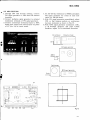
(0rrroruEen
AM
RECEIUER
/FN STEREO
s
450
HG
RFAssT AwE
(=
lE
oLN
0,o3
2SC+61
T
.Y1
(o
C!
5
a
c.l
cw
J
6
lu,Quz2SA?25 xz
ozor zo{2scl222xz
l0v
5
d
e
o
6
(o
F
(-)
9
o
,2
, ( q
d-
IK
{.
a
ql
-E
<!,
@
&
r
2SCt222
S WI T C H I S;
SI SPEAKER
S
1
P O WR
E OFF
2
S P A
3
SP OFF
Ss
MODE
+---_ l'10N0
STEREO
So
LOUDNESS
3
6
RFAsst AwE
Cr1.0.4'/:S
o,orHAlll3?
INO
STEREO
EV50mA
o
e
6l
C-)
:
2
E.
l--'.
I
o
.
o
l
d
J-P
i.iT;
H.;
'T=
iH
Cw\.41hs
I
:<
o
o
-'l
3
I
o
G
>
I
F+
o=-F
"5
n
:<
o
s
CW.
t .t
e
2SCl222
xz I
-t=fr
33.611
I
o ,
d
;q
tari-
F*
F
I
LO
6-
e
a
3l
?sct3
8+ D
I
)<,
a
'l nr t lr u
'
Qrot
-d
I
s
n4
H t
(-)
9,
N
q3or2503l3R
F
G.
+
d
@
e
01
C2a6C.OI
v)
C
VR l BALAN C E
CONTROL
1tl(85)
5
tr-
)
o
t
3-
--25.
h - A
Uxos ugot
DS-l50Ax+
DtAutt't0tCAT0R
8 V 3 0 0 m xA3
(DrrtoNEER"
ASs'y AWK- 009
eu,,Qzor
2scIgtgn" itAtiba',
0
E
CJ
13Rx+
-
.--r* t
o
,PLS
9
6
s'hF
@@eo
I
nJ
I
o
&.,
o
E
o l
=
ADilusrHEN-r
c?or22P
+
(1/2w)
ft4s)o(r/2w,_|.a @O
@@
|
I
q J t
E
oros,ezoe
25 Cl tltl 5At-4;
L2 14H
o
o
=
Cmz. Crro
lr
a-a+
P
E
>
^+a
21t++
{,4s
=
:s
5
9
o
,
-+'
)cD
9.
> 9
d
t
r"5
.T
tO! 2 xz
2SCl38/|. Dror,ft12
Qror
Rlor
33 93_orFU
ocor250313R
3
c\r
O
.<r-
U)
C
5
)
c
o
r
-
c!-
n
n
UXos- UIOB
DIAL INDICATOR
E V3 0 0 m xA3
trr.vl
n
U3o8
ADJUSTI'IENT
l0 (llZWl
Rzoo
A S s ' y AWK - 069
Qo,r,Qos
2SCl3tSAxz 2g\ltQlxz
,0.6V
SW 3H a1
Rll E2K
=
=
.--* t
.s
a
ADJUSTilENT
c?os22P
+
cE.
$
o
o
E
=
Crn22PdADilUSTtlENT
L2 11H
-o
shs'1i++
I
o
E
>
Sfvcn
O.
-+'
> 9
o,
d
t
r < o
r.5
.T
Dor,D312
lOE2 xe
Broijf 9qo' _FU:
zSCl38+
Qror
tr)
c-)
c!
O
s
q3o,250313R
O
d
L)
3
c{
O
.f
v>
C)
(r
5
t
c!-
h
A
Ujos ! U30t
DIAL INDICATOR
8 V 3 0 0 m xA3
.iv.vt
n
U3o6
(r
c@ eo
R.,'o('-uigto
@@
I
.J
:<
o
9
S'hF
l0 (llZWl
Rzco
RF Ass'/ AWE
o
o
t,
€
o
(ji
L\V
o, HA1.l37
a',eHAll
STEREOIND
8V 50mA
o
E
a
o
o
s
)<
o
9
cci
r
&-
l-.
Y c - A
ttr
C3
I
I"
i .iT;
Qns
H'*
'T=
iH
)<
o
o
ll
o
2SCl222
xz
-l-r33.511
<f,"
&
>
I
=
9,
o.
o
<.,
c:,
9.
t
tAs
J
2
I
E
I
I
?scl38+
Dto
Qrot
l{l
s
tdt
'b
3
o3o,250313R
flK NK
<:
N.
@
E
2sv
t-249J.U I
RziaiOoir
REC-i
Li
l'10Nlr0R
I
ffi
I u^'Edh+HtE
v)
<
5
tr3-
1M(85)
?
t
@
-
Drs- Dror
N-l50Ax+
DIAL INDICATOR
x3
8V 3 0 0 n rA
AT
VI : SIONALVOLTAGE
I
G mA : DC CURRENT
AT NO
V : DC VOLTAGE
AT NO
3
1 0 . 9/VE Q ( l K H r )
EAKER OUTPUT
IGNAL
6
D6
RF Ass'7 AWE
2SC535
oro2
C,n4
VCrlCr
r02
a
l
P1'-Jlc-'-#lFll;ia
o
l =
J-
l d
5
)<
o
9
a,
or-HAl.!3?
lj
a.
h
0,032SC+61
T
.Y{'
LA vc,rct
(v
C63100/16'
=l
Rr+s24K
E
J
AP
s
a
la,Qnz2SA?25xz
ozo3,
-
o
Lr)
f,
(
l0v
d
6
d
r
Ua
(o
6
5
o
o
o
O
o
(J
d
@
S
IK
a
-o
2SCt222
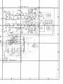
S WI T C H E S
;
SI SPEAKER
S
1
P O W E RO F F
2
S P A
3
SP OFF
52
FM MUTING
0N -'t
OFF
53
FUNCT|0N
At1
Ft1
PHONO
AUX
I
2
3
+
Sa
tTOR
TAPt MON
oN
-Q.EL-
Ss
MooE
++
STEREO
l'10N0
Ss
LOUDNESS
S4
A c V O L T A G ES E L E C T O R
220V 4_
240v
RESISTORS:
l N O H M, 1 / 4 W , t \ o / o T O L E R A N CU
EN
O T H E R W I SNEO T E DK = K . C, I M = M C }
:
CAPACITORS
lN,4F UNLESS0THERW
ISE NOTEDP=pF
AT
VOLTAGE
VI : STGNAL
I'
'-> mA : DC CURRENT
AT N0
V : DC VOLTAGE
AT NO
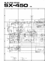
sx-450
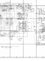
? 9. ADJUSTMENT
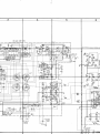
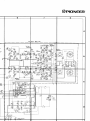
9.1 AM SECTION
1. Through a 1k ohm resistor, connect an AM
signal generator to the AM antenna terminal.
Set for 40OHz at 100dB and 3O% modulation.
2 Connect AC voltmeter to TAPE REC iack
(L or R).
Set FUNCTION switch to AM position.
4.
Set AM signal generator and SX-450 dial indication to point A (600kHz).
5 . Adjust T6 for maximum indication on AC
voltmeter.
c). Set AM signal generator and SX-450 dial indication to point C (1,400kH2).
7. Adjust TC4 for maximum indication on AC
voltmeter.
8. Again set AM signal generator and SX-450 dial
indication to point A.
9. Adjust bar antenna core for maximum indication on AC voltmeter.
10. Return AM signal generator and SX-450 dial
indication to point C.
11. Adjust TC5 for maximum indication on AC
voltmeter.
12. Repeat steps 4-11 to eliminate variations in
AC voltmeter indications at noint A and C.
F
AC voltmeter
A M s i g n a lg e n e r a t o r
q'
tr@
.{
)
q
1
25
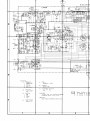
9.2 FM SECTION
1. Through 300 ohm dummy antenna, connect
FM signal generator to the 300 ohm FM
antenna terminals and set for 4OOHzat 100dB
and IO0% modulation.
2. Connect AC voltmeter and distortion meter to
TAPE REC jack (L or R).
3. Set FUNCTION switch to FM and MUTING
switch to OFF.
4. Set FM signal generator and SX-450 dial
indication to point A (90MHz).
5. Adjust T3 for maximum indication on AC
voltmeter.
6. Adjust T5 lower core for center of scale
indication on AM/FM meter.
7. Set FM signal generator for 9dB output and
adjust T1 and T2 for maximum indication on
AC voltmeter.
8. Set FM signal generator and SX-450 dial
indication to point C (106MHz).
A |/
9. Adjust TC3, then TC1 and TC2 for *u"i*rrindication on AC voltmeter.
10. Again set FM signal generatorand SX-450 dial
indication to point A.
11. Adjust T3, then T1 and T2 for maximum
indication on AC voltmeter.
12. Repeat steps 8-11 to eliminate variations in
sensitivity at points A and C.
13. Adjust "t4 for maximum sensitivity.
14. Detune to noise only and adjust T5 lower core
for center of scale indication on FM meter.
15. Set SX-450 dial indication to point B (98MHz)
and adjust FM signal generator for center of
scale indication on AM/FM meter.
16. Set FM signal generator output to 60dB and
adjust T5 upper core for minimum distortion.
17. Repeat steps 14-16 eliminate variation in mini- J" 'a
tl
mum distortion position.
ACvoltmeter
Distortion
FI
a)
0*FM signalgenerator
tr@
f'{
T2
T1
TC1
l\\ t
sx-450
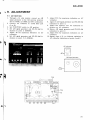
9.3 MPX SECTION
1. Through 300 ohm dummy antenna, connect
FM signal generator to 300 ohm FM antenna
terminals.
2. Connect multiplex signal generator to extemal
modulation terminals of FM signal generator.
3. Connect oscilloscopehorizontal input to MPX
signal pilot output and vertical input via probe
to TP (No. 13) of circuit board.
4. Set SX-450 dial indication to 98MHz and adjust
FM signal generator for center of scale indication on AM/FM meter.
5. With FM signal generator unmodulated, adjust
VR1 so that lissajous pattern on oscilloscope
becomes stationary as shown in Fig. 12.
6. With MPX signal generator modulation lkHz,
L + R 67.5kHz deviation and pilot 7.5kHz
deviation, adjust T4 for minimum distortion.
AC voltmeter
Distortion meter
F M s i g n a lg e n e r a t o r
Dummy load
tl'
Oscilloscope
M P X s i g n agl e n e r a t o r
'a
t
I
I
r|}
l
I
I
II
I
I
I
I
I
i
'
Fig.12
9 . 4 P O W E RA M P L I F I E R S E C T I O N( I D L E C U R R E N T }
1. Set BASS and TREBLE controls ro center
position.
2. Nothing should be connected to the INPUT
jacks of SX-450 and an 8 ohm dummy load
should be connected across the SPEAKER
terminal.
3. A DC voltmeter should be connect across
between terminal number 19 1+;, 20 (-) for
Left channel and 18 1+1, l7 (-) for Right
channel.
4. Cut the jumper lead, if the voltage less than
15mV.
DC Voltmeter
a r''
fi
j**'
ita
{
fNt #
ed
sx-450
) 1 0 . D r A L C O R DS T R T N G T N G
Removethe Front panel (Seepage 14, 15).
1. Turn tuning drum fully clockwise (as viewed
from X direction in Fig. 13).
2. Tie one end of cord to stud on inner section of
tuning drum (more easily performed by loosening setscrew and temporarily removing tuning
drum from shaft).
3. Passcord through pulley opening, make a half
tum around the pulley, then route in the
sequence:pulley A-Dial needle-pulley B-C.
4. Wind cord clockwise (as viewed from rear panel)
3 turns around dial shaft, then route to pulley D.
5. Wind 3 tums around dial pulley and tie to spring
so that the cord is under tention.
6.
Turn TUNING knob and confirm normal cord1
motion. then trim off excesscord.
7.
With tuning capacitorblades fully closed, move
t'
dial needle to starting point (left edge of scale).
8. Apply laquor to tied ends of cord.
D I A L N E E D L E I N S T A L L A T I O NC A U T I O N
Metal portion of dial pointer is plated.
If this section is touched directly by hand or
fingerprints and other impurities, it is difficult to
remove dirt from aventurine finish. As this is not
desirable in terms of both appearance and anticorrosion, take exteme care not to touch the
metal section when handling the dial needle.
I
Dial needle
Pulley D
Tuningdrum
Dial shaft
, . ' l
..'
\
-'
'rl
I
I
PulleyC
Spring hook
End: Tie to spring hook
Stud
Start: Fastenon end of the cord to start
Fis.13
29