1
Programmable Power Supplies
I
®
PM2811-PM2812-PM2813
PM2831-PM2832
Programmable Power Supplies
Users Manual
4822 872 00824
January 1997, Rev. 3, 5/98
© 1997 Fluke Corporation. All rights reserved. Printed in the Netherlands.
All product names are trademarks of their respective companies.
II
Users Manual
Programmable Power Supplies
III
LIMITED WARRANTY & LIMITATION OF LIABILITY
Each Fluke product is warranted to be free from defects in material and workmanship under
normal use and service. The warranty period is one year and begins on the date of
shipment. Parts, product repairs and services are warranted for 90 days. This warranty
extends only to the original buyer or end-user customer of a Fluke authorized reseller, and
does not apply to fuses, disposable batteries or to any product which, in Fluke's opinion, has
been misused, altered, neglected or damaged by accident or abnormal conditions of
operation or handling. Fluke warrants that software will operate substantially in accordance
with its functional specifications for 90 days and that it has been properly recorded on nondefective media. Fluke does not warrant that software will be error free or operate without
interruption.
Fluke authorized resellers shall extend this warranty on new and unused products to enduser customers only but have no authority to extend a greater or different warranty on behalf
of Fluke. Warranty support is available if product is purchased through a Fluke authorized
sales outlet or Buyer has paid the applicable international price. Fluke reserves the right to
invoice Buyer for importation costs of repair/replacement parts when product purchased in
one country is submitted for repair in another country.
Fluke's warranty obligation is limited, at Fluke's option, to refund of the purchase price, free
of charge repair, or replacement of a defective product which is returned to a Fluke
authorized service center within the warranty period.
To obtain warranty service, contact your nearest Fluke authorized service center or send the
product, with a description of the difficulty, postage and insurance prepaid (FOB
Destination), to the nearest Fluke authorized service center. Fluke assumes no risk for
damage in transit. Following warranty repair, the product will be returned to Buyer,
transportation prepaid (FOB Destination). If Fluke determines that the failure was caused
by misuse, alteration, accident or abnormal condition of operation or handling, Fluke will
provide an estimate of repair costs and obtain authorization before commencing the work.
Following repair, the product will be returned to the Buyer transportation prepaid and the
Buyer will be billed for the repair and return transportation charges (FOB Shipping Point).
THIS WARRANTY IS BUYER'S SOLE AND EXCLUSIVE REMEDY AND IS IN LIEU OF
ALL OTHER WARRANTIES, EXPRESS OR IMPLIED, INCLUDING BUT NOT LIMITED TO
ANY IMPLIED WARRANTY OF MERCHANTABILITY OR FITNESS FOR A PARTICULAR
PURPOSE. FLUKE SHALL NOT BE LIABLE FOR ANY SPECIAL, INDIRECT,
INCIDENTAL OR CONSEQUENTIAL DAMAGES OR LOSSES, INCLUDING LOSS OF
DATA, WHETHER ARISING FROM BREACH OF WARRANTY OR BASED ON
CONTRACT, TORT, RELIANCE OR ANY OTHER THEORY.
Since some countries or states do not allow limitation of the term of an implied warranty, or
exclusion or limitation of incidental or consequential damages, the limitations and
exclusions of this warranty may not apply to every buyer. If any provision of this Warranty is
held invalid or unenforceable by a court of competent jurisdiction, such holding will not affect
the validity or enforceability of any other provision.
Fluke Corporation, P.O. Box 9090, Everett, WA 98206-9090 USA, or
Fluke Industrial B.V., P.O. Box 680, 7600 AR, Almelo, The Netherlands
IV
Users Manual
SERVICE CENTERS
To locate an authorized service center, visit us on the World Wide Web:
http://www.fluke.com
or call Fluke using any of the phone numbers listed below:
+1-800-443-5853 in U.S.A. and Canada
+31-402-678-200 in Europe
+1-425-356-5500 from other countries
Programmable Power Supplies
CONTENS
1
2
I
Page
OPERATOR SAFETY . . . . . . . . . . . . . . . . . . . . . . . . . . . . . . . . . . . . 1-1
1.1
INTRODUCTION . . . . . . . . . . . . . . . . . . . . . . . . . . . . . . . . . . . . 1-1
1.2
SAFETY PRECAUTIONS. . . . . . . . . . . . . . . . . . . . . . . . . . . . . . 1-1
1.3
CAUTION AND WARNING STATEMENTS. . . . . . . . . . . . . . . . 1-1
1.4
SYMBOLS . . . . . . . . . . . . . . . . . . . . . . . . . . . . . . . . . . . . . . . . . 1-2
1.5
IMPAIRED SAFETY . . . . . . . . . . . . . . . . . . . . . . . . . . . . . . . . . . 1-2
INTRODUCTION . . . . . . . . . . . . . . . . . . . . . . . . . . . . . . . . . . . . . . . . . 2-1
2.1
INTRODUCTION TO YOUR PROGRAMMABLE
POWER SUPPLY . . . . . . . . . . . . . . . . . . . . . . . . . . . . . . . . . . . . 2-1
2.2
BASIC OPERATION . . . . . . . . . . . . . . . . . . . . . . . . . . . . . . . . . 2-4
2.2.1
Local operation . . . . . . . . . . . . . . . . . . . . . . . . . . . . . 2-6
2.2.2
Remote operation . . . . . . . . . . . . . . . . . . . . . . . . . . . 2-7
2.2.3
Sense modes . . . . . . . . . . . . . . . . . . . . . . . . . . . . . . 2-10
2.3
ADVANCED OPERATION . . . . . . . . . . . . . . . . . . . . . . . . . . . . 2-12
2.3.1
Output channel interconnections . . . . . . . . . . . . . . . 2-12
2.3.2
Multiple loads . . . . . . . . . . . . . . . . . . . . . . . . . . . . . . 2-13
II
Users Manual
3
INSTALLATION INSTRUCTIONS. . . . . . . . . . . . . . . . . . . . . . . . . . 3-1
4
3.1
INTRODUCTION . . . . . . . . . . . . . . . . . . . . . . . . . . . . . . . . . . . . 3-1
3.2
INITIAL INSPECTION . . . . . . . . . . . . . . . . . . . . . . . . . . . . . . . . 3-1
3.3
OPERATOR SAFETY INSTRUCTIONS . . . . . . . . . . . . . . . . . . 3-1
3.4
INSTALLATION . . . . . . . . . . . . . . . . . . . . . . . . . . . . . . . . . . . . .
3.4.1
Mechanical installation . . . . . . . . . . . . . . . . . . . . . . .
3.4.2
Electrical installation . . . . . . . . . . . . . . . . . . . . . . . . .
3.4.3
Front Connection Unit . . . . . . . . . . . . . . . . . . . . . . . .
3-2
3-2
3-3
3-4
3.5
OUTPUT CONNECTIONS . . . . . . . . . . . . . . . . . . . . . . . . . . . . .
3.5.1
Output channel connections . . . . . . . . . . . . . . . . . . .
3.5.2
GPIB connections . . . . . . . . . . . . . . . . . . . . . . . . . . .
3.5.3
Trigger bus connections . . . . . . . . . . . . . . . . . . . . . .
3-7
3-7
3-8
3-8
3.6
ACCEPTANCE TESTS . . . . . . . . . . . . . . . . . . . . . . . . . . . . . . . 3-9
3.6.1
Brief check. . . . . . . . . . . . . . . . . . . . . . . . . . . . . . . . . 3-9
3.6.2
Interface check . . . . . . . . . . . . . . . . . . . . . . . . . . . . 3-11
3.6.3
Performance Verification . . . . . . . . . . . . . . . . . . . . . 3-12
GETTING FAMILIAR WITH THE POWER SUPPLY . . . . . . . . . . 4-1
4.1
INITIAL SETUP OF YOUR POWER SUPPLY. . . . . . . . . . . . . . 4-1
4.1.1
Power up routine . . . . . . . . . . . . . . . . . . . . . . . . . . . . 4-1
4.1.2
Instrument identification. . . . . . . . . . . . . . . . . . . . . . . 4-2
4.2
FRONT PANEL LAYOUT . . . . . . . . . . . . . . . . . . . . . . . . . . . . . 4-3
4.2.1
Keyboard controls . . . . . . . . . . . . . . . . . . . . . . . . . . . 4-3
4.2.2
Display indicators . . . . . . . . . . . . . . . . . . . . . . . . . . . 4-6
4.3
OUTPUT CHANNEL CONNECTIONS. . . . . . . . . . . . . . . . . . . . 4-7
4.4
GETTING STARTED . . . . . . . . . . . . . . . . . . . . . . . . . . . . . . . . . 4-8
4.4.1
Selecting an output channel . . . . . . . . . . . . . . . . . . . 4-8
4.4.2
Setting an output voltage. . . . . . . . . . . . . . . . . . . . . . 4-9
4.4.3
Setting an output current . . . . . . . . . . . . . . . . . . . . . 4-10
Programmable Power Supplies
5
III
USING YOUR PROGRAMMABLE POWER SUPPLY . . . . . . . . 5-1
5.1
INTRODUCTION . . . . . . . . . . . . . . . . . . . . . . . . . . . . . . . . . . . . 5-1
5.2
LOCAL OPERATION . . . . . . . . . . . . . . . . . . . . . . . . . . . . . . . . . 5-2
5.3
REMOTE OPERATION . . . . . . . . . . . . . . . . . . . . . . . . . . . . . . . 5-3
5.4
OPERATING FEATURES . . . . . . . . . . . . . . . . . . . . . . . . . . . . . 5-4
5.5
HOW TO USE THE OPERATING FEATURES . . . . . . . . . . . . . 5-7
5.5.1
Output channel characteristics. . . . . . . . . . . . . . . . . . 5-7
5.5.2
Local and remote sensing . . . . . . . . . . . . . . . . . . . . 5-10
5.5.3
Constant voltage or constant current source . . . . . . 5-13
5.5.4
Store/recall function . . . . . . . . . . . . . . . . . . . . . . . . . 5-19
5.5.5
Step functions . . . . . . . . . . . . . . . . . . . . . . . . . . . . . 5-22
5.6
ADVANCED USE . . . . . . . . . . . . . . . . . . . . . . . . . . . . . . . . . . .
5.6.1
Parallel connection of output channels . . . . . . . . . .
5.6.2
Serial connection of output channels . . . . . . . . . . . .
5.6.3
Parallel connection of loads . . . . . . . . . . . . . . . . . . .
5.6.4
Tips for Remote Sensing Applications . . . . . . . . . . .
5-28
5-29
5-32
5-35
5-36
IV
Users Manual
APPENDIX A ACCESSORIES . . . . . . . . . . . . . . . . . . . . . . . . . . . . . . . A-1
A.1
Supplied with the instrument . . . . . . . . . . . . . . . . . . . . . . . . . . . A-1
A.2
Optional . . . . . . . . . . . . . . . . . . . . . . . . . . . . . . . . . . . . . . . . . . . A-1
APPENDIX B SCPI CONFORMANCE INFORMATION . . . . . . . . . . .B-1
B.1
IEEE 488.2-1987 . . . . . . . . . . . . . . . . . . . . . . . . . . . . . . . . . . . . B-1
B.2
SCPI Std 1993.0 Confirmed . . . . . . . . . . . . . . . . . . . . . . . . . . . B-1
B.3
SCPI approved . . . . . . . . . . . . . . . . . . . . . . . . . . . . . . . . . . . . . B-4
B.4
SCPI syntax and style . . . . . . . . . . . . . . . . . . . . . . . . . . . . . . . . B-5
APPENDIX C ABBREVIATIONS, SYMBOLS & TERMS . . . . . . . . . C-1
C.1
Abbreviations . . . . . . . . . . . . . . . . . . . . . . . . . . . . . . . . . . . . . . . C-1
C.2
Glossary of symbols . . . . . . . . . . . . . . . . . . . . . . . . . . . . . . . . . C-5
C.3
Glossary of terms . . . . . . . . . . . . . . . . . . . . . . . . . . . . . . . . . . . C-6
APPENDIX D APPLICATION FOR PM2812 AND PM2813 . . . . . . . D-1
INDEX . . . . . . . . . . . . . . . . . . . . . . . . . . . . . . . . . . . . . . . . . . . . . . . . . . . . . . I-1
Programmable Power Supplies
V
Thank you for purchasing this FLUKE power supply. It has been designed and
manufactured to the highest quality standards to give you many years of troublefree use.
The powerful operating features have been combined with an easy and logical
operation so that the full power of this instrument can be used every day. The
main operating features are:
•
•
•
•
•
•
•
•
•
•
•
•
•
•
Multiple output, dc power supply
Output modules with various voltage and current ratings
Suitable for GPIB as well as benchtop applications
Conforms to SCPI and IEEE 488.2 standards
Non volatile memory for 999 settings
Power down memory (front panel settings)
Readback of actual voltage and current
Manual and automatic step function
Overvoltage and overcurrent protection
Overtemperature and sense protection
Coupled protection of output channels
Closed case calibration facility (protected by password)
External trigger facilities (auto step)
Built-in self-test and diagnostics routines
VI
Users Manual
INITIAL INSPECTION
Check the contents of the shipment for completeness and note whether any
damage has occurred during transport. If the contents are incomplete, or if there
is damage to the instrument or its accessories, notify the FLUKE sales or service
office nearest you to facilitate the repair or replacement of the instrument or
accessories.
The following items must be included in the shipment:
•
Programmable Power Supply
•
Reference Manual English
•
Operation Manual English, or
Operation Manual German, or
Operation Manual French
•
Power Cord
•
Two spare fuses
•
Two mounting brackets (only for the 19 inch models)
For further information, refer to APPENDIX A, ‘Accessories’.
Programmable Power Supplies
VII
INSIDE THIS MANUAL
This operating manual has been aimed at the experienced user as well as the
user new to Programmable Power Supplies. It will help the reader to use and
operate the power supply manually (local operation) or from a PC via the GPIB
(remote operation).
1) OPERATOR SAFETY
Gives full information about safety aspects.
2) INTRODUCTION TO YOUR PROGRAMMABLE POWER SUPPLY
Describes what your power supply is and how you can use it.
3) INSTALLATION INSTRUCTIONS
Describes the steps necessary to prepare your power supply for use.
4) GETTING STARTED WITH YOUR PROGRAMMABLE POWER SUPPLY
Describes how to get started with some commonly used functions of the
power supply. A step-by-step tutorial describes how to operate the functions
in the local (manual) mode.
5) USING YOUR PROGRAMMABLE POWER SUPPLY
Gives functional information about how to use the power supply in the local as
well as the remote mode.
Additional information is available in the following appendices:
A) ACCESSORIES
Gives a functional overview of the accessories that are supplied or can be
ordered.
B) SCPI CONFORMANCE INFORMATION
Gives information about versions of the confirmed and approved SCPI
commands and queries.
C) ABBREVIATIONS, SYMBOLS & TERMS
D) APPLICATION FOR PM2812 AND PM2813
Gives support information to extend maximum current of the PM2812 or
PM2813 by parallel connection of channels
VIII
Users Manual
Operator Safety
1-1
1 OPERATOR SAFETY
Read this page carefully before beginning to install and use the instrument.
1.1 INTRODUCTION
The instrument described in this manual is designed to be used only by qualified
personnel.
WARNING:
Servicing described in this manual is to be done only by
qualified service personnel. To avoid electrical shock, do not
service the instrument unless you are qualified to do so.
1.2 SAFETY PRECAUTIONS
For the correct and safe use of this instrument it is essential that both operating
and service personnel follow generally accepted safety procedures in addition to
the safety precautions specified in this manual. Specific warning and caution
statements, where they apply, will be found throughout the manual. Where
necessary, the warning and caution statements and/or symbols are marked on
the instrument.
1.3 CAUTION AND WARNING STATEMENTS
CAUTION:
Is used to indicate correct operating or maintenance procedures in
order to prevent damage to or destruction of the equipment or other
property.
WARNING:
Calls attention to a potential danger that requires correct
procedures or practices to prevent personal injury.
1-2
Users Manual
1.4 SYMBOLS
Symbol
Meaning of symbol
See explanation in manual
Earth
Conformité Européenne
1.5 IMPAIRED SAFETY
Whenever it is likely that safety has been impaired, the instrument must be turned
off and disconnected from line power. The matter should then be referred to
qualified technicians. Safety is likely to be impaired if, for example, the instrument
does not output the expected power or shows visible damage.
Introduction to your PPS
2-1
2 INTRODUCTION
2.1 INTRODUCTION TO YOUR PROGRAMMABLE
POWER SUPPLY
The basic function of your programmable power supply (PPS) is to supply a
predefined dc voltage or current in a controlled way through an output channel.
Your power supply model can have one, two or three output channels. Unless
stated otherwise, the information in this manual applies to all models. For
technical and environmental performance specifications, refer to the Reference
Manual.
REMOTE OPERATION
The family of Programmable Power Supplies is primarily intended to be used
in an automatic system environment programmed via a controller. For that
reason the power supplies have been equipped with a GPIB interface and
conform to IEEE-488.2 as well as the SCPI 1993.0 standards. For remote
operation, refer to the Reference Manual (operating references).
LOCAL OPERATION
The power supplies can be used as bench-top instruments (stand-alone) via
their keypads and displays. For local operation, refer to section 4.4 (getting
started), section 5.4 (operating features) or the Reference Manual (operating
references).
Family overview
PM2811/xyz
PM2812/xyz
PM2813/xyz
PM2831/xyz
PM2832/xyz
Single Output System
Dual Output System
Triple Output System
Single Output System
Dual Output System
Country Version
1 = Euro
3 = USA
4 = UK
5 = Swiss
Revision Number
1 = Standard Version
5 = Version with Front Connection Option
(see section 3.4.3).
Number assigned to various output ratings.
2-2
Users Manual
FRONT PANEL
The front panel contains a keypad and LCD for dialogue with the operator.
Local operation (manual) of the power supply is done via the keypad. The
display is used for passing information to the operator, such as:
• response information for the operator, e.g., ADDRESS 12
• readback information, e.g., an output voltage and current
• status information, e.g., display of the REM text
• error messages, e.g., the OVERCURRENT message
Display
Single front panel (PM2811 only)
Display
Single, dual and triple output front panel
Introduction to your PPS
2-3
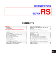
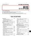
REAR PANEL
The rear panel contains connectors for the line power input, the output
channel(s), the trigger lines, and the GPIB (IEEE 488) interface. A fan
provides forced cooling of each output channel. The line power input module
also contains the line fuses, line filter, and the power switch.
For remote control, a GPIB (IEEE 488) connector for use with a GPIB
controller is provided.
Three SMB connectors for START, STEP, and READY are provided for
external triggering of the step mode and recalling stored instrument settings.
OUTPUT 1
30V 10A 60W
-S
-V
+V
0 1
+S
!
PHILIPS
PM2811/111
FUSES
110V 2.5AT/250V 9448 028 11011
220V 1.25AT/250V No.DM000599
MAX
240V
!
230V
50-60Hz
155VA
READY
START
STEP
IEEE488
ST5825
Single rear panel (PM2811 only)
OUTPUT 1
30V 10A 60W
-S
-V
+V
OUTPUT 3
30V 10A 60W
OUTPUT 2
30V 10A 60W
+S
-S
-V
+V
-S
+S
-V
+V
0 1
+S
!
PHILIPS
PM2813/011
FUSES
110V 6.3AM/250V 9448 028 13011
No.DM521001
220V 3AT/250V
MAX
240V
!
MAX
240V
!
MAX
240V
!
IEEE488
230V
50-60Hz
390VA
READY
START
STEP
ST5824
Output rear panel
2-4
Users Manual
2.2 BASIC OPERATION
The programmable power supplies offer a combination of programming
capabilities and a variety of dc output power ratings that make them ideal for
power systems applications. The +V and +S as well as the -V and -S terminals
have been connected to each other at the factory.
POWER
SUPPLY
+
output
channel
+S
+V
-V
-S
l
o
a
d
-
Each output channel can be programmed to the desired dc voltage or dc current
(output function). Self-contained measurement and readback capability eliminate
the need for using a separate multimeter to externally meter the output channel.
The readback voltage and current of the selected output channel can be
monitored on the front panel display (measure function). Protective circuitry within
the power supply limits or turns off an output channel when an abnormal condition
occurs. The following protection features have been implemented:
• OVERVOLTAGE and OVERCURRENT
• UNREGULATED OUTPUT
• OVERTEMPERATURE
• OUT OF SENSE CAPABILITY
• COUPLED PROTECTION (of output channels)
Each output channel can operate as a constant voltage source (CV mode), or
as a constant current source or current sink (PM283x only) (CC mode):
• As a constant voltage source the output voltage remains constant, while
the output current changes due to fluctuations of the load.
• As a constant current source the output current remains constant, while
the output voltage changes due to fluctuations of the load.
Introduction to your PPS
2-5
After power on, the programmable power supply performs a self-test. If the
selftest is succesful, the STANDBY, OPERATE, or CALIBRATION mode will be
entered. In the OPERATE mode, an output channel can be in the ENABLED or
DISABLED state (only multiple output models).
power on
SELF TEST
STANDBY
OPERATE
DISABLED
CALIBRATION
ENABLED
•
SELF-TEST
After power on the power supply will test itself. Depending on
the Power ON DEFinition (PONDEF), the STANDBY or
OPERATE mode is entered. The CALIBRATION mode can be
entered manually via the AUX key by pressing it during power
up, or remotely via the GPIB controller.
•
STANDBY
In this mode the power supply does not output power, i.e., all
output channels have been shut off. It is possible, however, to
verify or set voltage and current settings.
•
OPERATE
In this mode the power supply is able to output a voltage or a
current. For multiple output models each individual output
channel can be disabled (DISABLED state) or enabled
(ENABLED state). It is also possible to verify or set voltage
and current settings.
•
CALIBRATION In this mode the power supply can be calibrated. At the end
of the calibration, the power supply will enter STANDBY
mode.
The following diagram shows the possible output channel states:
OUTPUT CHANNEL
DISABLED
ENABLED
Power supply STANDBY
no power
no power
Power supply OPERATE
no power
power output
2-6
2.2.1
Users Manual
Local operation
Using the front panel keys, you can program an output channel voltage or current.
On the front panel display you can read back the actual voltage and current of the
selected output channel. Operating information about the instrument and the
selected output channel, as well as output-specific error messages, are shown on
the display in the following ways (see the following figure):
• text
• annunciators, pointing at abbreviations on the front panel right below the
display.
PM28xx programmable power supply xxV/yyA/zzW • • •
LCD display
text annunciators text
abbreviations
keypad
keypad
keypad
You can use the keypad as follows to control your power supply:
• control interface and general functions via a menu
• switch between the operate and standby mode
• set the supply to local control (if not remotely locked)
• reset the power supply, i.e., return to the ’power on’ state
• store/recall/step voltage and current settings (1 to 999) in the instrument’s
battery backed-up memory (recall memory)
You can use the keypad as follows to control one of the output channels:
• select an output channel (only for multiple output models)
• enable or disable an output channel (only for multiple output models)
• unmask, delay, or display the setting of bits in the fault register
• reset the overvoltage and overcurrent protection
You can use the keypad as follows to perform an output channel setting:
• set or change the output voltage or current
• set the overvoltage trip level
• enable or disable the overcurrent protection
Introduction to your PPS
2.2.2
2-7
Remote operation
Via the General Purpose Interface Bus (GPIB), you can program your
programmable power supply to receive input data and to send output data. An
example of input data (listener) is that a voltage and current can be programmed
directly to the selected output channel. An example of output data (talker) is the
readback voltage and current of the selected output channel.
IEEE 488.2 compatibility
IEEE 488.2 is a standard that is additional and complementary to the IEEE 488.1
standard. Your programmable power supply conforms to the IEEE 488.2
standard. For more information refer to the Reference Manual.
SCPI compatibility
SCPI (Standard Commands for Programmable Instruments) is a command
definition standard for programmable test and measurement instruments. Your
programmable power supply conforms to the SCPI standard. For more
information, refer to the Reference Manual.
2-8
Users Manual
The programmable functions have been implemented via the GPIB by means of
the following SCPI subsystems:
DISPlay
SYSTem
SOURce
voltage
output
channel 1
OUTPut
CALibration
INSTrument
ABORt
sense
input
channel 1
MEASure
step
INITiate
•
•
TEST
STATus
• •
• •
•
•
•
•
• •
• •
input/output
channel n
Introduction to your PPS
2-9
•
ABORt
This subsystem is used for stopping the step function of the power supply.
•
CALibration
This subsystem is used for calibration of the instrument. Your power supply
can be calibrated without removing the cover or removing the power supply
from your rack measurement setup. This feature allows you to calibrate the
power supply at its normal operating temperature. The recommended
calibration interval is one year. Refer to the Reference Manual for complete
calibration details.
•
DISPlay
This subsystem is used to control the front panel display.
•
INITiate
This subsytem is used to start up (initiate) the step function of the power
supply.
•
INSTrument
This subsystem is used to control the instrument functions.
•
MEASure
This subsystem is used to measure (readback) output voltage and output
current.
•
OUTPut
This subsystem is used to control an output channel.
•
SOURce
This subsystem is used for source and setting functions of an output channel,
such as : - source definitions
- voltage (protection) settings
- current (protection) settings
- automatic stepping
•
STATus
This subsystem is used for handling the device-dependent operational and
questionable status information.
•
SYSTem
This subsystem is used to handle system and control functions, such as:
- lockout front panel control
- define the ’power on clear’ behavior
- request for status information
•
TEST
This subsystem is used to test the instrument.
2 - 10
2.2.3
Users Manual
Sense modes
Each output channel has been provided with a set of four terminals. The inner
terminals have been marked as - V(oltage) and + V(oltage), while the outer
terminals have been marked as - S(ense) and + S(ense).
-S
-V
+V
+S
Each output channel can be connected to a load in two different ways:
• through the +V and -V terminals, causing the power supply to operate in
its local sense mode.
• through the +V and -V and +S and -S terminals, causing the power supply
to operate in its remote sense mode.
Local sensing
-S
-V
+V
+S
load
At delivery the sense terminals are interconnected with the voltage terminals. This
is called local sensing. If the voltage drop across both of the wires to the load is
negligible, the voltage at the load will equal the programmed value.
Introduction to your PPS
2 - 11
Remote sensing
-S
-V
+V
+S
load
If the voltage drop across the +V and -V wires to the load is substantial, the
voltage at the load will be less than the programmed value. To prevent the voltage
at the load from being less than the programmed value, the sense wires must also
be connected to the load (remote sensing). This way of sensing allows the power
supply to compensate for voltage drops in the wires between the power supply
and the load. The sense wires must be connected directly to the load poles.
Note:
Long sense wires are susceptible to noise pickup. To minimize noise
pickup, twist each pair of sense wires together. Shielding around the
sense wires may be necessary in more extreme cases.
2 - 12
Users Manual
2.3 ADVANCED OPERATION
2.3.1
Output channel interconnections
Identical output channels can be connected in the following ways to increase the
total output capability:
• In series to increase the output voltage capability. Refer to section 5.6.2
"Serial connection of output channels" for more information.
+
V1
L
O
A
D
–
+
Vload = V1 + V2
V2
–
•
Parallel to increase the output current capability. Refer to section 5.6.1
"Parallel connection of output channels" for more information.
I1
I2
+
+
V1
V2
–
–
CAUTION:
L
O
A
D
Iload = I1 + I2
Only output channels with equivalent voltage and current ratings
may be connected in series or parallel to prevent damage to one of
the channels. For maximum output capacity, refer to section 5.5.1
"Output channel ratings and characteristics". For more information
about connections, refer to section 5.6 "Advanced use".
Introduction to your PPS
2.3.2
2 - 13
Multiple loads
If more than one load is connected to an output channel, use separate wires to
connect each load. This minimizes mutual coupling effects and takes full
advantage of the power supply’s low output impedance. Each pair of wires should
be as short as possible to reduce wire inductance and noise pickup to prevent the
loads from mutually influencing each other, due to load fluctuations. The loads
must be connected in parallel, not in series.
-S
–
-V
+V
+
+S
–
load 1
+
load 2
CORRECT: Parallel connection of loads
-S
–
-V
+V
+S
+
load 1
–
+
load 2
+
–
WRONG: Series connection of loads
Note:
To prevent noise pickup, you are advised to twist the sense wires and
shield them from each other.
In principle there is no restriction about the number of loads that can be
connected. Remote voltage sensing is recommended if one load is more sensitive
than the other(s); therefore, sense directly at the most sensitive load.
Installation Instructions
3-1
3 INSTALLATION INSTRUCTIONS
3.1 INTRODUCTION
This section contains instructions for the following:
•
•
•
•
•
inspecting the contents of the shipment for completeness and/or damage
during transport (initial inspection)
ensuring the safety of the operator
installing the power supply
making the input and output connections
performing the installation acceptance checks
3.2 INITIAL INSPECTION
Inspect the contents of the shipment for completeness and note whether any
damage has occurred during transport. If the contents are not complete, or if there
is damage, inform your FLUKE Sales and Service Center so that repair or
replacement of the instrument can be arranged.
Pay special attention to the following parts :
• accessories to be supplied (refer to Appendix A).
• front panel keys and display.
• rear panel connectors and terminal blocks.
• cabinet surfaces.
The shipment must contain one power supply plus the accessories supplied. For
a complete list of accessories supplied, refer to the INITIAL INSPECTION page
in the front of this manual.
3.3 OPERATOR SAFETY INSTRUCTIONS
The instrument has been designed and tested in accordance with IEC Publication
1010 for Class 1 instruments and has been supplied in a safe condition. This
Operation Manual contains WARNING and CAUTION statements, that must be
followed by the user to ensure safe operation and to keep the instrument in a safe
condition.
3-2
Users Manual
The instrument described in this manual is to be used by properly trained
personnel.
Do not remove the cover or perform any adjustment, maintenance, or repair
unless you are qualified to do so and are aware of the hazards involved.
Symbol
Before connecting the instrument to line power, ensure that the
power ground is functioning correctly. Before any other connection
is made, the instrument must be connected to the earth (ground)
conductor via the three-conductor power cord. The power plug
must be inserted into a socket outlet provided with ground contact.
The grounding protection must not be defeated by use of an
extension cord without a ground conductor.
WARNING : Any interruption of the protective conductor inside or outside
the instrument or disconnection of the protective ground
terminal is likely to make the instrument dangerous.
Intentional interruption is prohibited.
The instrument is shipped from the factory with a power cord that has a plug
appropriate for the country in which it is sold. If a different power plug or power
cord is required, contact your Fluke Sales and Service Center.
CAUTION: When an instrument is brought from a cold into a warm environment,
condensation may cause a hazardous condition; therefore, make
sure that the grounding requirements are strictly adhered to.
3.4 INSTALLATION
3.4.1
Mechanical installation
The instrument is fan cooled and must be installed in a location that allows
sufficient space at the three important sides: rear, left, and right. Each side must
have a space of at least 1 inch (25 mm). The fan, located at the rear, cools the
instrument by drawing air into the openings at the rear and exhausting it through
openings on the sides. Each instrument output channel has its own fan.
Installation Instructions
3.4.2
3-3
Electrical installation
Pre-installation checks:
•
Read Chapter 1 "OPERATOR SAFETY" before making any connections.
•
Before inserting the power plug into the power supply, ensure that the
ground conductor is functioning correctly.
Check that this instrument is suitable for the local situation as indicated on the
model number plate (sticker) on the rear panel.
NOTE : If the instrument must be wired to conform to local power, contact your
FLUKE Sales and Service Center to have it modified.
The power inlet module, located at the rear, is an integral power adapter and
includes the power input socket, the holder for the two power fuses and the
POWER ON/OFF (1/0) switch. The two power fuses are located behind the flap
next to the power input socket.
WARNING:
When a fuse must be replaced, the instrument must be turned
off and disconnected from the power. Refer to Chapter 2 in the
Reference Manual.
3-4
3.4.3
Users Manual
Front Connection Unit
Introduction
This section describes the use and capabilities of the Front Connection Unit,
mounted underneath the power supply.
The Front Connection Unit provides the interconnections between the rear and
front terminals.
The following programmable power supply types have a front connection unit:
• single output model: PM2811/x5z
• dual output model : PM2812/x5z
• triple output model : PM2813/x5z
• single output model: PM2831/x5z
• dual output model : PM2832/x5z
x = Number assigned to various output ratings
z = Country version
Basic operation
Every output channel has been provided with four output terminals, a ground
terminal, and a SENSE switch.
FOUR OUTPUT TERMINALS
The inner 2 banana sockets are for the power output, i.e., +V and -V. The outer
2 banana sockets are for the sense input, i.e., +S and -S.
ONE GROUND TERMINAL
The ground (earth)terminal has been connected to the housing for grounding
and shielding purposes.
ONE SENSE SWITCH
This switch enables you to select local or remote sensing.
Note:
Switching from remote to local or from local to remote may cause a
sense break detection. To avoid this, it is advised to switch modes only
at power off.
Electrical properties
The maximum voltage between any terminal and ground
The maximum current through an output terminal
The maximum current that may be switched
: 240 V
: 15 A
:
4A
Installation Instructions
3-5
Local sensing
The SENSE switch is in ’LOCAL’ position if S1 is ’closed’.
+S
S1
+V
Load
S1
-V
-S
CAUTION: Do not connect a load to the sense terminals +S and -S, because the
maximum current through the switch is limited to 4 A. Currents
exceeding this limit will damage the switch.
Also make sure that the sense wires (used for remote sensing) are
disconnected from the sense terminals to prevent current through the
sense switches.
Remote sensing
The SENSE switch is in ’REMOTE’ position if S1 is ’open’. The sense terminals
must be connected to the load.
+S
S1
+V
Load
S1
-V
-S
3-6
Half size model
Full size model
Users Manual
Installation Instructions
3-7
3.5 OUTPUT CONNECTIONS
This section describes the following output connections:
• output channel terminals
• GPIB connector
• trigger bus SMB connectors
3.5.1
Output channel connections
The number of the output channels of the various power supplies is indicated in
the last figure of the model number (single, dual or triple).
= PM2811 and PM2831 (single)
= PM2812 and PM2832 (dual)
= PM2813 (triple)
OUTPUT
CHANNEL 1
OUTPUT
CHANNEL 2
OUTPUT
CHANNEL 3
Every output channel connector is identical and consists of four terminals, i.e., two
Voltage output terminals and two sense input terminals. A load can be connected
in one of the following ways:
• to the + and - voltage terminals (local sensing)
• to the + and - voltage and sense terminals (remote sensing)
(local sensing)
-S
-V
+V
load
WARNING:
(remote sensing)
+S
-S
-V
+V
+S
load
To prevent SHOCK HAZARD, turn off the power before making
rear output channel connections. All wires and straps must be
properly insulated, and connected with terminal block screws
securely tightened. Before any connection can be made, the
plastic terminal block cover must be unscrewed and removed.
When the connections have been made, the plastic terminal
block cover must be reinstalled again.
3-8
3.5.2
Users Manual
GPIB connections
The GPIB (General Purpose Interface Bus) is identical to the IEC 625 or IEEE 488
interface bus. At the rear you will find a 24-pin female connector in which the
connector pinning assignment is in accordance with IEEE 488.2 - 1987. An IEEE
cable connects your power supply via an IEEE interface board to a controller.
SHIELD SRQ NDAC DAV DIO4 DIO2
NR
ATN IFC FD EO1 DIO3 DIO1
12
1
24
13
GND GND GND REN DIO7 DIO5
11
9
7
LOGIC GND GND GND DIO8 DIO6
GND 10
8
6
ST6064
Figure 3.4 IEEE 488/IEC 625 Connections
3.5.3
Trigger bus connections
There are three SMB connectors at the rear: START, STEP, and READY.
The modes and functions of the connectors are shown in the following table.
NAME
MODE
FUNCTION
START
input
Enables stepping via the STEP input.
STEP
input
Executes the next step.
READY
output
Indicates whether a step is finished (ready for the next step).
The trigger bus connectors can be used to recall output channel settings from the
recall memory. For more information, refer to section 5.5.5 "Step functions".
Installation Instructions
3-9
3.6 ACCEPTANCE TESTS
The acceptance tests give information about the correct operation of the
instrument after installation.
The interface test must be performed when using the programmable power
supply for remote operation via the Controller/GPIB interface.
3.6.1
Brief check
After turning on your power supply, the following self tests on the hardware parts
will be performed automatically:
• ROM test
• RAM test
• GPIB controller test
• Microprocessor timer test
• Communication (D2B) test
• Display controller test
• ADDA output channel(s) test
The tests will not show up on the display unless an error is detected. In the case
of a hardware error, the following text + error code is displayed:
n
= Indication of the error source.
ddd = Summation of the decimal values of the
individual errors.
ERROR n:ddd
The following error codes are possible:
n = 0: Main CPU error
DECIMAL
128
64
32
16
8
4
2
1
ERROR DESCRIPTION
Display controller failure.
Bank switch failure.
Not used.
D2B failure.
IEEE controller failure.
Processor timer failure.
RAM failure.
ROM failure.
3 - 10
Users Manual
n = 1, 2, or 3: CPU error of output channel 1, 2, or 3
DECIMAL
128
64
32
16
8
4
2
1
ERROR DESCRIPTION
Not used.
ROM checksum error.
Configuration checksum error.
Calibration checksum error.
Checksum error of the default settings.
Processor timer failure.
Not used.
Output channel not responding.
If the display is correct, character # will be displayed on the 16 character
positions. Also the text (ENABLED 1 2 3 4 5 6 7 t t t t t t
REM SRQ) will
be displayed for 1 second.
#
#
#
#
#
#
ENABLED 1 2 3 4 5 6 7
#
#
#
#
#
#
t
t
t
t
t
t
#
#
#
REM
#
SRQ
Next, the text I N I T I A L I Z I N G will be displayed for 1 second. If the mode after
power on is OPERATE, the readback voltage and current will be displayed if the
output is not DISABLED.
If not in OPERATE mode, the display shows STANDBY.
If a failure occurs during one of the tests, inform your FLUKE Sales and Service
Center so that repair or replacement of the instrument can be arranged.
These tests take a few seconds to run. The instrument will be ready for use when
the message STANDBY or the readback voltage and current appears on the
display.
Installation Instructions
3.6.2
3 - 11
Interface check
To perform the GPIB interface check, the power supply must be connected to the
controller via the GPIB; therefore, you need a GPIB interface card + software
GPIB drivers + a programming language.
The various parts of the following interface check must be executed sequentially.
Your power supply goes into the remote state when the first command is sent via
the GPIB. However, the results of programmed commands can still be monitored
on the display, e.g., the readback voltage and current. Also the text REM will be
displayed in the remote state.
The interface check consists of the following parts:
Check the GPIB address setting under the AUX menu.
Identification query
send → *IDN?
read ← PHILIPS,PM28nn/xy,0,Va.b
Notes: • nn = 11, 12, 13, 31 or 32
• x is the model indication
• y is the hardware version
• a.b = the firmware version
send → *TST?
Read result of power on test.
read ← <response_string>
IF <response_string> = 0 THEN test result is correct
ELSE display controller failure
Selftest power supply query.
send → :TEST:SYSTEM?
read ← <response_string>
IF <response_string> = 0 THEN test result is correct
ELSE the <response_string> = hardware error number
send → :INST:NSEL 1
Select output channel 1 (only for
multiple output models).
Selftest of the output channel 1.
send → :TEST:INSTRUMENT?
read ← <response_string>
IF <response_string> = 0 THEN test result is correct
ELSE the <response_string> = hardware error number
Repeat this check for all available output channels.
Note:
For meaning of the hardware error numbers, refer to section 3.6.1 "Brief
check" or to "Error Messages" in the Reference Manual.
3 - 12
Users Manual
The following check can be executed for all available output channels. A choice
has been made for output channel 1 of a multiple output model. For single output
models, the output channel does not have to be selected and the channel
indication will not be displayed.
Use the SELECT key to select the output channel to be displayed (only for
multiple output models).
send → :INST:NSEL 1
Select output channel 1.
send → :OUTP:STAT ON
Enable selected output channel.
Read on the display: 1
STANDBY
ENABLED 1
send → :INST:STAT ON
Read on the display: 1
Set power supply in OPERATE mode.
xx.xxV
ENABLED 1
Note:
REM
yy.yyA
REM
The channel indication (n) and the text "ENABLED n" will be displayed
only on multiple output models.
If a failure occurs during one of the GPIB interface tests, inform your FLUKE Sales
and Service Center so that repair or replacement of the instrument can be
arranged.
3.6.3
Performance Verification
If the brief check (section 3.6.1) and the interface check (section 3.6.2) pass
successfully without error messages, you may carry out a performance check
before starting to use the power supply.
Appendix B in the Reference Manual gives a complete and simple procedure to
verify the performance of your power supply.
Getting Familair with the Power Supply
4-1
4 GETTING FAMILIAR WITH THE POWER
SUPPLY
This chapter will help the user new to programmable power supplies.
4.1 INITIAL SETUP OF YOUR POWER SUPPLY
4.1.1
Power up routine
WARNING:
0
Before you turn on your power supply, make sure that the
power input voltage matches the power voltage specifications
on the decal on the rear of your power supply. Refer to section
3.4.2 "Installation" for instructions on how to check this.
Turn the power on by pressing the switch at the rear. The power
supply performs a series of self tests that last about 5 seconds.
Normal self test indications
After the power supply has executed the self tests, all characters and
annunciators will be displayed, followed by the message INITIALIZING. At the
end of the self tests, the supply is in the standby mode (STANDBY displayed) or
in the operate mode (actual voltage and current displayed).
Self test errors
If a power-on self test fails, all output channels will remain disabled, and the
display will indicate the type of failure and the output channel on which it occurred.
If this is the case, refer to section 3.6 "Acceptance tests".
4-2
4.1.2
Users Manual
Instrument identification
Your power supply can be identified by its model number and version number. At
delivery the power supply has a default IEEE device address. To identify your
power supply, proceed as follows:
1) Start up the identification by pressing:
the AUX key as many times as necessary to dislay the following:
ADDRESS
Note:
aa
The address aa is the actual GPIB device address (default = 28).
2) Proceed with the identification by pressing:
the AUX key again so that the display shows the following:
PM28nn
Note :
Vx.x
y:zz
- PM28nn is the model number of the power supply.
- Vx.x is the firmware version of the power supply.
- y is the number of the output channel (1, 2 or 3).
- zz is the firmware version of the output channel.
The firmware versions of all output channels can be verified by pressing
SELECT to change Y (output channel number) on the display.
Note:
The SELECT function is applicable only for multiple output models.
3) Finish the identification by pressing:
ENTER .
Getting Familair with the Power Supply
4-3
4.2 FRONT PANEL LAYOUT
The following sections describe how to use the front panel control keys in
combination with the 16-character display and the annunciators concerned. To be
able to use the front panel keys, the power supply must be in the local mode. If
the supply is in the remote mode (REM text displayed), press LCL .
If the power supply does not react after you press the LCL key, this key is disabled
remotely by the Local Lockout (LLO) command from the GPIB controller.
Pressing the front panel keys when the power supply is in the remote mode, will
have no effect on programmed settings. It is, however, possible to view the actual
settings on the front panel display, by using the front panel keys SELECT, V, I,
OVP, DELAY, UNMASK, DISP, and AUX.
4.2.1
Keyboard controls
The front panel keyboard controls the following power supply functions:
1
2
3
4
5
6
8
7
LCL
AUX
OUTPUT
OPR
STBY
RESET
25
SET
SELECT
ENABLE
DISABLE
24
FUNCTION
OUTPUT control
SET output
FAULT
V
I
OVP
DELAY
RESET
OCP EN
OCP DIS
UNMASK
DISP
22
21
20
23
KEY
− V +
−
I
+
9
10
7
8
9
STORE
11
4
5
6
RECALL
12
1
2
3
STEP
13
OFF
.
ENTER
14
ON
0
19 18 17
16
15
ST6628
DESCRIPTION
1
OPR
STBY
2
SELECT
Select an individual channel (applicable only
for multiple output models).
24
ENABLE
DISABLE
Enable/disable the selected channel
(applicable only for multiple output models).
3
V
Verify/set the output voltage of the selected
channel.
Toggle between OPERATE and STANDBY.
4-4
FAULT handling
Adjust output
Numeric input
Users Manual
23
I
4
OVP
22
OCP EN
OCP DIS
Enable/disable the overcurrent protection of
the selected channel.
5
DELAY
Verify/set the reprogramming delay
21
UNMASK
Verify/set the bit mask of the fault register.
20
DISP
Show the contents of the fault register.
6
RESET
Reset the overvoltage/overcurrent/fail
protection.
7
− V +
19
−
I
10
0
...
17
0
OFF
Turn off key.
18
1
ON
Turn on key.
16
.
Verify/set the output current of the selected
channel.
Instrument control
9
Adjust the output voltage of the selected
channel. *)
+
Adjust the output current of the selected
channel. *)
*) Only in OPERATE mode.
9
Input a decimal number.
Input a decimal point.
Erase previous key stroke (backspace) or
leave the STEP function.
15
14
Verify/set the overvoltage trip level of the
selected channel.
ENTER
AUX
1)
Enter the input value or exit the current
function.
Step through the following control functions:
a) Enter the STEP MENU function (press
ENTER).
- Set AUTO STEP function on or off.
- Program the step TIME INTerval.
- Set CONTINUOUS step function on or off.
- Define START AT entry of loop sequence.
- Define STOP AT entry of loop sequence.
b) COUPLE voltage and current
PARAmeters.
Getting Familair with the Power Supply
4-5
c) COUPLE PROTection of all output
channels.
d) Set STandBY AT Power ON behavior on or
off.
e) Adjust the CONTRAST of the display (0-9).
f) LOCK the KEYboard 2).
g) Verify/set the GPIB ADDRESS (0 - 30).
h) Verify the identity and firmware version of
the power supply + its output channel(s).
i) Verify/set the CALlibration access CODE
LCL
Switch the power supply to local control.
11
STORE
Store the voltage and current settings of all
output channels (999 store addresses).
12
RECALL
Recall the stored voltage and current settings
from all output channels (999 recall
addresses).
13
STEP
Step from one recalled group of settings to the
next group of settings.
8
25
RESET
Pencil point operation push button to reset the
power supply while power is on.
1) The CALIBRATION mode is entered when you turn on the power supply while
pressing the AUX key.
2) To unlock the keyboard, press the ENTER key for approximately 5 seconds.
4-6
4.2.2
Users Manual
Display indicators
In the OPERATE mode, the display can show up to 16 characters, which are
refreshed four times per second.
On the front plate just below the display, a number of status abbreviations, e.g.,
CV (Constant Voltage), have been placed. Above each status abbreviation an
annunciator (W sign) can be displayed to indicate the validity of the corresponding
status abbreviation.
The enabled output channels (1 to 3) in the OPERATE mode plus the REM and
SRQ status abbreviations can also be displayed.
Example of a voltage setting (Vset) for output channel 1:
selected output channel
selected function
1
V
S
E
set value
T
1
W
ENABLED 1 2 3
STEP
Note:
.
2
W
3
4
REM
V
SRQ
FLT CV CC OCP
EN
The output channel indication is displayed only for multiple output
channel models.
Example of readback data for output channel 2:
selected output channel
readback current
readback voltage
2
5
.
0
STEP
Note:
3
V
0
W
ENABLED 1 2 3
.
W
2
6
3
REM
A
SRQ
FLT CV CC OCP
EN
The output channel indication is displayed only for multiple output
channel models.
Getting Familair with the Power Supply
4-7
4.3 OUTPUT CHANNEL CONNECTIONS
WARNING:
To prevent SHOCK HAZARD, turn off the line power before
making output channel connections or disable the output
channel concerned. All wires and straps must be properly
insulated, and connected with terminal block screws securely
tightened. Before any connection can be made, the plastic
terminal block cover must be unscrewed and removed. When
the connections have been made, the plastic terminal block
cover must be secured again.
Each output channel has been provided with a set of four terminals. The inner two
have been marked as - V(oltage) and + V(oltage), while the outer two have been
marked as - S(ense) and + S(ense). At delivery the +V and +S, as well as the -V
and -S terminals have been interconnected by straps.
Rear view of an output channel connected to a load:
(local sensing)
(remote sensing)
-S
-V
+V
load
+S
-S
-V
+V
+S
load
The voltage at the sense terminal(s) equals the programmed value. The voltage
at a connected load may differ from the programmed value, because of a voltage
drop depending on the resistance of the wires to the load and the current through
the load.
If the voltage drop is negligible, the load wires only have to be connected to the
+V and -V terminals. This is called ’local sensing’.
However, if the voltage drop is significant, the voltage at the load can differ from
the programmed value. To prevent this, the straps between the +V and +S and V and -S terminals must be removed and the load wires must also be connected
to the +S and -S terminals. This is called ’remote sensing’.
Note:
The terminals have been shielded with a plastic block cover which must
be removed before any connection can be made.
WARNING:
To avoid FIRE HAZARD, select a wire large enough to carry
short-circuit current without overheating. Two factors must be
considered when selecting the wire size for load connections:
- Conductor temperature, i.e., the current-carrying capacity.
- Total voltage drop, i.e., the wire length and thickness.
4-8
Users Manual
4.4 GETTING STARTED
The various parts of this tutorial must be executed sequentially. Before starting
with this tutorial, make sure the power supply is in the local state. If the supply is
in the remote state (REM is displayed), press LCL . If the REM text does not
disappear, the LCL key is disabled remotely by the Local Lockout (LLO) command
from the GPIB controller.
If the display shows the measured output voltage and current of one of the output
channels, the power supply is in the OPERATE mode. Before starting with the
tutorial, set the power supply to the STANDBY mode by pressing
the OPR/STBY key.
Notes:
•
•
4.4.1
For multiple output models the selected output channel number n will
be displayed.
For a single output model the number n will not be displayed.
Selecting an output channel
Make an output channel active as follows.
If you have a single output model, skip the first three lines of the following
sequence.
Press SELECT to select the desired output channel.
The display then shows the selected output channel.
Press
ENABLE
DISABLE
to enable the selected output (if not already enabled).
The display shows: n
STANDBY
ENABLED n
Press
OPR
STBY
to set the power supply to OPERATE mode.
The display shows: n
xx.xxV
ENABLED n
yy.yyA
Getting Familair with the Power Supply
4.4.2
4-9
Setting an output voltage
Do not connect any load. The +V and +S terminals must be interconnected as well
as the -V and -S terminals.
1) Set the voltage of the selected output channel to 5V by pressing:
V
5
The display shows: n
VSET
5
V
2) Enter the output voltage setting by pressing ENTER
Check that the display reads approximately 5V. Also check that the CV
annunciator is on, indicating that the selected output channel is in the
Constant Voltage mode.
3) Program the overvoltage trip level to 7V by pressing:
OVP
7
The display shows: n
OVSET
7
V
4) Enter the overvoltage trip level setting by pressing ENTER
5) Set the voltage of the selected output channel to 8V by pressing:
V
8
The display shows: n
8
VSET
V
6) Enter the output voltage setting by pressing ENTER , and
check that the display reads: n
OVERVOLTAGE
7) Set the output voltage to 6V and reset the overvoltage protection by pressing:
V
6
ENTER
RESET
Check that the display reads approximately 6V.
4 - 10
4.4.3
Users Manual
Setting an output current
1) Turn off the power supply.
2) Remove the plastic terminal block cover from the output to be tested.
Connect a short circuit (jumper wire) between the - V(oltage) and + V(oltage)
output terminals as follows:
-S
-V
Note:
+V
+S
The diameter of the jumper wire must be large enough to carry the
maximum short-circuit current.
3) Turn on the power supply. If the supply is in the STANDBY mode or if the
selected output channel is disabled, repeat the tutorial commands given in
section 4.4.1.
4) Check that the CC annunciator is on, indicating that the output channel is in
the Constant Current mode.
5) Set the current of the selected output channel to 0.5A by pressing:
I
.
5
The display shows: n
ISET
0.5
A
6) Enter the output current setting by pressing ENTER , and
check that the display reads approximately 0.5A.
7) Enable the overcurrent protection circuit (OCP) by pressing:
OCP EN
OCP DIS
8) The display shows: n O V E R C U R R E N T
The OCP EN annunciator is on, indicating that overcurrent protection is
enabled. The CC annunciator should be off.
Getting Familair with the Power Supply
9)
4 - 11
Disable the overcurrent protection and reset the output channel by pressing:
OCP EN
OCP DIS
RESET
Check that the display reads approximately 0.5A.
Also check that the CC annunciator is on, indicating that the output channel
is in the ’Constant Current’ mode again.
10) Turn off the power supply.
11) Remove the jumper wire between the - V(oltage) and + V(oltage) output
terminals and reattach the terminal block cover.
4 - 12
Users Manual
Using your Programmable Power Supply
5-1
5 USING YOUR PROGRAMMABLE
POWER SUPPLY
5.1 INTRODUCTION
This chapter contains functional information about using your programmable power
supply (PPS). It covers basic information, such as connecting a load to an output
channel, and more advanced information such as the following:
1) Connecting loads in parallel to an output channel.
2) Connecting output channels in series to a load to increase the maximum
output voltage or connecting them in parallel to a load to increase the output
current.
This chapter also contains information about main operating features and
describes how to use those features. You can use your programmable power
supply in one of the following ways:
1) In a system environment, via a system controller (PC + IEEE interface). This
is called "remote operation".
2) As a bench-top instrument, using the front panel keys, indicators and display.
This is called "local operation".
Each output channel of the power supply is a dc power source with controlled
limits for power, voltage, and current. An output channel can operate as a
constant voltage (CV) source, as a constant current (CC) source, or as a constant
current (CC) sink (PM283x only) depending on voltage/current settings and load
conditions. The maximum output voltage or current is limited by the following:
1) The maximum voltage and current cannot exceed the output channel-specific
limits.
2) The product of voltage and current cannot exceed the output channel-specific
power limit according to the formula Vset x Iset ≤ Pmax.
For output limits, refer to section 5.5.1 "Output channel ratings and
characteristics".
CAUTION: You may turn on your power supply if you are sure that the
installation instructions as described in Chapter 3 have been
followed. The power supply is ready for use within a few seconds
after power-up. After a warm-up time of 30 minutes, your power
supply meets the specifications listed in the Reference Manual.
5-2
Users Manual
5.2 LOCAL OPERATION
Local operation of your power supply is done through the front panel keys and
display. Operational and error information is shown on the display. The keys are
used for operator communication and have been placed into functional groups.
This makes the functional use of the power supply very easy:
•
•
•
•
•
•
OUTPUT control
SET output
FAULT handling
output adjustment
numeric control
instrument control
OUTPUT control
SET output
FAULT handling
output adjustment
: control over the output channels
: setting a channel output
: fault handling per output channel
: adjusting a channel output
: input of figures or special keys
: control over the instrument
reset
OPR/STBY
SELECT
ENABLE/DISABLE
reset the power supply
set OPERATE or STANDBY mode
select output channel *
enable/disable output channel *
V
I
OVP
OCP EN/OCP DIS
set output voltage
set output current
set overvoltage protection trip level
enable/disable overcurrent
protection
DELAY
RESET
UNMASK
DISP
verify/set reprogramming delay
reset protection circuits
verify/set fault mask
display fault register
-V+
-I+
adjust output voltage
adjust output current
figures
0 (OFF)
1 (ON)
2 ... 9
numeric control
W
specials
instrument control
Note:
LCL
AUX
STORE
RECALL
STEP
(backspace)
ENTER
• (dot)
gain local control
perform system functions
store voltage/current settings
recall voltage/current settings
step through voltage/current settings
* = applies to multiple output models only.
Using your Programmable Power Supply
5-3
5.3 REMOTE OPERATION
In the remote mode, pressing the front panel keys will have no effect on
programmed settings. It is, however, possible to view the actual settings on the
front panel display, by pressing the front panel keys SELECT, V, I, OVP, DELAY,
UNMASK, DISP, LCL, and AUX.
SCPI (Standard Commands for Programmable Instruments) is a standardized set
of commands to be used for remote control of programmable test and measure
instruments. It defines the syntax and semantics that the controller must use to
communicate with an instrument, and is implemented in the instrument’s
firmware.
Please, read the users handbook ‘Standard Commands for Programmable
Instruments? to get familiar with the SCPI and IEEE-488.2 standards. This
handbook can be ordered at your local Fluke representative. See Appendix A for
more information.
5-4
Users Manual
5.4 OPERATING FEATURES
Your programmable power supply is equipped with a GPIB interface, which
conforms to the IEEE-488.2 standard and the SCPI protocol (Standard
Commands for Programmable Instruments). The power supply can be
programmed to operate in a remotely controlled instrumentation system via the
GPIB.
You can use each output channel of the power supply as a constant voltage
source (CV mode), as a constant current source (CC mode), or as a constant
current sink (PM283x only). There are three instrument types available:
• single output channel power supply
• dual output channel power supply
• triple output channel power supply
A channel can have various output voltage and output current ratings.
The operating structure and operating principles are identical for each instrument
type and for each output channel.
The following features have been implemented in each power supply:
•
Power on self-test and diagnostics routines.
•
Readback capability of the measured voltage and current of each output
channel.
•
Each output channel offers the ability to sense locally or remotely. For remote
sensing, the sense terminals (+S and -S) must be connected to the load
instead of the +V and -V output terminals; then the programmed voltage (Vset)
is guaranteed to be across the load, in spite of the voltage drop in the wires to
the load.
•
A nonvolatile memory (battery backed up). This enables you to:
- store and recall voltage and current settings of all output channels
(refer to section 5.5.4 "Store/Recall function")
- save and recall the front panel settings (refer to the common
commands *SAV and *RCL).
In this way, stored settings can be recalled, even after a long period of power
off.
Using your Programmable Power Supply
•
5-5
Extended STEP possibilities, i.e., the capability to step sequentially through a
number of predefined voltage and current settings. This can
be done: - Manually using the STEP key.
- Automatically at predefined intervals (internal timer)
- Externally - by a STEP line trigger via the trigger bus
- by a trigger via the GPIB interface
You can use this feature to generate test patterns and simulate ramp
functions. The following table shows in which operating modes the STEP
capabilities can be used:
TRIGGER SOURCE
LOCAL OPERATION
REMOTE OPERATION
MANUAL
AUTOMATIC
STEP key
AUX key
EXTERNAL-STEP line
EXTERNAL-GPIB
STEP line
not applicable
Not possible
:SOURCE:LIST:... commands
:INIT / :ABORT command
Trigger STEP line trigger
*TRG / GET command
•
Closed-case calibration, i.e., your power supply can be calibrated without
removing the cover or even without removing the instrument from your system
cabinet. This feature allows you to calibrate your power supply at its normal
operating temperature. The recommended calibration interval is one year.
Refer to section 7.3.3 "Calibration" for complete calibration details.
•
Protection circuitry for safe operation of your power supply:
- by providing protection against OVERTEMPERATURE
- by reporting an UNREGULATED output channel situation
- by reporting conflicts in parameter settings
- by reporting erroneous situations during operation
•
Protection circuitry to protect a connected load:
- against OVERVOLTAGE on each output channel
- against OVERCURRENT on each output channel
- against exceeding the sense capability on each output channel
- with the ability to couple the voltage and current setting of the same output
channel (not valid for the linear power supplies)
- with the ability to couple the protection mechanisms of different output
channels of the same power supply
To increase the total output power, connect an output channel to another output
channel of the same voltage and current ratings. The connection can be made in
series or in parallel. The output channels to be connected can be from the same
power supply or from different power supplies; however, the capability of coupling
protection mechanisms is only possible for output channels within the same
power supply.
5-6
Users Manual
The following illustrations show the possible connections.
•
SERIES connection to increase the total output voltage capability:
+
+
V1
L
O
A
D
–
+
V2
Vload =V1 + V2
Iload = Vload / Rload
Pload = Vload x Iload
-
–
•
WARNING:
To guarantee the safe use of the power supply, the total
maximum voltage at each terminal must not exceed 240V
with respect to ground.
Examples:
• 2x 60V/2A = 120V/2A
• 2x 120V/1A= 240V/1A
• 2x 8V/15A = 16V/15A
: maximum power = 240W
: maximum power = 240W
:maximum power = 240W
PARALLEL connection to increase the total output current capability:
I1
I2
+
+
V1
V2
–
–
+
Iload = I1 + I2
Vload =Iload x Rload
Pload =Iload x Vload
L
O
A
D
-
Examples:
• 2x 60V/2A = 60V/4A
• 2x 120V/1 = 120V/2A
• 2x 8V/15A =8V/30A
: maximum power = 240W
: maximum power = 240W
: maximum power= 240W
CAUTION:
Only output channels with equivalent voltage and current
ratings may be connected in series or in parallel to prevent that
the channel with the lowest ratings will be damaged.
Using your Programmable Power Supply
5-7
5.5 HOW TO USE THE OPERATING FEATURES
This section contains information about how to use the features of your power
supply, such as:
•
Dealing with output channel-specific ratings and characteristics.
•
Performing local and remote sensing.
•
Using an output channel as constant voltage or constant current source.
•
Using the memory functions:
- Store/recall voltage/current settings.
- Step manually through voltage/current settings.
- Step automatically through voltage/current settings.
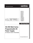
5.5.1
Output channel characteristics
P=60W
0
0
6
10
11
10
9
8
7
6
5
4
3
2
1
CURRENT I (A)
11
10
9
8
7
6
5
4
3
2
1
CURRENT I (A)
CURRENT I (A)
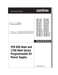
PM2811/12/13
Each individual output channel can supply power according to its output
characteristic. Figure 5.5.1 below gives you information about the three possible
output channel characteristics. The power output is rated and limited according to
the formula: P (power) = U (voltage) x I (current).
P=60W
0
20
30
40 50 60 70
VOLTAGE U (V)
0
12
10
11
10
9
8
7
6
5
4
3
2
1
P=120W
0
20
30
40 50 60 70
VOLTAGE U (V)
0
12
10
20
30
40 50 60 70
VOLTAGE U (V)
ST5835
30V/10A/60W
60V/5A/60W
60V/10A/120W
Figure 5.5.1 Output Channel Characteristics
As an example look at the 30V/10A/60W output channel ratings:
• For voltages from 0 to 6V the current can increase to its maximum of 10A. For
voltages > 6 to 30V, the current can increase to its maximum along the stated
curve, e.g., 20V gives maximum of 3A.
• For currents from 0 to 2A the maximum voltage can be 30V. For currents > 2
to 10A, the voltage can increase to its maximum along the stated curve, e.g.,
5A gives a maximum of 12V.
5-8
Users Manual
PM2831/32
The following characteristic shows the work area of the output parameters. The
linear system power supplies PM2831 and PM2832 can source as well as sink
currents. There is, however, only one setting for current. When the power supply
is used as a load, the value of the sink current will always track the positive
setting.
+V
−Pmax
Pmax
Vmax
Constant voltage as well
as constant current mode
possible.
Only constant current
mode possible.
1.5V
−A
−Imax
ST6878
0
Imax
+A
Figure 5.5.2 Output channel characteristics
This characteristic shows that the power supply will output maximum power (only)
at Vmax @ Imax and will absorb maximum power at Vmax @ -Imax.
Overcurrent protection, if enabled, will also work for sink currents that exceed Iset.
Overvoltage protection will work also for voltages applied from an external source,
if the voltage from this source exceeds the overvoltage protection level.
Using your Programmable Power Supply
5-9
Current sink characteristics PM2831/32
The following figure gives an example that shows the sink characteristics of the
power supply. The power supply is used as a constant current load for an external
source, where the sink capability of the power supply is demonstrated.
Overvoltage protection is set to the maximum level and overcurrent protection is
disabled.
V
Vsource (External Constant
Voltage Source)
Vsource −0.6V+0.15V
Vsource −0.6V
−A
0
Iset_load
+A
ST6841
Figure 5.5.3 Current sink characteristics
The power supply and the external source (this may be another power supply) are
set to the same output voltage: Vsource. There is no current flow yet.
The current settings are: Iset_source > Iset_load.
The voltage setting of the load is gradually decreased by pressing the -V+ key. The
change of the actual voltage setting is not visible on the display, because the display
will show the constant voltage applied by the external source. But the voltage
setting of the power supply can be made visible at any moment by pressing the V
key. When the setting approaches Vsource - 0.6V, the power supply switches to the
constant current (CC) mode at the level of -Iset_load. In this situation the negative
current of the power supply tracks the programmed (positive) value Iset_load.
The voltage can be raised by pressing the -V+ key. When the setting approaches
Vsource - 0.6V + 0.15V, the power supply will exit constant current mode and return
to the constant voltage mode @ 0A.
5 - 10
5.5.2
Users Manual
Local and remote sensing
All models have the ability to sense the output voltage locally or remotely. The
wires between an output channel and the connected load have a resistance,
which causes a voltage drop. If the voltage drop is not acceptable, remote sensing
must be applied.
1
2
R lead
+S
+V
V
S
R load
1
2
R lead
ST5836
Figure 5.5.4 Voltage drop due to Wire Resistance Rlead.
The formula to calculate the voltage drop is Vdrop = Iload x Rlead:
• Vdrop = the total voltage drop of both wires
• Iload = the current through the load
• Rlead = the total resistance of both wires between the power supply and the
load
Figures 5.5.5 and 5.5.6 show the difference between a local and remote
connection has been indicated.
CAUTION:
To prevent shock or short-circuit you must set the power supply to
the standby mode before making any changes in the output
channel connections or you must disable the output channel (only
possible for multiple output models).
All the models and their output channels have the same terminal block (see the
following diagram). This means that all output channels have the local or remote
sensing feature. The load is supplied with power (voltage and/or current) through
the output terminals -V and + V. The readback of the output voltage is done
through the input terminals -S and + S.
Using your Programmable Power Supply
5 - 11
Local sensing mode:
Local sensing is used when the voltage across the load does not need to
compensate for the voltage drop across the load leads. This may be the case
when the following conditions exist:
•
Short wires between the output channel and the load (R load > Rlead).
•
Low current through the connected load.
+S
+V
V
S
R load
ST5837
Figure 5.5.5 Connection of a Load in the Local Sense Mode
Remote sensing mode:
Remote sensing is used if the voltage accross the load must exactly match the
programmed value; remote sensing will namely compensate for the voltage drop
accross the load leads. This mode will be useful when the following conditions exist:
•
Long leads between the output channel and the load (Rload ≤ Rlead).
•
High current through the connected load.
+S
+V
V
S
R load
ST5847
Figure 5.5.6 Connection of a Load in the Remote Sense Mode
Note that with remote sensing, the readback of the load voltage is monitored at
the load terminals. When using the remote sensing mode, it is necessary to twist
the sense wires to avoid disturbance and noise pickup in the sense input
terminals, which might cause instability of the output.
During remote sensing, the power supply can compensate for voltage drops up to
a specified minimum value. This is called the remote sense capability (see the
Reference Manual, Appendix A). When the voltage drop exceeds this value,
sense FAIL may occur. The output voltage and current are then reduced to zero
and the display shows the FAIL message.
5 - 12
Users Manual
When the sense leads are disconnected, the power supply goes into the local sense
mode, as the V and S terminals are internally interconnected via resistors. Yet you are
strongly recommended to interconnect the V and S terminals with the straps if you
use the local sense mode, as open sense inputs are sensitive to noise. Moreover, the
output specifications are not guaranteed when the sense terminals are open.
Output modules with low voltage ratings may have less sense capability for output
voltages in the upper part of the voltage range, e.g. the 8V/15A module for the
sense range from 4V to 8V (see the Reference Manual, Appendix A).
For power supplies with a Front Connection Unit, the sense capability is reduced
with about 5mV/A per load lead.
Using your Programmable Power Supply
5.5.3
5 - 13
Constant voltage or constant current source
Your power supply has been designed according to the automatic crossover
principle. This means that each output channel will operate in the Constant
Voltage (CV) mode or in the Constant Current CC mode, depending on:
• the programmed output voltage Vset and current Iset
• the resistance (impedance) of the load Rload, connected to the output channel
For a given Vset and Iset, an output channel is either:
Vset
in the CV mode if Rload >
Vset
or in the CC mode if Rload <
Iset
.
Iset
In the CV mode the output is a constant voltage, so the current through the load
depends on the load resistance (Rload).
In the CC mode the output is a constant current, so the voltage across the load
depends on the load resistance (Rload).
The following picture shows when the output channel goes into the CV or into the
CC mode of operation, when connected to a variable resistor Rload.
Voltage
R=∞ (open circuit)
Rc= Vset
Iset
Rload >Rc
(crossover point)
CV
V(set)
CC
Rload <Rc
R= 0 (short circuit)
I(set)
Current
ST5848
Figure 5.5.7 Power Output Crossover Point
If Rload increases (Rload > Rc), the output channel goes into the CV mode,
reducing the current through the load.
If Rload decreases (Rload < Rc), the output channel goes into the CC mode,
reducing the voltage across the load.
5 - 14
Users Manual
To protect the load against excessive currents, the maximum current Iset can be
programmed, and the overcurrent protection can be enabled.
To protect the load against excessive voltages, the overvoltage protection level
OVPset can be programmed.
LIMITATIONS
The output power is limited by:
• the output specific maximum power Pmax, according to the formula:
Iset x Vset <= Pmax
RESTRICTIONS
The output voltage is restricted by:
• the output specific maximum voltage, or
• the overvoltage protection level OVPset
Note:
When the output voltage exceeds the overvoltage protection level,
both the output voltage and current are reduced to zero.
The output current is restricted by:
• the output specific maximum current, or
• the programmed maximum current level Iset
Note:
If the overcurrent protection has been enabled and the output current
exceeds the maximum current (Iset), the output voltage and current
are reduced to zero.
If the overcurrent protection has been disabled, the output current
will be kept at its maximum (Iset). The consequence is that the output
voltage will not reach its programmed value (Vset), and the output
channel will go into the CC mode.
Using your Programmable Power Supply
5 - 15
Example for a variable load resistance:
power
+
output
+
Vset
OVPset
Iset
load
-
Required:
Vset = Voltage programmed
= Current programmed
Iset
Rload = 2Ω to 20Ω (variable)
The Vset and Iset parameter have been coupled for the selected
output channel.
• ISet = 1A
Programmed current becomes 1A.
• Vset = 8V
Programmed voltage becomes 8V.
The crossover point resistance Rc = Vset / Iset = 8Ω.
• If Rload increases from 8Ω to 16Ω, then Rload > Rc, so the output channel goes
into the CV mode (refer to figure 5.5.7). This means that Vload = 8V and
Iload becomes 8V/16Ω = 0.5A.
• If Rload decreases from 8Ω to 4Ω, then Rload < Rc, so the output channel goes
into the CC mode (refer to figure 5.5.7). This means that Iload = 1A and Vload
becomes 1A x 4Ω = 4V.
Example for a fixed load resistance:
power
+
output
Required:
+
Vset
OVPset
Iset
load
Vset
= Voltage programmed
OVPset = OverVoltage programmed
= Current programmed
Iset
- Fixed load resistance Rload = 10Ω.
- Overcurrent protection disabled (OCP DIS).
- The Vset and Iset parameter have not been coupled.
5 - 16
Users Manual
• Iset = 0.5A
Maximum current through the load becomes 0.5A.
• OVPset = 7V
Overvoltage protection trip level becomes 7V.
Sequentially the voltages 2V, 4V, 6V, and 8V will be programmed:
• Vset = 2V
Iload = Vset / Rload =2V/10Ω = 0.2A.
The output channel stays in the CV mode.
• Vset = 4V
Iload = Vset / Rload = 4V/10Ω = 0.4A.
The output channel stays in the CV mode.
• Vset = 6V
Iload = Vset / Rload = 6V/10Ω = 0.6A. However, the maximum
output current (0.5A) is going to be exceeded. Therefore, the
current through the load becomes 0.5A and the voltage
across the load is limited at 0.5A x 10Ω = 5V.
The output channel goes into the CC mode.
• Iset = 1A
The maximum current through the load becomes 1A.
Iload = Vset / Rload = 6V/10Ω = 0.6A. The voltage across the
load becomes 0.6A x 10Ω = 6V.
The output channel goes back into the CV mode.
• Vset = 8V
Now the overvoltage protection trip level OVPset (7V) is going
to be exceeded. This will activate the overvoltage protection
circuitry, so the output voltage and current will be reduced to
zero. Also the message OVERVOLTAGE will be displayed.
• OVPset = 9V
The overvoltage protection trip level becomes 9V.
• RESET
The overvoltage protection circuitry is reset, and the voltage
across the load becomes 8V.
Iload = Vset / Rload = 8V/10Ω = 0.8A.
The output channel remains in the CV mode.
Using your Programmable Power Supply
5 - 17
Local control (in CV or CC mode):
The voltage Vset can be set using the V key and the numeric input keys.
Example:
Press the V key to start the voltage setting.
Press the keys 3, . (dot), 4 and ENTER to enter the setting of 3.4V.
The current Iset can be set using the I key and the numeric input keys.
Example:
Press the I key to start the current setting.
Press the keys 0, dot (.), 2, 3 and ENTER to enter the setting of 0.23A.
The overvoltage protection level OVPset can be set using the OVP key and
the numeric input keys.
Example:
Press the OVP key to initiate the overvoltage setting.
Press the keys 7 and ENTER to enter the overvoltage setting of 7V.
OCP EN
The overcurrent protection can be enabled/disabled using the OCP
DIS key.
Example:
Press the OCP EN/OCP DIS key.
IF OCP was enabled THEN OCP is disabled
ELSE OCP is enabled.
IF OCP has been enabled, the annunciator above the text OCP
will be displayed.
EN
An overcurrent or overvoltage trip protection can be reset by pressing the
RESET key.
The display of OVERCURRENT or OVERVOLTAGE will also
disappear.
In the CV mode, the annunciator above the text CV will be displayed.
In the CC mode, the annunciator above the text CC will be displayed.
5 - 18
Users Manual
Remote control (in CV or CC mode):
The voltage Vset can be programmed by the SOURCE subsystem command:
[:SOURce]:VOLTage[:LEVel][:IMMediate][:AMPLitude]
The voltage Vset can be requested by the SOURCE subsystem query:
[:SOURce]:VOLTage[:LEVel][:IMMediate][:AMPLitude]?
The output voltage can be read back by the MEASURE subsystem query:
:MEASure[:SCALar]:VOLTage[:DC]?
Example:
Send → :VOLT 3.4
Set 3.4V.
Send → :VOLT?
Send request voltage setting.
Read voltage setting.
Read ← set_voltage
Display voltage setting.
Print set_voltage
Send → :MEAS:VOLT?
Send readback query.
Read output voltage.
Read ← meas_voltage
Display measured voltage.
Print meas_voltage
The current Iset can be programmed by the SOURCE subsystem command:
[:SOURce]:CURRent[:LEVel][:IMMediate][:AMPLitude]
The current Iset can be requested by the SOURCE subsystem query:
[:SOURce]:CURRent[:LEVel][:IMMediate][:AMPLitude]?
The output current can be read back by the MEASURE subsystem query:
:MEASure[:SCALar]:CURRent[:DC]?
Example:
Send → :CURR 0.23
Set 0.23A.
Send → :CURR?
Send request current setting.
Read ← set_current
Read current setting.
Print set_current
Display current setting.
Send → :MEAS:CURR?
Send readback query.
Read ← meas_current
Read output current.
Print meas_current
Display measured current.
Using your Programmable Power Supply
5 - 19
The overvoltage protection level OVPset can be programmed by the SOURCE
subsystem command: [:SOURce]:VOLTage:PROTection[:LEVel]
The overvoltage protection level OVPset can be requested by the SOURCE
subsystem query:
[:SOURce]:VOLTage:PROTection[:LEVel]?
Example:
Send → :VOLT:PROT 7
Set 7V protection level.
Send → :MEAS:PROT?
Send readback query.
Read overvoltage protection level.
Read ← meas_over_voltage
Display overvoltage protection level.
Print meas_over_voltage
Theovercurrentprotectioncanbeenabled/disabledbytheSOURCEsubsystemcommand:
[:SOURce]:CURRent:PROTection:STATe
Example:
Send → :CURR:PROT:STAT ON Enable overcurrent protection.
Send → :CURR:PROT:STAT OFF Disable overcurrent protection.
5.5.4
Store/recall function
Your programmable power supply has a recall memory (battery backed up) to be
used for storing and recalling voltage and current settings of all output channels.
The battery back up feature ensures that the stored values will be kept in memory
during power-off. The recall memory consists of 999 addresses, numbered from
1 to 999. A recall memory address contains space for the voltage and current
setting of all available output channels.
output channel 3
output channel 2
output channel 1
address 1
voltage 1
current 1
address 2
voltage 2
current 2
address 998
voltage 998
current 998
address 999
voltage 999
current 999
5 - 20
Users Manual
At delivery the contents of all addresses are set to their minimum value. When an
address has been filled, its contents can be recalled, so that the settings become
actual. The actual settings can be updated in OPERATE and STANDBY modes,
but they are only active in the OPERATE mode. When the power supply is in the
STANDBY mode, the actual settings will become active as soon as the OPERATE
mode is entered.
Note:
To remember which locations have been programmed and which have
not, keep a record (such as the following) of which locations have been
used.
MEMORY
OUTPUT CHANNEL 1
OUTPUT CHANNEL 2
ADDRESS
VOLTAGE
CURRENT
VOLTAGE
CURRENT
01
02
03
04
2.0
1.9
1.8
etc.
0.00
0.10
0.20
etc.
5.9
5.8
5.7
etc.
0.90
0.80
0.70
etc.
Local control (store/recall):
The voltage Vset can be set using the V key and the numeric input keys.
V + key in the OPERATE mode.
The output voltage can be adjusted using the
The current Iset can be set using the
I
key and the numeric input keys.
The output current can be adjusted using the
I +
key in the OPERATE mode.
The actual voltage/current setting can be stored using the
STORE
The actual voltage/current setting can be recalled using the
key.
RECALL
key.
Example:
• REQUIREMENTS : Fill the memory address 23 with 5V/0.3A and the
memory addresses 33, 34, and 35 with, respectively,
4V/1A, 3V/1A and 2V/1A for output channel 1.
• SOLUTION:
OPR
Press STBY
to make the STANDBY mode active.
For multiple output units, press
SELECT
a number of times until output
channel 1 has been selected (see indication 1 on the display).
Press
V
Press
I
Press
STORE
to set the actual voltage at 5V.
5
ENTER
3
ENTER
to set the actual current at 0.3A.
2
3
ENTER
to store the 5V and 0.3A at memory address 23.
Using your Programmable Power Supply
5 - 21
Press
V
4
ENTER
to set the actual voltage at 4V.
Press
I
1
ENTER
to set the actual current at 1A.
Press
STORE
3
3
Press
V
3
ENTER
Press
STORE
3
4
Press
V
2
ENTER
Press
STORE
3
5
ENTER
to store the 4V and 1A at memory address 33.
to set the actual voltage at 3V.
ENTER
to store the 3V and 1A at memory address 34.
to set the actual voltage at 2V.
ENTER
to store the 2V and 1A at memory address 35.
Verify the programmed memory addresses, using
input keys plus
V
Press
3
I
RECALL
2
and
ENTER
I
RECALL
and the numeric
keys, e.g.:
. Press
V
to verify the voltage of 5V. Press
to verify the current of 0.3A.
Remote control (store/recall):
The recall memory voltage can be programmed using the
[:SOURce]:LIST:VOLTage command.
The recall memory current can be programmed using the
[:SOURce]:LIST:CURRent command.
The actual memory address index (1 to 999) can be selected using the
[:SOURce]:LIST:INDex[:NSELect] command.
Example:
• REQUIREMENTS : Fill the memory address 23 with 5V/0.3A and the
memory addresses 33, 34, and 35 with, respectively,
4V/1A, 3V/1A and 2V/1A for output channel 1.
• SOLUTION:
Send → :INST:STAT OFF
STANDBY mode active.
Send → :INST:NSEL 1
Output channel 1 selected.
Send → :LIST:IND 23
Address 23 selected.
Send → :LIST:VOLT 5
Send → :LIST:CURR 0.3
5V/0.3A stored at address 23.
Send → :LIST:IND 33
Address 33 selected.
Send → :LIST:VOLT 4,3,2
4V, 3V, and 2V, stored at respectively, the
addresses 33, 34, and 35.
Send → :LIST:CURR 1,1,1
1A stored at the addresses 33, 34, and 35.
5 - 22
5.5.5
Users Manual
Step functions
When a list of memory addresses has been filled with voltage and current
settings, it can be used in one of the following ways:
1) AUTO_STEP OFF:
This will invoke the manual step function, i.e., the next step is initiated by
the operator. For instance by manually stepping through a list of
predefined voltages and currents, a test pattern of voltage and current
settings will be generated. The manual stepping will be executed for all
enabled output channels. Refer to section "Manual step function" on this
page.
2) AUTO_STEP ON:
This will invoke the automatic step function, i.e. the next step is initiated
when the interval time has expired. For instance by automatically stepping
through a list of sequential voltages and currents, a voltage/current ramp
function will be executed. The start and stop address of the sequential list
and the interval time between two consecutive steps can be programmed.
Stepping can be done in one of the following ways:
3) CONTINUOUS_STEP OFF:
The predefined sequence of memory addresses is executed only once.
4) CONTINUOUS_STEP ON:
The predefined sequence of memory addresses is executed continuously,
i.e., repeatedly from start to stop address.
Stepping will be executed for all enabled output channels. Refer to section
"Automatic step function" on the next page.
Manual step function:
The manual step function can be executed locally, using the
STEP
key.
The AUTO_STEP function can be set ON or OFF via the STEP MENU under the
AUX
key.
Example:
• REQUIREMENTS :
Step manually through the predefined list of voltage and current settings,
stored at the memory addresses 20 to 40. The voltage and current settings
must be output for channel 1. Output channel 2 must be disabled.
Using your Programmable Power Supply
•
SOLUTION:
Press AUX
5 - 23
to enter the STEP submenu.
ENTER
Check that the AUTO STEP is OFF, or press the OFF (0) key to set the
AUTO STEP function off.
Press
ENTER
to leave the STEP submenu.
Press
SELECT
(only for multiple output models) to select output channel 1.
Press
ENABLE
DISABLE
to enable output channel 1.
Press
SELECT
(only for multiple output models) to select output channel 2.
Press
ENABLE
DISABLE
to disable output channel 2.
Press
SELECT
as many times as necessary to select output channel 1 again.
Press
OPR
STBY
Press
STEP
Press
2
to make the OPERATE mode active.
to enter the step mode.
0
ENTER
to select start address 20 of the list.
The display reads:
LOOP:
Press
1
S T E P
2 0
. . . . . . .
if you want to see the actual voltage on output
V
channel 1 at the memory address as indicated on the display.
Press
if you want to see the actual current from output
I
channel 1 at the memory address as indicated on the display.
Press
STEP
to select the next memory address of the list.
Repeat this loop until step 40 is made active.
ENDLOOP
Press
SELECT
to select output channel 2.
The display reads:
Press
2
S T E P
4 0 D I S
to leave the step mode.
Remark: When the next step is executed, the next voltage and current
setting in the list is made active and output on the selected
channel.
Automatic step function
Local control (automatic stepping):
The AUTO STEP function, the CONTINUOUS STEP function, the step interval
time, the START address, and the STOP address can be set via the
The automatic step function can be started by pressing the
STEP
key.
AUX
key.
5 - 24
Users Manual
Example:
• REQUIREMENTS:
Step automatically through the predefined list of voltage and current
settings stored at the memory addresses 20 to 40. When the end of the list
is reached, it must be started again at the beginning. The next voltage and
current setting must be output for channel 1 at an interval time of 5
seconds.
•
SOLUTION:
Press AUX
Press
1
Press
AUX
Press
5
Press
AUX
Press
1
ENTER
to enter the STEP submenu.
to set the AUTO STEP function on.
to set the TIME INTerval function.
ENTER
to set the interval time at 5 seconds.
to set the CONTINUOUS step function.
to set the CONTINUOUS step function on.
Press
AUX
Press
2
to set the START AT function.
0
ENTER
to set the start address of the sequence list at 20.
Press
AUX
Press
4
to set the STOP AT function.
Press
ENTER
to leave the AUX menu.
Press
SELECT
(only for multiple output models) to select output channel 1.
Press
to enable output channel 1.
Press
ENABLE
DISABLE
OPR
STBY
Press
STEP
Press
2
0
ENTER
to make the OPERATE mode active.
to enter the step mode.
0
to select start address 20 of the list.
The display reads :
Press
•
•
to set the stop address of the sequence list at 40.
ENTER
1
S T E P
T O
2 0
to initiate the automatic stepping.
Check that the memory address is automatically incremented every
5 seconds on the display.
Exit the automatic stepping by pressing the (backspace) key. The last
recalled voltage and current setting remain active.
Using your Programmable Power Supply
5 - 25
Remote control (automatic stepping):
The actual memory address index (1 to 999) can be selected using the
[:SOURce]:LIST:INDex[:NSELect] command. The selected memory address can
be requested by means of the [:SOURce]:LIST:INDex[:NSELect]? query.
A sequence list of memory addresses can be defined using the
[:SOURce]:LIST:SEQuence:STARt and [:SOURce]:LIST:SEQuence:STOP
commands.
A sequence list of memory addresses can be reported using the
[:SOURce]:LIST:SEQuence:STARt? and [:SOURce]:LIST:SEQuence:STOP?
queries.
The length of a sequence list, i.e., the number of voltage and current points, can
be requested by the [:SOURce]:LIST:VOLTage:POINts? and
[:SOURce]:LIST:CURRent:POINts? queries.
The step interval time can be defined by the [:SOURce]:LIST:TIMer command and
can be requested by the [:SOURce]:LIST:TIMer? query.
The source of the next step in the sequence list (the step trigger) can be defined
and requested by the [:SOURce]:LIST:SOURce command, respectively the
[:SOURce]:LIST:SOURce? query. The following sources are possible:
• If source = TIMer, the internal timer of the power supply is used to count
the step interval time.
• If source = EXTernal or BUS, the active trigger source depends on whether
the START line of the trigger bus at the rear of the power supply is active
or not. If active, step pulses from the external STEP input will cause the
next step to be performed. If not active, the next step will be performed
after the TRG command or after the GET trigger command.
*
The execution of a sequence list can be started using the :INITiate[:IMMediate]
command. The first address is the START address, and the last address is the
STOP address.
A sequence list can be executed continuously by means of the
:INITiate:CONTinuous command.
The execution of a sequence list can be stopped by means of the :ABORt
command. If the execution is stopped, the last recalled voltage and current setting
remain active.
5 - 26
Users Manual
Example:
• REQUIREMENTS:
Step automatically through the predefined list of voltage and current
settings, stored at the memory addresses 20 through 40. When the end of
the list is reached, it must be started again at the beginning. The next
voltage and current setting must be output for channel 1 at an interval time
of 5 seconds.
•
SOLUTION:
Send → :LIST:SOUR TIM
The next step is automatically initiated by
the internal timer.
Send → :LIST:TIM 5.0
Set the interval time at 5 seconds.
Send → :LIST:SEQ:START 20 Set the start address of the sequence list
at 20.
Send → :LIST:SEQ:STOP 40 Set the stop address of the sequence list
at 40.
Send → :INST:NSEL 1
Select output channel 1.
Send → :OUTP:STAT ON
Enable output channel 1.
Send → :INST:STAT ON
Make OPERATE mode active.
Send → :INIT:CONT ON
Set the CONTINUOUS step function on.
Send → :INIT
Initiate the automatic stepping.
.
Check the display of the power supply to verify that the memory address
is automatically incremented every 5 seconds.
.
Send → :ABORT
Exit the automatic stepping.
Check that the last recalled voltage and current setting remain active.
External step functions
There are three SMB connectors at the rear: START, STEP, and READY.
The modes and functions of the connectors are shown in the following table.
NAME
MODE
FUNCTION
START
input
Enables stepping via the STEP input.
STEP
input
Executes the next step.
READY
output
Indicates whether a step is finished (ready for
the next step).
Using your Programmable Power Supply
5 - 27
There is a standard GPIB interface connector at the rear. The GPIB interface
software supports complete trigger capability.
If the trigger source = TIMer, the internal timer of the power supply is used to count
the interval time between two consecutive steps.
If the trigger source = EXTernal or BUS, the active trigger source depends on
whether or not the START line of the trigger bus at the rear is active.
EXTERNAL STEPPING (via the trigger bus)
If the START line is active (LOW), step pulses from the external STEP input
line will cause the next step to be performed.
EXTERNAL STEPPING (via the GPIB)
If the START line is not active (HIGH), the next step will be performed on the
receipt of the *TRG command or the GET code via the GPIB.
Note:
LOW = 0 to 0.8V and HIGH = 2 to 5V
Trigger bus control:
External stepping via the trigger bus can be done in two ways:
1) In the synchronous mode:
In this mode all three bus signal lines have their own functions.
2) In the asynchronous mode:
In this mode the READY line is externally connected to the START line.
To control the recall memory via the trigger bus, the STEP mode may not be
automatic, and the START input line must be pulled LOW. This will enable the
STEP line to trigger the next step to be executed (external triggering). Pulling the
START line LOW will also disable the manual STEP key.
When enabled, a STEP pulse will trigger the step mechanism. The leading edge
of the STEP pulse makes the READY line active (LOW) within 100 nanoseconds.
The READY line will be released when the internal processing is finished and the
STEP line is HIGH. The internal processing time does not include the
reprogramming delay time. It is the responsibility of the user to choose a STEP
rate that is not too high for the power supply and its load condition, so that the
output can settle within the STEP time.
Note:
STEP pulses, received while the READY line is low, will be ignored.
5 - 28
Users Manual
GPIB control:
GPIB control can only be done in the remote mode of operation. An external
trigger can be programmed in the following ways:
•
Send → TRG
By sending the common command TRG to the power
supply.
•
Send → GET
By sending the GET (Group Execute Trigger) code over
the GPIB interface.
*
*
5.6 ADVANCED USE
This section describes how to connect several output channels (with the same
ratings) to obtain higher output power through a connected load.
To increase the total output current through a connected load, the output channels
must be connected in parallel. Refer to section 5.6.1.
To increase the total output voltage over a connected load, the output channels
must be connected in series. Refer to section 5.6.2.
This section also describes the way to connect more than one load to an output
channel (multiple loads). Refer to section 5.6.3.
CAUTION: Only output channels with equivalent voltage and current ratings may
be connected in series or in parallel to prevent that the channel with
the lowest output ratings will be damaged.
Using your Programmable Power Supply
5 - 29
5.6.1
Parallel connection of output channels
Note:
For the PM2812 and PM2813 you can face a number of restrictions
when connecting output channels in parallel to a load. Please read
Appendix D to get more information of parallel connection of output
channels fore these instruments.
For the PM2831 and PM2832, parallel connection of output channels is
only possible in the source (non-sink) mode
Connecting output channels in parallel provides a greater current capability than
can be obtained from a single output channel. In principle, you can put more than
two output channels in parallel.
Output channels in parallel configurations can operate in either Constant Voltage
(CV) or in Constant Current (CC).
When channels are connected in parallel with the intention of increasing the
current capability, it is advised that you set all channels to the same voltage. When
the channels have the same power characteristics, set them to the same current
value.
In general, you can handle the following procedure.
•
•
Set the power supply to STANDBY before making any connections.
Connect the channels in parallel.
If a constant voltage is required accross the load, proceed as follows.
•
•
•
•
Program the voltage setting of all channels equal to the constant voltage
required.
Calculate the maximum current needed for the load (Imax). Count with the
minimum value of Rload.
Program the current setting of the individual channels so that the sum of the
values is equal to Imax.
Now you may set the power supply to the operate mode.
If a constant current is required through the load, proceed as follows.
•
•
•
•
Program the current setting of the individual channels so that the sum of the
values is equal to the value of the constant current required.
Calculate the maximum voltage needed to supply the constant current. Count
with the maximum value of Rload.
Program the voltage setting of all channels equal to the maximum voltage
needed.
Now you may set the power supply to the operate mode.
5 - 30
Users Manual
If neither constant voltage nor constant current is required, you may program
typical values as well.
There are two ways of sensing the load when connecting output channels in
parallel: local sensing and remote sensing.
Local sensing (outputs in parallel):
Connecting the load wires directly to the +V and -V terminals of output channel 2
keeps the number and the total length of the load wires to a minimum. The
following diagram shows the wiring scheme.
+S
+V
OUTPUT 1
V
S
TWISTED
PAIR
+S
OUTPUT 2
+V
+
LOAD
V
S
ST5872
Figure 5.6.1 Local Sensing with Two Outputs in Parallel
CAUTION: To prevent noise pickup, twist the sense wires and shield them from
the environment.
Using your Programmable Power Supply
5 - 31
Remote sensing (outputs in parallel):
The sense wires are connected from the load to the +S and -S terminals of output
channel 2. This compensates for the voltage drop in the wires from the load to the
+V and -V terminals. The following diagram shows the wiring scheme.
+S
+V
OUTPUT 1
V
S
TWISTED
PAIR
+S
+V
OUTPUT 2
+
LOAD
V
S
ST5873
Figure 5.6.2 Remote Sensing with Two Outputs in Parallel
CAUTION: To prevent noise pickup, twist the sense wires and shield them from
the environment.
5 - 32
5.6.2
Users Manual
Serial connection of output channels
Connecting output channels in series provides a greater voltage capability than
can be obtained from a single output channel. In principle, you can put more than
two output channels in series. However, there is the limitation that the total
maximum voltage of each terminal may not exceed 240V with respect to the
ground.
Output channels in serial configurations can operate in either Constant Voltage
(CV) or in Constant Current (CC).
CV OPERATION
For CV operation all output channels must be in the CV mode. Program the
current setting of all output channels to the desired current limit point. Then
program the voltage setting of each output channel, so that the sum of all
voltages equals the total desired operating voltage. The simplest way to
accomplish this is to program each output channel to an equal part of the total
desired operating voltage, e.g., three output channel settings of 25 V in series
provide 75 V.
CC OPERATION
For CC operation the current setting of each output channel must be
programmed to the desired operating current. The sum of the voltage settings
determines the voltage limit points. As an example, consider two output
channels in series (refer also to section 5.6.2.1). Program the voltage setting
of both output channels to one half of the total voltage limit point. At load
voltages < 1/2 of the total voltage limit point, one output channel will operate
in the CC mode. At load voltages > 1/2 of the total voltage limit point, the output
channel that was in the CC mode will change to the CV mode, while the other
output channel will regulate the current in the CC mode and provide the
balance of the voltage required by the load.
Note that the total voltage over the load is the sum of the individual readback
output voltages, provided the load voltage < 1/2 of total voltage limit point.
WARNING:
To guarantee the safe use of the power supply, the total
maximum voltage at each terminal must not exceed 240V with
respect to ground.
There are two ways of sensing the load when connecting output channels in
series, i.e., local sensing and remote sensing.
Using your Programmable Power Supply
5 - 33
Local sensing (outputs in series):
Connect the load wires to the +V terminal of output channel 1 and the -V terminal
of output channel 2, and interconnect the -V terminal of output channel 1 and the
+V terminal of output channel 2. Connecting the +S of output channel 2 to the -S
of output channel 1, while removing the local sense jumper between +S and +V
of output channel 2, will compensate for the voltage drop across the wires from
output channel 2 to output channel 1. The following diagram shows the wiring
scheme.
+S
+V
OUTPUT 1
V
S
+
LOAD
+S
+V
OUTPUT 2
V
S
ST5874
Figure 5.6.3 Local Sensing with Two Outputs in Series
5 - 34
Users Manual
Remote sensing (outputs in series):
Connecting extra sense wires from the load to the +S terminal of output channel
1 and the -S terminal of output channel 2 compensates for the voltage drop in the
wires from the load to the +V and -V terminals. Connecting the +S of output
channel 2 to the -S of output channel 1, while removing the local sense jumper
between +S and +V of output channel 2, will compensate for the voltage drop
across the wires from output channel 2 to output channel 1.The following diagram
shows the wiring scheme.
+S
+V
OUTPUT 1
V
S
+
LOAD
+S
OUTPUT 2
+V
V
S
ST5875
Figure 5.6.4 Remote Sensing with Two Outputs in Series
CAUTION: To prevent noise pickup, twist the sense wires and shield them from
the environment.
Using your Programmable Power Supply
5.6.3
5 - 35
Parallel connection of loads
If more than one load is connected to an output channel, use separate wires to
connect each load. This minimizes mutual coupling effects and takes full
advantage of the power supply’s low output impedance. Each pair of wires should
be as short as possible to reduce wire inductance and noise pickup. The loads
must be connected in parallel, not in series, so that loads are not mutually
influenced by load fluctuations.
It is advised to use a pair of DC distribution terminals (DT) not located at the
output channel terminals.
Note:
In principle, there is no restriction about the number of loads that can be
connected. Remote voltage sensing is recommended if one load is more
sensitive than the other(s); therefore, sense directly at the most sensitive
load.
Local sensing (loads in parallel):
The following diagram shows the wiring scheme.
+
+S
LOAD
+V
DT+
V
DT
S
+
LOAD
ST5866
Figure 5.6.5 Local Sensing withTwo Loads in Parallel
If local sensing is used, locate the distribution terminals (DT) as near as possible
to the output channel terminals.
5 - 36
Users Manual
Remote sensing (loads in parallel):
The following diagram shows the wiring scheme.
+
+S
LOAD
+V
DT+
V
DT
S
+
LOAD
ST5867
Figure 5.6.6 Remote Sensing withTwo Loads in Parallel
If remote sensing is used, locate the distribution terminals (DT) as near as
possible to the load terminals.
CAUTION: To prevent noise pickup, twist the sense wires and shield them from
the environment.
5.6.4
Tips for Remote Sensing Applications
Prevent Output Noise
It is advised to twist or to shield the sense leads to minimize the pickup of
envirionmental noise. If the sense leads are twisted, run them parallel and close
to the load leads. In environments with heavy noise, it may be necessary to shield
the sense leads. Connect the shield to ground at the power supply end only.
Prevent Instability
The impedance of the load leads together with the capacitance of the load can form
a filter , which may cause a phase shift in the sense feedback loop. This can cause
instability or even oscillations, which must be prevented. If there is doubt about the
stability of the output, you can check this with an oscilloscope. There are no simple
rules to prevent instability for all circumstances, but the following guidelines are
valid most often:
1. Use short leads with low resistance for the load and the sense connections.
2. Twist the load leads together to minimize additional inductance.
3. Twist the sense leads together (or shield them) to minimize interference with
the environment.
4. Keep the load capacitance as small as possible.
Accessories
A-1
APPENDIX A ACCESSORIES
A.1 Supplied with the instrument
•
Reference Manual English
:
4822 872 00827
•
Operation Manual English
Operation Manual German
Operation Manual French
:
:
:
4822 872 00824, or
4822 872 00825, or
4822 872 00826
•
Power Cord EURO
Power Cord SWISS
Power Cord UK
Power Cord USA
:
:
:
:
5322 321 23297, or
5322 321 10679, or
5322 321 10681, or
5322 321 10644
•
•
Two spare fuses
Two mounting brackets (not with PM2811)
A.2 Optional
The following accessories can be ordered via your local Fluke Sales and Service
Center.
•
19” Rack mount (with other 19” units)
:
PM9280/03
•
•
Service Manual PM2811/12/13
Service manual PM2831/32
:
:
4822 872 85005
4822 872 85004
•
Standard Commands for
Programmable Instruments
:
4822 872 80194
A-2
Users Manual
SCPI Conformance Information
B-1
APPENDIX B
SCPI CONFORMANCE INFORMATION
This instrument complies to the SCPI standard version 1993.0. The following
classes of commands and queries have been implemented:
B.1 IEEE 488.2-1987
*CLS
*ESE
*ESE?
*ESR?
*IDN?
*OPC
*OPC?
*PSC
*PSC?
*RCL
*RST
*SAV
*SRE
*SRE?
*STB?
*TRG
*TST?
*WAI
B.2 SCPI Std 1993.0 Confirmed
:ABORT
:CALIBRATION:STATE
:CALIBRATION:STATE?
:CALIBRATION:VALUE
:CALIBRATION:AUTO
:DISPLAY:ENABLE
:DISPLAY:ENABLE?
:DISPLAY:CONTRAST
:DISPLAY:CONTRAST?
B-2
Users Manual
:DISPLAY:WINDOW:TEXT:DATA
:DISPLAY:WINDOW:TEXT:DATA?
:INITIATE:IMMEDIATE
:INITIATE:CONTINUOUS
:INITIATE:CONTINUOUS?
:INSTRUMENT:SELECT
:INSTRUMENT:SELECT?
:INSTRUMENT:NSELECT
:INSTRUMENT:NSELECT?
:INSTRUMENT:DEFINE
:INSTRUMENT:DEFINE?
:INSTRUMENT:DELETE:NAME
:INSTRUMENT:DELETE:ALL
:INSTRUMENT:CATALOG?
:INSTRUMENT:STATE
:INSTRUMENT:STATE?
:MEASURE:SCALAR:VOLTAGE:DC?
:MEASURE:SCALAR:CURRENT:DC?
:OUTPUT:STATE
:OUTPUT:STATE?
:OUTPUT:PROTECTION:TRIPPED?
:OUTPUT:PROTECTION:CLEAR
:SOURCE:CURRENT:LEVEL:IMMEDIATE:AMPLITUDE
:SOURCE:CURRENT:LEVEL:IMMEDIATE:AMPLITUDE?
:SOURCE:CURRENT:LIMIT:HIGH?
:SOURCE:CURRENT:LIMIT:LOW?
:SOURCE:CURRENT:PROTECTION:TRIPPED?
:SOURCE:CURRENT:PROTECTION:STATE
:SOURCE:CURRENT:PROTECTION:STATE?
:SOURCE:VOLTAGE:LEVEL:IMMEDIATE:AMPLITUDE
:SOURCE:VOLTAGE:LEVEL:IMMEDIATE:AMPLITUDE?
:SOURCE:VOLTAGE:LIMIT:HIGH?
:SOURCE:VOLTAGE:LIMIT:LOW?
:SOURCE:VOLTAGE:PROTECTION:LEVEL
:SOURCE:VOLTAGE:PROTECTION:LEVEL?
:SOURCE:VOLTAGE:PROTECTION:TRIPPED?
:SOURCE:POWER:LIMIT:HIGH?
:SOURCE:FUNCTION:MODE?
SCPI Conformance Information
:SOURCE:LIST:VOLTAGE
:SOURCE:LIST:VOLTAGE:POINTS?
:SOURCE:LIST:CURRENT
:SOURCE:LIST:CURRENT:POINTS?
:SOURCE:LIST:GENERATION
:SOURCE:LIST:GENERATION?
:SOURCE:LIST:INDEX:NSELECT
:SOURCE:LIST:SEQUENCE:START
:SOURCE:LIST:SEQUENCE:STOP
:STATUS:OPERATION:EVENT?
:STATUS:OPERATION:CONDITION?
:STATUS:OPERATION:ENABLE
:STATUS:OPERATION:ENABLE?
:STATUS:OPERATION:PTRANSITION
:STATUS:OPERATION:PTRANSITION?
:STATUS:OPERATION:NTRANSITION
:STATUS:OPERATION:NTRANSITION?
:STATUS:OPERATION:INSTRUMENT:EVENT?
:STATUS:OPERATION:INSTRUMENT:CONDITION?
:STATUS:OPERATION:INSTRUMENT:ENABLE
:STATUS:OPERATION:INSTRUMENT:ENABLE?
:STATUS:OPERATION:INSTRUMENT:PTRANSITION
:STATUS:OPERATION:INSTRUMENT:PTRANSITION?
:STATUS:OPERATION:INSTRUMENT:NTRANSITION
:STATUS:OPERATION:INSTRUMENT:NTRANSITION?
:STATUS:OPERATION:INSTRUMENT:ISUMMARY:EVENT?
:STATUS:OPERATION:INSTRUMENT:ISUMMARY:CONDITION?
:STATUS:OPERATION:INSTRUMENT:ISUMMARY:ENABLE
:STATUS:OPERATION:INSTRUMENT:ISUMMARY:ENABLE?
:STATUS:OPERATION:INSTRUMENT:ISUMMARY:PTRANSITION
:STATUS:OPERATION:INSTRUMENT:ISUMMARY:PTRANSITION?
:STATUS:OPERATION:INSTRUMENT:ISUMMARY:NTRANSITION
:STATUS:OPERATION:INSTRUMENT:ISUMMARY:NTRANSITION?
:STATUS:PRESET
:STATUS:QUEUE:NEXT?
:STATUS:QUESTIONABLE:EVENT?
:STATUS:QUESTIONABLE:CONDITION?
:STATUS:QUESTIONABLE:ENABLE
:STATUS:QUESTIONABLE:ENABLE?
:STATUS:QUESTIONABLE:PTRANSITION
:STATUS:QUESTIONABLE:PTRANSITION?
:STATUS:QUESTIONABLE:NTRANSITION
B-3
B-4
Users Manual
:STATUS:QUESTIONABLE:NTRANSITION?
:STATUS:QUESTIONABLE:INSTRUMENT:EVENT?
:STATUS:QUESTIONABLE:INSTRUMENT:CONDITION?
:STATUS:QUESTIONABLE:INSTRUMENT:ENABLE
:STATUS:QUESTIONABLE:INSTRUMENT:ENABLE?
:STATUS:QUESTIONABLE:INSTRUMENT:PTRANSITION
:STATUS:QUESTIONABLE:INSTRUMENT:PTRANSITION?
:STATUS:QUESTIONABLE:INSTRUMENT:NTRANSITION
:STATUS:QUESTIONABLE:INSTRUMENT:NTRANSITION?
:STATUS:QUESTIONABLE:INSTRUMENT:ISUMMARY:EVENT?
:STATUS:QUESTIONABLE:INSTRUMENT:ISUMMARY:CONDITION?
:STATUS:QUESTIONABLE:INSTRUMENT:ISUMMARY:ENABLE
:STATUS:QUESTIONABLE:INSTRUMENT:ISUMMARY:ENABLE?
:STATUS:QUESTIONABLE:INSTRUMENT:ISUMMARY:PTRANSITION
:STATUS:QUESTIONABLE:INSTRUMENT:ISUMMARY:PTRANSITION?
:STATUS:QUESTIONABLE:INSTRUMENT:ISUMMARY:NTRANSITION
:STATUS:QUESTIONABLE:INSTRUMENT:ISUMMARY:NTRANSITION?
:SYSTEM:KLOCK
:SYSTEM:KLOCK?
:SYSTEM:ERROR?
:SYSTEM:SET
:SYSTEM:SET?
:SYSTEM:VERSION
:SYSTEM:VERSION?
:SYSTEM:VERSION 1990.0
:SYSTEM:VERSION 1993.0
B.3 SCPI approved
:SOURCE:CURRENT:LEVEL:IMMEDIATE:AMPLITUDE:AUTO
:SOURCE:CURRENT:LEVEL:IMMEDIATE:AMPLITUDE:AUTO?
:SOURCE:VOLTAGE:LEVEL:IMMEDIATE:AMPLITUDE:AUTO
:SOURCE:VOLTAGE:LEVEL:IMMEDIATE:AMPLITUDE:AUTO?
SCPI Conformance Information
B-5
B.4 SCPI syntax and style
REMARK: It is advised that you use the :SYSTEM:VERSION command to
control compatibility of the application program with respect to the
SCPI implementation of the programmable power supply used. This
is helpful for future SCPI compatibility.
:OUTPUT:PROTECTION:COUPLING:INSTRUMENT
:OUTPUT:PROTECTION:COUPLING:INSTRUMENT?
:OUTPUT:PROTECTION:COUPLING:STATE
:OUTPUT:PROTECTION:COUPLING:STATE?
:SOURCE:CURRENT:PROTECTION:DELAY
:SOURCE:CURRENT:PROTECTION:DELAY?
:SOURCE:LIST:INDEX:NSELECT
:SOURCE:LIST:INDEX:NSELECT?
:SOURCE:LIST:SEQUENCE:START
:SOURCE:LIST:SEQUENCE:START?
:SOURCE:LIST:SEQUENCE:STOP
:SOURCE:LIST:SEQUENCE:STOP?
:SOURCE:LIST:TIMER
:SOURCE:LIST:TIMER?
:SOURCE:LIST:SOURCE
:SOURCE:LIST:SOURCE?
:SYSTEM:UNPROTECT:STATE
:SYSTEM:UNPROTECT:STATE?
:SYSTEM:UNPROTECT:SELECT
:SYSTEM:UNPROTECT:SELECT?
:SYSTEM:UNPROTECT:PWORD
:SYSTEM:POCLEAR
:SYSTEM:POCLEAR?
:SYSTEM:VERSION
:TEST:INSTRUMENT?
:TEST:SYSTEM?
B-6
Users Manual
Abbriviations, Symbols & Terms
APPENDIX C
ABBREVIATIONS, SYMBOLS & TERMS
C.1 Abbreviations
-
ac
ADDA
AH
AMPL
ANSI
AUX
=
=
=
=
=
=
Alternating current
Analog/Digital - Digital/Analog
Acceptor Handshake
Amplitude
American National Standards Institute
Auxilliary
-
BNC
= Bayonet Normal Connector
-
CAL
CAT
CC
CLE
CLS
CISPR
=
=
=
=
=
=
-
COND
CONF
CONT
COUP
CP
CPU
CSA
CURR
CV
=
=
=
=
=
=
=
=
=
Calibration
Catalog
Constant Current
Clear
Clear screen or Clear status
Comité International Special des Pertubations
Radioélectriques
Condition
Configuration or configure
Contrast
Coupling
Coupled Parameters
Central Processor Unit
Canadian Standards Association
Current
Constant Voltage
-
dc
DEF
DEL
DEN
DIAG
DIS(AB)
DISP
DT
=
=
=
=
=
=
=
=
Direct current
Define or default
Delete or delay
Display enable
Diagnostics
Disable
Display
Device Trigger
-
EMC
EMI
= Electro Magnetic Compatibility
= Electro Magnetic Interference
C-1
C-2
Users Manual
-
EMS
EN(AB)
ERR
ESB
ESE
ESR
EURO
EVEN
EXT
=
=
=
=
=
=
=
=
=
Electro Magnetic Susceptibility
Enable
Error
Event Summary Bit
Event Status Enable
Event Status Register
European
Event
External
-
FL
FLT
FUNC
= Failure
= Fault
= Function
-
GEN
GET
GPIB
= Generation
= Group Execute Trigger
= General Purpose Interface Bus
-
IEC
IEEE
IDN
IMM
IND
INIT
INST
INT
I/O or IO
ISUM
=
=
=
=
=
=
=
=
=
=
-
KLOC
= Keyboard lock
-
LCD
LCL
LEV
LIM
LRN
LSB
LSD
=
=
=
=
=
=
=
Liquid Crystal Display
Local
Level
Limit
Learn
Least Significant Bit
Least Significant Digit
-
MAV
MAX
MEAS
MIL
=
=
=
=
Message available
Maximum
Measure(ment)
Military
International Electrotechnical Commission
Institute of Electrical and Electronic Engineers
Identification
Immediate
Index
Initiate
Instrument
Internal
Input Output
Instrument summary
Abbriviations, Symbols & Terms
-
MIN
MOD
MSB
MSD
MSS
MTBF
MTTR
=
=
=
=
=
=
=
Minimum
Mode
Most Significant Bit
Most Significant Digit
Master Summary Status
Mean Time Between Failures
Mean Time To Repair
-
NRF
NSEL
NTR
= Numeric forgiving
= Numeric select
= Negative transition
-
OC(P)
OPC
OPR
OPER
OPT
OUTP
OV(P)
=
=
=
=
=
=
=
Overcurrent (Protection)
Operation complete
Operate
Operation
Option
Output
Overvoltage (Protection)
-
PARD
PC
PMT
PON(C)
POW
pp
PPS
PROT
PS
PSC
PTR
PWOR
=
=
=
=
=
=
=
=
=
=
=
=
Periodic And Random Deviation
Personal Computer
Program Message Terminator
Power ON (Clear)
Power
peak to peak
Programmable Power Supply
Protection
Personal System
Power on Status Clear
Positive transition
Password
-
QUES
= Questionable
-
RAM
RCL
REM
RFI
rms
ROM
RQS
RST
=
=
=
=
=
=
=
=
Random Access Memory
Recall
Remote
Radio Frequency Interference
root mean square
Read Only Memory
Request Service
Reset
C-3
C-4
Users Manual
-
S
SAV
SCAL
SCPI
SEL
SEQ
SRE
SR(Q)
SOUR
STAT
STB
STBY
STP
SYST
=
=
=
=
=
=
=
=
=
=
=
=
=
=
Sense
Save
Scalar
Standard Commands for Programmable Instruments
Select
Sequence
Service Request Enable
Service Request
Source
State
Status byte
Standby
Step
System
-
TC
TRG
TRIP
TST
=
=
=
=
Temperature Coefficient
Trigger
Tripped
Test
-
UK
UL
UNPR
UNR
USA
=
=
=
=
=
United Kingdom
Underwriters Laboratories
Unprotect
Unregulated
United States of America
-
VAL
VDE
VERS
VOLT
=
=
=
=
Value
Verband Deutscher Elektrotechniker
Version
Voltage
-
WIND
= Window
Abbriviations, Symbols & Terms
C-5
C.2 Glossary of symbols
-
%
*
,
:
?
°
A
C
d
ft
g
Hz
I
K
m
mA
ms
mV
MHz
OC
OV
P
R
s
t
µ
U
V
W
Z
[ ... ]
{ ... }
|
=
=
=
=
=
=
=
=
=
=
=
=
=
=
=
=
=
=
=
=
=
=
=
=
=
=
=
=
=
=
=
=
=
percentage
beginning of a common command/query
separation sign for commands/queries
beginning of a subsystem command/query part
end of a query
degree (e.g. °C =degree Celsius)
Ampere
Celsius
differentiate, e.g., di (derived current)
foot
gravity (m/s2)
Hertz
current
Kelvin
meter
milliampere
millisecond
millivolt
Megahertz
Overcurrent
Overvoltage
Power
Resistance
second
time
micro, e.g., µs
voltage
Volt
Watt
Impedance
command/query part that may be omitted (default node)
command/query part that can be repeated
sign to indicate a choice (. . . or . . . )
C-6
Users Manual
C.3 Glossary of terms
AUTORANGING
A power supply is autoranging if it can supply the maximum rated power over the
continuous range of voltage and current.
CALIBRATION MODE
In this mode the power supply can be adjusted to comply with external calibration
standards.
DRIFT
The maximum change of the regulated output voltage or current during an 8-hour
period (long term drift), following a 30-minute warm-up period (short term drift). All
influence and control quantities must remain constant during these periods.
Drift includes both random and periodic deviations over the bandwidth from zero
frequency (DC) to the upper frequency limit.
LOAD EFFECT (load regulation)
The load effect is the maximum change in the steady state of the regulated output
voltage or current, resulting from a full load change in the load current of a
CV supply or in the load voltage of a CC supply.
LOCAL MODE (opposite of the REMOTE mode)
In this mode the power supply can be operated locally via the keypad control
keys.
LOCAL SENSING
The voltage is sensed directly at the power supply terminals. The power supply is
shipped from the factory with local sensing.
OPERATE MODE (opposite of the STANDBY mode)
In this mode the power supply is able to deliver power.
PARD (ripple and noise)
Periodic And Random Deviation of the DC output voltage or current from its
average value over a specified bandwidth. All influence and control quantities
must remain constant.
PROGRAMMING ACCURACY
Maximum deviation between the programmed value and the actual output value
(at calibration temperature ± 2°C).
Abbriviations, Symbols & Terms
C-7
PROGRAMMING RESOLUTION
Average programming step size. That is the smallest change that can be obtained
either using the front panel keys or a controller.
PROGRAMMING RESPONSE TIME
The maximum time for the output to settle to a programmed value within a settling
band, after having finished executing the settle command.
READBACK ACCURACY
Maximum error in the readback value of an output voltage or current (at
calibration temperature ± 2°C).
REMOTE MODE (opposite of the LOCAL mode)
In this mode the power supply is programmed remotely from your PC via the
GPIB.
REMOTE SENSING
A way of sensing in which a power supply monitors the voltage directly at the load
via the extra sensing wires. The resulting circuit action compensates for the
voltage drop in the wires to the load up to a maximum of 1 volt total.
SOURCE EFFECT (line regulation)
The maximum change in the steady state of the regulated output voltage or
current, resulting from any change in the AC voltage source within the specified
values.
STANDBY MODE (opposite of the OPERATE mode)
In this mode the power supply is operable, but the output channels are disabled
(no power is supplied).
TEMPERATURE COEFFICIENT
The maximum change in the regulated output voltage or current per degree
Celsius following a change in the ambient temperature after a 30 minute warm-up
time.
C-8
Users Manual
Application for PM2812 and PM2813
D-1
APPENDIX D
APPLICATION FOR PM2812 AND PM2813
The following application support information is meant for the user who wants to
extend the maximum current of the PM2812 or PM2813 Power Supply by parallel
connection of channels.
PARALLEL CONNECTION OF OUTPUT CHANNELS
When you connect output channels in parallel to a load, be aware of the following:
The 'down programmer'
This is a circuit in the output channel that unloads the internal filter capacitors
when the output voltage is set to a lower value, to achieve a short response time.
The down programmer will have the same effect on (external) capacitive loads to
shorten the response time. The down programmer will sink a fixed current (about
10% of the rated current) as long as the voltage on the channel output is higher
than the programmed setting.
The down programmer will influence also the result of parallel connected
channels when the channels are set to different voltages. The channel set to the
lowest voltage will activate its down programmer, which will behave as a constant
current load. This current is not shown by the display or by readback. Then the
total current through the load is not equal to the total readback current of the
channels.
Example:
CH1
Vset = 12V
Iset = 5A
5A
10V
10V
8A
1.25Ω
CC
CH2
Vset = 10V
Iset = 5A
3A
10V
CV
Figure D.1
Channels connected in parallel to a load. CH 1 in Constant Current
mode, CH 2 in Constant Voltage mode.
D-2
Users Manual
This set-up will cause no problem as CH 1 supplies a constant current (CC) of 5A
and CH 2 supplies the additional current needed in constant voltage mode (CV
indicator).
A problem will arise when the current needed by the load decreases below 5A, for
example when the load resistance increases. This is illustrated by figure D.2.
CH1
Vset = 12V
Iset = 5A
3.5A
12V
12V
3A
4Ω
CC
CH2
Vset = 10V
Iset = 5A
-0.5A
12V
CV
Figure D.2
Channels connected in parallel to a load. Both channels are in
Constant Voltage mode.
CH 1 will now enter the Constant Voltage (CV) mode, as the current needed by
the load is less than Iset (5A). This implies that the voltage across the load will
change to the highest Vset (12V). As Vset of CH 2 is 10V, its down programmer
will become active, so that CH 1 will supply 3A plus the current the down
programmer of CH 2 will sink. So this set-up is not suitable for load currents, which
can be lower than Iset of the Constant Current channel.
For this case there are two solutions. You can set the current of CH 1 to a value
below 3A so that CH 1 will enter the Constant Current mode as indicated in
Figure D.1. Or, you can set both channels to the same voltage, so that there will
be a constant voltage across the load. When the voltages are exactly equal, the
down programmer will not become active and the current through the load will be
equal to the sum of the currents of the individual channels.
Be careful in using the Standby and Disable modes
Consider the following case. You have connected two channels in parallel. You
don't need the second channel to supply current, because the first channel can
supply enough current. You disable the second channel to switch it off. The down
programmer of this channel will try to sink its output to 0V. As the first channel still
supplies a voltage, the down programmer of the second channel will continuously
sink current. This causes power dissipation inside the case, which must be
prevented as the Power Supply is not designed for this use.
Application for PM2812 and PM2813
D-3
The same is valid for two parallel connected Power Supplies when one Power
Supply is set to the Standby mode. The Standby mode, like the Disable mode, will
try to sink all outputs to 0V. Then the down programmer can also become active
when one Power Supply is still in Operate mode.
Use Coupled Protection for parallel connected channels
When one of the parallel connected channels is shut down by its protection circuit
and the other channels are not, the shut down channel will activate its
downprogrammer, trying to sink the output to 0V. This causes the same effect as
disabling one channel while the others are still enabled.
To prevent this set COUPLE PROT ON for each channel via the AUX key. Disable
Overcurrent Protection for the channels that are used in Constant Current mode.
Note:
Coupled Protection is possible only for the channels in the same Power
Supply.
General advise to program parallel connected channels
Try to prevent that the down programmer of a channel is continuously
active. This causes unnecessary dissipation and will diminish the lifetime
of the channel.
The best way to prevent the down programmer of a channel to become active is
to use at maximum one channel in Constant Voltage mode and all other channels
in Constant Current mode. Whether this is possible or not depends on the load
requirements. We will handle the following cases:
Case 1:
Case 2:
Case 3:
Constant Current.
Constant Voltage, Output Current from a fixed minimum value to the
maximum.
Constant Voltage, Output Current from zero to the maximum.
For all cases it is assumed that there are two or more channels needed to be able
to supply the maximum current.
Case 1:
Constant Current
If a fixed current is needed, program the current setting of the channels to an
equal part of the required current. Program all channels, except one, to the
maximum voltage needed plus a small margin to make sure that these channels
will stay in the Constant Current mode. Use the one channel to regulate the
voltage across the load in the range from 0V to the maximum.
D-4
Users Manual
Case 2:
Constant Voltage, Output Current from a fixed minimum value to
the maximum
The following procedure is useful only if you have one channel that can cover the
complete range from the minimum to the maximum and if the other channels
together can supply the fixed minimum current.
Program the current setting of the latter channels to an equal part of the minimum
value and use these channels in the Constant Current mode. Use the one
channel in the Constant Voltage mode. To make sure that the other channels will
not leave the Constant Current mode, set their voltage to a value that is a little
higher than the Constant Voltage required. Program the current setting of the
Constant Voltage channel to a value that is sufficient to supply the maximum
additional current required.
If the minimum is 0A or if you don't have one channel that can cover the range
from the minimum to the maximum, use the procedure given under Case 3.
Example:
Requirements:
Load voltage 10V (constant).
Load current 10A to 15A (variable).
Protection: Over voltage 11V.
Over current 15A.
Available channel ratings:
Three channels, all 60V/5A.
Suitable settings:
Channel 1: Vset = 10.1V, Iset = 5A, OVPset = 11V
Channel 2: Vset = 10.1V, Iset = 5A, OVPset = 11V
Channel 3: Vset = 10.0V, Iset = 5A, OVPset = 11V
Set Coupled Protection ON via the AUX key. This will shut down all channels at
once, when the protection circuit of any channel becomes active.
Disable Overcurrent Protection of channels 1 and 2 with the OCP EN/OCP DIS
key.
Enable Overcurrent Protection of channel 3 with the OCP EN/OCP DIS key.
Application for PM2812 and PM2813
D-5
The channels 1 and 2 operate in the Constant Current mode, and Channel 3 in
the Constant voltage mode.
This example will not work if the current through the load decreases below 10A.
Then the current contribution of Channel 3 is reduced to 0A, and either Channel
1 or Channel 2 (or both) will enter the Constant Voltage mode (at 10.1V). As there
are now at least two channels in Constant Voltage mode, the one with the lowest
Vset (Channel 3) will activate its down programmer, sinking about 0.5A. If you are
not quite certain about the minimum current required, you are advised to use the
procedure given under case 3. Then you must adjust all channels exactly to 10V.
Case 3:
Constant Voltage, Output Current from 0A to the maximum
This needs the most care to prevent a down programmer to become active,
because all channels must be set exactly to the same voltage. This can best be
done at low output currents. Do this as follows. Connect the channels in parallel.
Connect a load that allows the required voltage and needs a small current, for
example 1% of the required maximum current. Set all channels to the required
Constant Voltage value and to an equal part of the required maximum current. If
the voltages from all channels are exactly equal, then all channels will supply an
equal part of the current. If a channel does not supply current (readback 0.00A),
select this channel and use the -V+ button to carefully increase the voltage until
the channel starts to supply current.
Check if the other channels still supply current. If not, you may have increased the
voltage of one channel to much. If all channels supply current, disconnect the load
and connect the real load.
D-6
Users Manual
Index
I-1
INDEX
19-Inch Rackmount. . . . . . . . . . . . . . . . . . . . . . . . . . . . . . . . . . . . . . . . . . . . . A-1
A
Acceptance Test . . . . . . . . . . . . . . . . . . . . . . . . . . . . . . . . . . . . . . . . . . . . . . . .3-9
Accessories . . . . . . . . . . . . . . . . . . . . . . . . . . . . . . . . . . . . . . . . . . . . . . . . . . A-1
ADDA Output Channel Test . . . . . . . . . . . . . . . . . . . . . . . . . . . . . . . . . . . . . . .3-9
Automatic Stepping. . . . . . . . . . . . . . . . . . . . . . . . . . . . . . . . . . . . . . . . . . . . . .2-8
Automatic Step Functions. . . . . . . . . . . . . . . . . . . . . . . . . . . . . . . . . . . . . . . .5-23
Autoranging . . . . . . . . . . . . . . . . . . . . . . . . . . . . . . . . . . . . . . . . . . . . . . . . . . C-6
C
CALibration . . . . . . . . . . . . . . . . . . . . . . . . . . . . . . . . . . . . . . . . . . . . . . . . . . . .2-8
Calibration. . . . . . . . . . . . . . . . . . . . . . . . . . . . . . . . . . . . . . . . . . . . . . . . . . . . .2-4
Calibration Mode. . . . . . . . . . . . . . . . . . . . . . . . . . . . . . . . . . . . . . . . . . . . . . . C-6
CAUTION . . . . . . . . . . . . . . . . . . . . . . . . . . . . . . . . . . . . . . . . . . . . . . . . . . . . .1-1
Channel
Selecting an Output Channel . . . . . . . . . . . . . . . . . . . . . . . . . . . . . . . . . . .4-7
Setting an Output Channel . . . . . . . . . . . . . . . . . . . . . . . . . . . . . . . . . . . .4-12
Clear Status . . . . . . . . . . . . . . . . . . . . . . . . . . . . . . . . . . . . . . . . . . . . . . . . . . .2-6
Communication (D2B) Test . . . . . . . . . . . . . . . . . . . . . . . . . . . . . . . . . . . . . . . .3-6
Constant Current . . . . . . . . . . . . . . . . . . . . . . . . . . . . . . . . . . . . . . . . . . . . . .5-13
Constant Voltage . . . . . . . . . . . . . . . . . . . . . . . . . . . . . . . . . . . . . . . . . . . . . .5-13
Cooling . . . . . . . . . . . . . . . . . . . . . . . . . . . . . . . . . . . . . . . . . . . . . . . . . . . . . . .3-2
Crossover Point . . . . . . . . . . . . . . . . . . . . . . . . . . . . . . . . . . . . . . . . . . . . . . .5-13
Current Settings . . . . . . . . . . . . . . . . . . . . . . . . . . . . . . . . . . . . . . . . . . . . . . . .2-8
Current Sink Characteristics . . . . . . . . . . . . . . . . . . . . . . . . . . . . . . . . . . . . . . .5-9
Current
Setting an Output Current . . . . . . . . . . . . . . . . . . . . . . . . . . . . . . . . . . . . . .4-9
Programming an Output Current. . . . . . . . . . . . . . . . . . . . . . . . . . . . . . . .4-14
D
Disabled . . . . . . . . . . . . . . . . . . . . . . . . . . . . . . . . . . . . . . . . . . . . . . . . . . . . . .2-4
Display Controller Test . . . . . . . . . . . . . . . . . . . . . . . . . . . . . . . . . . . . . . . . . . .3-6
Display Indicators . . . . . . . . . . . . . . . . . . . . . . . . . . . . . . . . . . . . . . . . . . . . . . .4-6
Drift . . . . . . . . . . . . . . . . . . . . . . . . . . . . . . . . . . . . . . . . . . . . . . . . . . . . . . . . . C-6
I-2
Users Manual
E
EMI Standards . . . . . . . . . . . . . . . . . . . . . . . . . . . . . . . . . . . . . . . . . . . . . . . . 2-14
Enabled . . . . . . . . . . . . . . . . . . . . . . . . . . . . . . . . . . . . . . . . . . . . . . . . . . . . . . 2-4
Environmental Aspects. . . . . . . . . . . . . . . . . . . . . . . . . . . . . . . . . . . . . . . . . . 2-14
External Step Functions . . . . . . . . . . . . . . . . . . . . . . . . . . . . . . . . . . . . . . . . . 5-26
F
Family Overview . . . . . . . . . . . . . . . . . . . . . . . . . . . . . . . . . . . . . . . . . . . . . . . . 2-1
Fan . . . . . . . . . . . . . . . . . . . . . . . . . . . . . . . . . . . . . . . . . . . . . . . . . . . . . . . . . . 3-2
Fault Handling . . . . . . . . . . . . . . . . . . . . . . . . . . . . . . . . . . . . . . . . . . . . . . . . . 5-2
Firmware Version . . . . . . . . . . . . . . . . . . . . . . . . . . . . . . . . . . . . . . . . . . . . . . . 4-2
Fixed Load Resistance . . . . . . . . . . . . . . . . . . . . . . . . . . . . . . . . . . . . . . . . . . 5-15
Front Connection Option . . . . . . . . . . . . . . . . . . . . . . . . . . . . . . . . . . . . . 2-1, 3-4
Front Panel . . . . . . . . . . . . . . . . . . . . . . . . . . . . . . . . . . . . . . . . . . . . . . . . . . . . 2-2
Front Panel Layout . . . . . . . . . . . . . . . . . . . . . . . . . . . . . . . . . . . . . . . . . . . . . . 4-3
Fuses . . . . . . . . . . . . . . . . . . . . . . . . . . . . . . . . . . . . . . . . . . . . . . . . . . . . . . . . 3-3
G
Getting Started . . . . . . . . . . . . . . . . . . . . . . . . . . . . . . . . . . . . . . . . . . . . . . . . . 4-1
GPIB . . . . . . . . . . . . . . . . . . . . . . . . . . . . . . . . . . . . . . . . . . . . . . . . . . . . . . . . . 2-6
GPIB Connections . . . . . . . . . . . . . . . . . . . . . . . . . . . . . . . . . . . . . . . . . . . . . . 3-6
GPIB Control . . . . . . . . . . . . . . . . . . . . . . . . . . . . . . . . . . . . . . . . . . . . . . . . . 5-28
GPIB Controller Test. . . . . . . . . . . . . . . . . . . . . . . . . . . . . . . . . . . . . . . . . . . . . 3-6
GPIB Device Address. . . . . . . . . . . . . . . . . . . . . . . . . . . . . . . . . . . . . . . . . . . . 4-2
GPIB (IEEE 488) Connector. . . . . . . . . . . . . . . . . . . . . . . . . . . . . . . . . . . . . . . 2-2
GPIB Interface . . . . . . . . . . . . . . . . . . . . . . . . . . . . . . . . . . . . . . . . . . . . . . . . 2-14
I
Identify . . . . . . . . . . . . . . . . . . . . . . . . . . . . . . . . . . . . . . . . . . . . . . . . . . . . . . . 2-6
IEEE 488.1 Standard . . . . . . . . . . . . . . . . . . . . . . . . . . . . . . . . . . . . . . . . . . . . 2-6
IEEE 488.2 Standard . . . . . . . . . . . . . . . . . . . . . . . . . . . . . . . . . . . . . . . . . . . . 2-6
Initial Inspection . . . . . . . . . . . . . . . . . . . . . . . . . . . . . . . . . . . . . . . . . . . . . . . . 3-1
Initialization. . . . . . . . . . . . . . . . . . . . . . . . . . . . . . . . . . . . . . . . . . . . . . . . . . . . 2-6
Installation Instruction. . . . . . . . . . . . . . . . . . . . . . . . . . . . . . . . . . . . . . . . . . . . 3-1
Instrument Identification . . . . . . . . . . . . . . . . . . . . . . . . . . . . . . . . . . . . . . . . . . 4-2
Interface Capabilities . . . . . . . . . . . . . . . . . . . . . . . . . . . . . . . . . . . . . . . . . . . . 5-7
Interface Check . . . . . . . . . . . . . . . . . . . . . . . . . . . . . . . . . . . . . . . . . . . . . . . 3-11
Instability . . . . . . . . . . . . . . . . . . . . . . . . . . . . . . . . . . . . . . . . . . . . . . . . . . . . 5-36
Index
I-3
L
Load Effect . . . . . . . . . . . . . . . . . . . . . . . . . . . . . . . . . . . . . . . . . . . . . . . . . . . C-6
Load Lead Resistance . . . . . . . . . . . . . . . . . . . . . . . . . . . . . . . . . . . . . . . . . .5-10
Loads in Parallel . . . . . . . . . . . . . . . . . . . . . . . . . . . . . . . . . . . . . . . . . . 5-35, 5-36
Local Sensing . . . . . . . . . . . . . . . . . . . . . . . . . . . . . . . . 2-9, 5-10, 5-30, 5-33, C-6
Local Mode . . . . . . . . . . . . . . . . . . . . . . . . . . . . . . . . . . . . . . . . . . . . . . . . . . . C-6
Local Operation . . . . . . . . . . . . . . . . . . . . . . . . . . . . . . . . . . . . . . . . . . . . 2-1, 5-2
Local Lockout (LLO) . . . . . . . . . . . . . . . . . . . . . . . . . . . . . . . . . . . . . . . . . . . . .4-3
M
Manual Step Function. . . . . . . . . . . . . . . . . . . . . . . . . . . . . . . . . . . . . . . . . . .5-22
Microprocessor Timer Test . . . . . . . . . . . . . . . . . . . . . . . . . . . . . . . . . . . . . . . .3-6
Multiple Loads. . . . . . . . . . . . . . . . . . . . . . . . . . . . . . . . . . . . . . . . . . . . . . . . .2-13
N
Noise Pickup. . . . . . . . . . . . . . . . . . . . . . . . . . . . . . . . . . . . . . . . . 2-9, 2-11, 5-36
Nonvolatile Memory . . . . . . . . . . . . . . . . . . . . . . . . . . . . . . . . . . . . . . . . . . . . .5-4
O
Operate. . . . . . . . . . . . . . . . . . . . . . . . . . . . . . . . . . . . . . . . . . . . . . . . . . . . . . .2-4
Operate Mode. . . . . . . . . . . . . . . . . . . . . . . . . . . . . . . . . . . . . . . . . . . . . . . . . C-6
Output Adjustment . . . . . . . . . . . . . . . . . . . . . . . . . . . . . . . . . . . . . . . . . . . . . .5-2
Output Channel Characteristics . . . . . . . . . . . . . . . . . . . . . . . . . . . . . . . 5-37, 5-8
Output Control . . . . . . . . . . . . . . . . . . . . . . . . . . . . . . . . . . . . . . . . . . . . . . . . .5-2
Outputs in Parallel . . . . . . . . . . . . . . . . . . . . . . . . . . . . . . . . . . . . . . . . 5-30, 5-31
Outputs in Series . . . . . . . . . . . . . . . . . . . . . . . . . . . . . . . . . . . . . . . . . 5-33, 5-34
Overcurrent Protection
Disable Overcurrent Protection . . . . . . . . . . . . . . . . . . . . . . . . . . . . . . . . . 4-11
Enable Overcurrent Protection . . . . . . . . . . . . . . . . . . . . . . . . . . . . . . . . .4-10
Reset Overcurrent Protection . . . . . . . . . . . . . . . . . . . . . . . . . . . . . . . . . . 4-11
Overvoltage
Programming the Overvoltage Trip Level . . . . . . . . . . . . . . . . . . . . . . . . . .4-9
Reset Overvoltage Protection . . . . . . . . . . . . . . . . . . . . . . . . . . . . . . . . . . .4-9
P
Parallel Connection of Loads . . . . . . . . . . . . . . . . . . . . . . . . . . . . . . . . . . . . .5-34
Parallel Connection of Output Channels. . . . . . . . . . . . . . . . . . . . 2-11, 5-29, D-1
PARD . . . . . . . . . . . . . . . . . . . . . . . . . . . . . . . . . . . . . . . . . . . . . . . . . . . . . . . C-6
Performance Verification. . . . . . . . . . . . . . . . . . . . . . . . . . . . . . . . . . . . . . . . .3-12
Power Inlet Module . . . . . . . . . . . . . . . . . . . . . . . . . . . . . . . . . . . . . . . . . . . . . .3-4
Power on Status Clear . . . . . . . . . . . . . . . . . . . . . . . . . . . . . . . . . . . . . . . . . . .2-6
I-4
Users Manual
Power ON/OFF. . . . . . . . . . . . . . . . . . . . . . . . . . . . . . . . . . . . . . . . . . . . . . . . . 3-4
Power Fuses . . . . . . . . . . . . . . . . . . . . . . . . . . . . . . . . . . . . . . . . . . . . . . . . . . 3-4
Programming Accuracy . . . . . . . . . . . . . . . . . . . . . . . . . . . . . . . . . . . . . . . . . C-6
Programming Response Time . . . . . . . . . . . . . . . . . . . . . . . . . . . . . . . . . . . . C-7
Programming Resolution . . . . . . . . . . . . . . . . . . . . . . . . . . . . . . . . . . . . . . . . C-7
R
RAM Test . . . . . . . . . . . . . . . . . . . . . . . . . . . . . . . . . . . . . . . . . . . . . . . . . . . . . 3-6
Readback . . . . . . . . . . . . . . . . . . . . . . . . . . . . . . . . . . . . . . . . . . . . . . . . . . . . . 2-8
Readback Accuracy . . . . . . . . . . . . . . . . . . . . . . . . . . . . . . . . . . . . . . . . . . . . C-7
Ready . . . . . . . . . . . . . . . . . . . . . . . . . . . . . . . . . . . . . . . . . . . . . . . . . . . . 2-2, 3-6
Rear Panel . . . . . . . . . . . . . . . . . . . . . . . . . . . . . . . . . . . . . . . . . . . . . . . . . . . . 2-2
Remote Mode . . . . . . . . . . . . . . . . . . . . . . . . . . . . . . . . . . . . . . . . . . . . . . . . . C-7
Remote Operation . . . . . . . . . . . . . . . . . . . . . . . . . . . . . . . . . . . . . . . . . . 2-1, 5-3
Remote Sensing . . . . . . . . . . . . . . . . . . . . . . . . . .2-9, 5-11, 5-31, 5-34, 5-36, C-7
Reprogramming delay . . . . . . . . . . . . . . . . . . . . . . . . . . . . . . . . . . . . . . . . . . . 4-4
Reset . . . . . . . . . . . . . . . . . . . . . . . . . . . . . . . . . . . . . . . . . . . . . . . . . . . . . . . . 2-6
Reset Overcurrent Protection . . . . . . . . . . . . . . . . . . . . . . . . . . . . . . . . . . . . . 4-11
Reset Overvoltage Protection . . . . . . . . . . . . . . . . . . . . . . . . . . . . . . . . . . . . . 4-9
ROM Test . . . . . . . . . . . . . . . . . . . . . . . . . . . . . . . . . . . . . . . . . . . . . . . . . . . . . 3-6
S
Safety . . . . . . . . . . . . . . . . . . . . . . . . . . . . . . . . . . . . . . . . . . . . . . . . . . . . . . . . 1-1
Safety Standards . . . . . . . . . . . . . . . . . . . . . . . . . . . . . . . . . . . . . . . . . . . . . . 2-14
SCPI Compatibility . . . . . . . . . . . . . . . . . . . . . . . . . . . . . . . . . . . . . . . . . . . . . . 2-7
SCPI Conformance Information . . . . . . . . . . . . . . . . . . . . . . . . . . . . . . . . . . . .B-1
SCPI Subsystems . . . . . . . . . . . . . . . . . . . . . . . . . . . . . . . . . . . . . . . . . . . . . . 2-7
Self Test . . . . . . . . . . . . . . . . . . . . . . . . . . . . . . . . . . . . . . . . . . . . . . . . . . . . . . 2-4
Sense Modes . . . . . . . . . . . . . . . . . . . . . . . . . . . . . . . . . . . . . . . . . . . . . . . . . . 2-9
Serial Connection of Output Channels . . . . . . . . . . . . . . . . . . . . . . . . . 2-11, 5-32
Service Manual. . . . . . . . . . . . . . . . . . . . . . . . . . . . . . . . . . . . . . . . . . . . . . . . .A-1
Service Request (SRQ) . . . . . . . . . . . . . . . . . . . . . . . . . . . . . . . . . . . . . . . . . . 2-6
SET Output. . . . . . . . . . . . . . . . . . . . . . . . . . . . . . . . . . . . . . . . . . . . . . . . . . . . 5-2
SMB Cable Set . . . . . . . . . . . . . . . . . . . . . . . . . . . . . . . . . . . . . . . . . . . . . . . . .A-1
SMB Connectors . . . . . . . . . . . . . . . . . . . . . . . . . . . . . . . . . . . . . . . . . . . . . . . 2-2
Source Definitions . . . . . . . . . . . . . . . . . . . . . . . . . . . . . . . . . . . . . . . . . . . . . . 2-8
Source Effect . . . . . . . . . . . . . . . . . . . . . . . . . . . . . . . . . . . . . . . . . . . . . . . . . C-7
Stability . . . . . . . . . . . . . . . . . . . . . . . . . . . . . . . . . . . . . . . . . . . . . . . . . . . . . . 5-36
Standard Event status . . . . . . . . . . . . . . . . . . . . . . . . . . . . . . . . . . . . . . . . . . . 2-6
Standby . . . . . . . . . . . . . . . . . . . . . . . . . . . . . . . . . . . . . . . . . . . . . . . . . . . . . . 2-4
Standby Mode . . . . . . . . . . . . . . . . . . . . . . . . . . . . . . . . . . . . . . . . . . . . . . . . C-7
Start . . . . . . . . . . . . . . . . . . . . . . . . . . . . . . . . . . . . . . . . . . . . . . . . . . . . . 2-2, 3-6
Status . . . . . . . . . . . . . . . . . . . . . . . . . . . . . . . . . . . . . . . . . . . . . . . . . . . . . . . . 2-8
Index
I-5
Status Byte Register . . . . . . . . . . . . . . . . . . . . . . . . . . . . . . . . . . . . . . . . . . . . .2-6
Status Handling . . . . . . . . . . . . . . . . . . . . . . . . . . . . . . . . . . . . . . . . . . . . . . . .2-6
Step . . . . . . . . . . . . . . . . . . . . . . . . . . . . . . . . . . . . . . . . . . . . . . . . . . . . . 2-2, 3-6
Function . . . . . . . . . . . . . . . . . . . . . . . . . . . . . . . . . . . . . . . . . . . . . . . . . .5-22
Stopping . . . . . . . . . . . . . . . . . . . . . . . . . . . . . . . . . . . . . . . . . . . . . . . . . . .2-8
Start up . . . . . . . . . . . . . . . . . . . . . . . . . . . . . . . . . . . . . . . . . . . . . . . . . . . .2-8
Store/recall Front Panel Settings . . . . . . . . . . . . . . . . . . . . . . . . . . . . . . . . . . .2-6
Store/recall Function. . . . . . . . . . . . . . . . . . . . . . . . . . . . . . . . . . . . . . . . . . . .5-19
Switch . . . . . . . . . . . . . . . . . . . . . . . . . . . . . . . . . . . . . . . . . . . . . . . . . . . . . . . .3-4
Synchronization . . . . . . . . . . . . . . . . . . . . . . . . . . . . . . . . . . . . . . . . . . . . . . . .2-6
System Functions . . . . . . . . . . . . . . . . . . . . . . . . . . . . . . . . . . . . . . . . . . . . . . .2-8
T
Temperature Coefficient . . . . . . . . . . . . . . . . . . . . . . . . . . . . . . . . . . . . . . . . . C-7
Test . . . . . . . . . . . . . . . . . . . . . . . . . . . . . . . . . . . . . . . . . . . . . . . . . . 2-6, 2-8, 3-6
Performance Verification . . . . . . . . . . . . . . . . . . . . . . . . . . . . . . . . . . . . . .3-13
Time interval . . . . . . . . . . . . . . . . . . . . . . . . . . . . . . . . . . . . . . . . . . . . . . . . . . .4-4
Trigger. . . . . . . . . . . . . . . . . . . . . . . . . . . . . . . . . . . . . . . . . . . . . . . . . . . . . . . .2-6
Trigger Lines . . . . . . . . . . . . . . . . . . . . . . . . . . . . . . . . . . . . . . . . . . . . . . . .2-2
Trigger Bus Control . . . . . . . . . . . . . . . . . . . . . . . . . . . . . . . . . . . . . . . . . .5-27
Trigger Bus Connections. . . . . . . . . . . . . . . . . . . . . . . . . . . . . . . . . . . . . . .3-6
Tutorial
Local Operation. . . . . . . . . . . . . . . . . . . . . . . . . . . . . . . . . . . . . . . . . . . . . .4-8
V
Variable Load Resistance . . . . . . . . . . . . . . . . . . . . . . . . . . . . . . . . . . . . . . . .5-15
Verification
Performance Verification . . . . . . . . . . . . . . . . . . . . . . . . . . . . . . . . . . . . . .3-12
Voltage
Programming an Output Voltage. . . . . . . . . . . . . . . . . . . . . . . . . . . . . . . . .4-9
Voltage drop due to Load Lead Resistance . . . . . . . . . . . . . . . . . . . . . . . . . .5-10
Voltage Settings . . . . . . . . . . . . . . . . . . . . . . . . . . . . . . . . . . . . . . . . . . . . . . . .2-8
W
WARNING. . . . . . . . . . . . . . . . . . . . . . . . . . . . . . . . . . . . . . . . . . . . . . . . . . . . .1-1