1
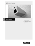
LTC 9405 Series
Wall/Ceiling Security Housings
Installation Instructions
Eng
Philips
Communication &
Security Systems
F
D
E
NL
I
IMPORTANT SAFEGUARDS
1.
Read Instructions - All the safety and operating instructions should be read
before the unit is operated.
2. Retain Instructions - The safety and operating instructions should be
retained for future reference.
3. Heed Warnings - All warnings on the unit and in the operating instructions
should be adhered to.
4. Follow Instructions - All operating and use instructions should be followed.
5. Cleaning - Unplug the unit from the outlet before cleaning. Do not use
liquid cleaners or aerosol cleaners. Use a damp cloth for cleaning.
6. Attachments - Do not use attachments not recommended by the product
manufacturer as they may cause hazards.
7. Water and Moisture - Do not use this unit near water - for example, near a
bath tub, wash bowl, kitchen sink, or laundry tub, in a wet basement, near
a swimming pool, in an unprotected outdoor installation, or any area which
is classified as a wet location.
8. Accessories - Do not place this unit on an unstable stand, tripod, bracket,
or mount. The unit may fall, causing serious injury to a person and serious
damage to the unit. Use only with a stand, tripod, bracket, or mount
recommended by the manufacturer, or sold with the product. Any
mounting of the unit should follow the manufacturer's instructions, and
should use a mounting accessory recommended by the manufacturer.
An appliance and cart combination should be moved with care.
Quick stops, excessive force, and uneven surfaces may cause the
appliance and cart combination to overturn.
9. Ventilation - Openings in the enclosure, if any, are provided for ventilation
and to ensure reliable operation of the unit and to protect it from
overheating. These openings must not be blocked or covered. This unit
should not be placed in a built-in installation unless proper ventilation is
provided or the manufacturer's instructions have been adhered to.
10. Power Sources - This unit should be operated only from the type of power
source indicated on the marking label. If you are not sure of the type of
power supply you plan to use, consult your appliance dealer or local power
company. For units intended to operate from battery power, or other
sources, refer to the operating instructions.
11. Grounding or Polarization - This unit may be equipped with a polarized
alternating-current line plug (a plug having one blade wider than the other).
This plug will fit into the power outlet only one way. This is a safety
feature. If you are unable to insert the plug fully into the outlet, try
reversing the plug. If the plug should still fail to fit, contact your electrician
to replace your obsolete outlet. Do not defeat the safety purpose of the
polarized plug.
Alternately, this unit may be equipped with a 3-wire grounding-type plug, a
plug having a third (grounding) pin. This plug will only fit into a
grounding-type power outlet. This is a safety feature. If you are unable to
insert the plug into the outlet, contact your electrician to replace your
obsolete outlet. Do not defeat the safety purpose of the grounding-type
plug.
12. Power-Cord Protection - Power-supply cords should be routed so that they
are not likely to be walked on or pinched by items placed upon or against
them, paying particular attention to cords and plugs, convenience
receptacles, and the point where they exit from the appliance.
1.2
13. Power Lines - An outdoor system should not be located in the vicinity of
overhead power lines or other electric light or power circuits, or where it
can fall into such power lines or circuits. When installing an outdoor
system, extreme care should be taken to keep from touching such power
lines or circuits as contact with them might be fatal. U.S.A. models only refer to the National Electrical Code Article 820 regarding installation of
CATV systems.
14. Overloading - Do not overload outlets and extension cords as this can result
in a risk of fire or electric shock.
15. Object and Liquid Entry - Never push objects of any kind into this unit
through openings as they may touch dangerous voltage points or short-out
parts that could result in a fire or electric shock. Never spill liquid of any
kind on the unit.
16. Servicing - Do not attempt to service this unit yourself as opening or
removing covers may expose you to dangerous voltage or other hazards.
Refer all servicing to qualified service personnel.
17. Damage Requiring Service - Unplug the unit from the outlet and refer
servicing to qualified service personnel under the following conditions:
a. When the power-supply cord or plug is damaged.
b. If liquid has been spilled, or objects have fallen into the unit.
c. If the unit has been exposed to rain or water.
d. If the unit does not operate normally by following the operating
instructions. Adjust only those controls that are covered by the
operating instructions, as an improper adjustment of other controls
may result in damage and will often require extensive work by a
qualified technician to restore the unit to its normal operation.
e. If the unit has been dropped or the cabinet has been damaged.
f. When the unit exhibits a distinct change in performance--this indicates
a need for service.
18. Replacement Parts - When replacement parts are required, be sure the
service technician has used replacement parts specified by the manufacturer
or have the same characteristics as the original part. Unauthorized
substitutions may result in fire, electric shock or other hazards.
19. Safety Check - Upon completion of any service or repairs to this unit, ask
the service technician to perform safety checks to determine that the unit is
in proper operating condition.
20. Coax Grounding - If an outside cable system is connected to the unit, be
sure the cable system is grounded. U.S.A. models only--Section 810 of the
National Electrical Code, ANSI/NFPA
No.70-1981, provides information with respect to proper grounding of the
mount and supporting structure, grounding of the coax to a discharge unit,
size of grounding conductors, location of discharge unit, connection to
grounding electrodes, and requirements for the grounding electrode.
21. Lightning - For added protection of this unit during a lightning storm, or
when it is left unattended and unused for long periods of time, unplug it
from the wall outlet and disconnect the cable system. This will prevent
damage to the unit due to lightning and power-line surges.
SAFETY PRECAUTIONS
CAUTION: TO REDUCE THE RISK OF ELECTRICAL
SHOCK, DO NOT OPEN COVERS. NO USER
SERVICEABLE PARTS INSIDE. REFER SERVICING TO
QUALIFIED SERVICE PERSONNEL.
This label may appear on the bottom of the unit due to space
limitations.
The lightning flash with an arrowhead symbol, within an
equilateral triangle, is intended to alert the user to the
presence of un-insulated "dangerous voltage" within the
product's enclosure that may be of sufficient magnitude to
constitute a risk of electric shock to persons.
The exclamation point within an equilateral triangle is
intended to alert the user to presence of important
operating and maintenance (servicing) instructions in the
literature accompanying the appliance.
WARNING
TO PREVENT FIRE OR SHOCK HAZARD, DO NOT
EXPOSE UNITS NOT SPECIFICALLY DESIGNED FOR
OUTDOOR USE TO RAIN OR MOISTURE.
1.3
1.4
CONTENTS
1
2
3
4
5
5.1
5.2
5.3
5.4
5.5
UNPACKING . . . . . . . . . . . . . . . . . . . . . . . . . .1.3
SERVICE . . . . . . . . . . . . . . . . . . . . . . . . . . . . . .1.3
CARE AND MAINTENANCE . . . . . . . . . . . . .1.3
DESCRIPTION . . . . . . . . . . . . . . . . . . . . . . . . .1.3
INSTALLATION . . . . . . . . . . . . . . . . . . . . . . . .1.4
Accessories . . . . . . . . . . . . . . . . . . . . . . . . . . . . .1.4
Disassembly . . . . . . . . . . . . . . . . . . . . . . . . . . . .1.4
Mounting the Unit . . . . . . . . . . . . . . . . . . . . . . .1.5
Camera/Lens Installation . . . . . . . . . . . . . . . . . . .1.6
Final Assembly . . . . . . . . . . . . . . . . . . . . . . . . . .1.7
1
UNPACKING
Unpack carefully. This is electro-mechanical equipment and
should be handled with care.
Check for the following items:
■
Model number of unit.
■
Hardware Kit.
(1) ¼-20 Button-Head Flange Screw
(1) Tamper-resistant Tool (basic models only)
(1) Alternate Camera Bracket
(1) Key (Locking models only)
If an item appears to have been damaged in shipment, replace it
properly in its carton and notify the shipper. If any items are
missing, notify your Philips Communication & Security
Systems Sales Representative or Customer Service.
The shipping carton is the safest container in which the unit
may be transported. Save it for possible future use.
2
For maximum protection and durability, the light weight cast
aluminum design of the LTC 9405 series housings provide the
strength equivalent 10 gage steel with the superior strength to
weight ratio of aluminum. The standard viewing window is
constructed of 9.5 mm (0.37 in.) clear polycarbonate treated
with a scratch-resistant coating. The removable cover provides
access to the camera and is secured with a single tamperresistant and captive screw. A special tool is provided for
turning the screw to open or close the cover. During servicing
or adjustment of the camera, the cover may be completely
removed or (if mounted on a ceiling) it may be left attached to
the top panel assembly using the "hinged slots" provided.
Attractively styled these housings are designed to be mounted
on the ceiling, on the wall horizontally or on the wall vertically.
Options include a key lock on the access panel and a clear
12.7 mm (0.5 in) viewing window.
5
This installation should be made by qualified service
personel and conform to the National Electrical Code
and applicable local codes.
Tools Required.
Allenwrench - 5/32-inch.
Wrench - 10 mm.
5.1 Disassembly
1. Remove the hardware kit from the shipping carton.
2. Models LTC 9405/00 and 9405/03 require the use of the
special tool to unscrew the tamper-resistant screw on the
front of the cover. See figure 1.
SERVICE
If the unit ever needs repair service, the customer should contact
the nearest Philips Communication & Security Systems Service
Center for return authorization and shipping instructions.
3
INSTALLATION
Models LTC 9405/01 and 9405/05 require the use of the
key to unscrew the lock on the front of the cover. See
figure 1.
CARE AND MAINTENANCE
There are no moving parts in this unit. Regularly scheduled
maintenance will help prolong the operation life of this unit.
Clean the viewing window as needed with a mild, non-abrasive
detergent in water and a soft cloth.
4
DESCRIPTION
The LTC 9405 series are wall or ceiling mounted security
housings designed for applications such as prisons, parking
garages and hospitals. These housings are ideal for any
application requiring secure CCTV monitoring.
LTC 9405 has an overall size of 279 mm x 165 mm x 140 mm
(11 in x 6.5 in x 5.5 in). The LTC 9405 series housings accept
camera-lens combinations up to 190 L x 68 W x 68 H mm (7.5
x 2.7 x 2.7 in).
Figure 1: Removing the cover
1.5
3. For all models, unscrew the screw or the lock until the front
of the cover is free from the top panel.
4. With the unit on a workbench or table, hold the cover
stationary. Remove the top panel by grasping it and pulling
it rearward, then upward for about 51 mm (2 in ), and
finally rearward again until the slots in the top panel have
cleared the studs in the cover.
5. Unscrew the flange nut and remove the camera mount
system from the top panel. See figure 2. Do not lose the
parts, they will be needed to mount the camera and
reassemble the unit.
2. Mark the anchor bolt locations on the mounting surface
using the holes in the top panel as a template. At least four
8-mm (5/16-in.) anchor bolts will be needed. Use of six
bolts is recommended.
3. Drill holes and install anchors as required by the type of
mounting surface.
4. Decide how the wiring will be routed to the unit. Two
knockouts for ½ inch conduit and one knockout for 3/4
inch conduit are provided. See figure 4.
Figure 4: Bolt Holes and Knockouts
5. Mount the top panel using the bolts and rout the wiring.
Figure 2: Removing the Mount System
5.2 Mounting the Unit
1. Position the top panel on the ceiling or wall, horizontally or
vertically, depending on the installation requirements. See
figure 3. A smooth flat surface is ideal for proper
installation. Note the minimum space requirements shown
in figure 3.
5.3 Camera/Lens Installation
1. If the installation requires that the camera be mounted
horizontally to a wall, remove the camera bracket from the
mounting system and install the alternate camera bracket
provided in the hardware kit. See figure 5.
Mounting Bracket
Screw
Screw
WARNING! - Do not use the hinge feature when the
unit is mounted on a wall. The cover may fall from
the top panel.
Camera Bracket
W9404408AE
Alternate
Camera Bracket
Figure 5: Alternate Camera Mount
2. Reattach the camera mounting system to the top panel using
the same hardware that was removed in step 5 of section
5.1. Use either of the two studs near the center of the
panel, depending on the camera / lens size. See figures 6
and 7.
Figure 3: Positioning the Top Panel
1.6
Figure 9: Camera and Mount System
Figure 6: Installing the Mount System
Figure 10: Camera Mounted with Alternate Bracket to a
Wall
Figure 7: Securing the Mount System with Alternate Bracket
5.4 Final Assembly
1. Mount the cover by aligning the two studs near the rear of
the cover with the openings of the z-shaped slots in the top
panel. Slide the cover to the rear, then upward and finally
to the rear again. Tighten tamper-resistant screw or lock
with key. See figure 11.
3. Secure the camera to the mount using the ¼-20 x ½ inch
button-head flange screw provided in the hardware kit. See
figures 8, 9 and 10.
Button Head
Flange Screw
Camera
Camera
Bracket
Camera
Button Head
Flange Screw
Alternate
Camera Bracket
W9404411AE
Figure 8: Camera Mounts
Figure 11: Installing the Cover
1.7
2. Inspect the alignment of the camera / lens in the unit. The
camera / lens should be placed as close to the viewing
window as possible. Remove the cover and make
adjustments as needed and then replace the cover.
3. Secure the cover by turning either the tamper-resistant screw
(using the drive tool supplied) or the keyed lock (using the
key supplied) clockwise until the cover is in tight contact
with the top panel.
Note: Save the drive tool or the key for future use.
4. For installations where the unit is mounted to the ceiling,
the top cover may be hinged open for servicing or adjusting
the camera / lens. Simply allow the two studs in the rear of
the cover to rest in the bottom of the z-slots in the top
panel.
Figure 12: Cover Hinged Open
WARNING! - Do not use the hinge feature when the
unit is mounted to a wall, the cover may fall from the
top panel.
1.8
SECURITE
ATTENTION
RISQUE DE CHOC ELECTRIQUE.
NE PAS OUVRIR.
DANGER: POUR ÉVITER TOUT RISQUE
D'ÉLECTROCUTION, NE PAS OUVRIR LE BOÎTIER. IL
N'Y A PAS DE PIÈCES REMPLAÇABLES À
L'INTÉRIEUR. POUR TOUTE RÉVISION, S'ADRESSER
À UN TECHNICIEN SPÉCIALISÉ.
En raison de limitation de place, cette étiquette peut être placée sur le
dessous de l'appareil.
L'éclair fléché dans un triangle équilatéral, avertit
l'utilisateur de la présence d'une "tension dangereuse" non
isolée à l'intérieur de l'appareil et d'une valeur suffisante
pour constituer un risque d'électrocution.
Le point d'exclamation contenu dans un triangle
équilatéral, avertit l'utilisateur de la présence, dans la
documentation qui accompagne l'appareil, de consignes
d'utilisation et de maintenance importantes.
ATTENTION
POUR ÉVITER LE RISQUE D'ÉLECTROCUTION OU
D'INCENDIE, NE PAS EXPOSER À LA PLUIE OU À
L'HUMIDITÉ UN APPAREIL NON CONÇU POUR
UNE UTILISATION EXTÉRIEURE.
2.1
2.2
TABLE DES MATIERES
1
2
3
4
5
5.1
5.2
5.3
5.4
DEBALLAGE . . . . . . . . . . . . . . . . . . . . . . . . . . .2.3
MAINTENANCE . . . . . . . . . . . . . . . . . . . . . . .2.3
ENTRETIEN ET MAINTENANCE . . . . . . . . .2.3
DESCRIPTION . . . . . . . . . . . . . . . . . . . . . . . . .2.3
INSTALLATION . . . . . . . . . . . . . . . . . . . . . . . .2.3
Démontage . . . . . . . . . . . . . . . . . . . . . . . . . . . . .2.3
Montage de l'unité . . . . . . . . . . . . . . . . . . . . . . .2.4
Installation du bloc caméra/objectif . . . . . . . . . . .2.5
Montage final . . . . . . . . . . . . . . . . . . . . . . . . . . .2.6
1
DEBALLAGE
Déballez soigneusement le contenu de l'emballage. Il contient
un équipement électromécanique qui doit être manipulé avec
précaution.
Vérifiez que vous disposez des éléments suivants :
■ Le numéro de référence de l'unité.
■ Un kit matériel.
(1) Vis à tête demi-ronde ¼-20
(1) Outil de protection contre les effractions (modèles
de base uniquement)
(1) Applique de fixation amovible de la caméra
(1) Clé (modèles avec verrouillage uniquement)
D'un encombrement réduit de 279 x 165 x 140 mm, les
LTC 9405 prennent en charge des blocs caméra/objectif aux
dimensions maximales suivantes : 190 (l) x 68 (d) x 68 (h) mm.
Grâce à leur conception ultra-légère en aluminium fondu, les
boîtiers LTC 9405 sont d'une résistance équivalente à un acier
de calibre 10 supérieure au ratio pondéré de l'aluminium et
bénéficient ainsi d'une protection et d'une solidité optimales. La
fenêtre de visualisation standard est conçue en polycarbonate
transparent de 9,5 mm et recouvert d'une couche anti-abrasive.
Le capot amovible, fixé au moyen d'une seule vis captive antieffraction, permet d'accéder à la caméra. Un outil spécial
(fourni) permet de l'ouvrir ou de le fermer en vissant ou
dévissant la vis. Lors de l'entretien ou du réglage de la caméra, il
est nécessaire de retirer complètement le capot. Dans le cadre
d'un montage sur plafond, cependant, il doit rester attaché au
panneau de montage supérieur au moyen des pitons de fixation.
Ces boîtiers attrayants sont conçus pour un montage mural, à
l'horizontale ou à la verticale, et sur plafond. Vous disposez en
option d'un verrou situé sur le panneau d'accès et d'une fenêtre
de visualisation transparente de 12,7 mm.
5
Seul un technicien qualifié est habilité à installer cette
unité, conformément aux normes électriques en vigueur
dans votre pays.
Si l'un des éléments semble avoir été endommagé lors du
transport, remettez-le dans son carton d'emballage et avertissez
le transporteur. Si l'un des éléments manque, contactez votre
représentant ou votre service clientèle Philips Communication
& Security Systems.
Aucun container n'est mieux adapté que le carton d'emballage
pour transporter l'unité. Nous vous conseillons donc de le
conserver. Vous pourriez en avoir besoin ultérieurement.
2
MAINTENANCE
Veuillez contacter le service de maintenance Philips
Communication & Security Systems le plus proche de votre
domicile pour assurer la maintenance ou la réparation de l'unité.
Vous obtiendrez une autorisation et toutes les informations
utiles sur le renvoi du produit.
3
Outils requis :
Clé à vis 5/32".
Clé à vis 10 mm.
5.1 Démontage
1. Retirez le kit matériel du carton d'emballage.
2. Pour retirer la vis anti-effraction située sur le panneau avant
du capot des modèles LTC 9405/00 et 9405/03, vous devez
utiliser l'outil spécial correspondant. Veuillez vous référer à
la figure 1.
Pour ouvrir le verrou situé sur le panneau avant du capot des
modèles LTC 9405/01 et 9405/05, vous devez utiliser la clé
correspondante. Veuillez vous référer à la figure 1.
ENTRETIEN ET MAINTENANCE
Cette unité n'intègre aucune pièce détachée. Une maintenance
régulière permet d'en prolonger la durée de vie. Nettoyez la
fenêtre au moyen d'un chiffon doux et d'un produit d'entretien
non abrasif dilué dans de l'eau.
4
INSTALLATION
DESCRIPTION
Les boîtiers de protection LTC 9405 pour montage mural ou
sur plafond ont été notamment conçus pour assurer la
surveillance des prisons, des parkings ou des garages et des
hôpitaux. Cependant, ils s'adaptent parfaitement à toutes les
applications nécessitant la mise en place d'un système de
vidéosurveillance en circuit fermé.
2.3
Panneau supérieur
AVERTISSEMENT - N'utilisez pas le système de
supports de fixation en forme de Z/pitons lorsque
vous montez l'unité sur un mur. En effet, le capot
pourrait se détacher du panneau supérieur.
Insérez les pitons
(situés de chaque côté)
dans les supports de
fixation en forme de Z
12-3/8 (14-3/8 min)
Si le système de supports de fixation en
forme de Z/pitons est utilisé
Panneau
avant du
boîtier
Orifices de fixation des boulons avec cheville (6)
Vis anti-effraction ou
verrou
-11/16
minimum
Capot
6-1/4
-11/16
minimum
Figure 1 : Retrait du capot
1-3/8 minimum
(2 in min. Si le
système de supports
de fixation en forme
de Z/pitons est
utilisé
3. Quel que soit le modèle, retirez la vis ou ouvrez le verrou
afin de dégager le panneau avant du capot du panneau
supérieur.
4. Placez l'unité sur un plan de travail ou une table et
immobilisez le capot. Retirez le panneau supérieur en le
tenant fermement et en le tirant vers l'arrière, en le soulevant
vers le haut sur environ 51 mm, puis en le tirant de nouveau
vers l'arrière jusqu'à ce que les supports de fixation soient
totalement dégagés des pitons correspondant situés sur le
capot.
5. Dévissez l'écrou, puis retirez le support de montage de la
caméra du panneau supérieur. Veuillez vous référer à la
figure 2. Ne perdez aucun éléments, vous en aurez besoin
pour remettre la caméra en place et remonter l'unité.
-1-3/8
minimum
Figure 3 : Installation du panneau supérieur
2. Marquez l'emplacement des boulons sur la surface de
montage au moyen des orifices situés sur le panneau
supérieur. Vous devez utiliser au moins quatre boulons de 8
mm. Nous vous recommandons cependant d'en utiliser six.
3. Percez les trous et installez les chevilles appropriées à la
surface de montage.
4. Déterminez l'acheminement des câbles jusqu'à l'unité. Cette
dernière intègre deux parois amovibles permettant le passage
d'un câble d'1/2" et une paroi amovible de 3/4". Veuillez
vous référer à la figure 4.
Orifices de fixation des boulons
avec cheville (6)
Panneau supérieur
Boulons
Parois
amovibles
Bague
d'insertion
Bague de réduction
Vis et rondelle
Rondelle
Panneau supérieur (vue de
dessous)
Ecrou
Support de
montage
Figure 2 : Retrait du système de montage
Figure 4 : Orifices pour boulons et parois amovibles
5. Fixez le panneau supérieur au moyen des boulons et
acheminez les câbles.
5.2 Montage de l'unité
1. Placez le panneau supérieur sur le plafond ou le mur, à
l'horizontale ou à la verticale, en fonction des exigences
requises par votre installation (figure 3). Pour que celle-ci
soit correcte, choisissez de préférence une surface plane et
lisse. Veuillez noter l'espace minimum requis en vous
référant à la figure 3.
2.4
Surface de montage
Veuillez vous référer à la figure 3 pour connaître
l'espace minimum requis
5.3 Installation du bloc caméra/objectif
1. Si dans le cadre d'une installation murale la caméra doit être
montée horizontalement, retirez le support de fixation de la
caméra du support de montage, puis installez l'applique de
fixation amovible de la caméra fournie dans le kit matériel.
Veuillez vous référer à la figure 5.
Boulons
Support de
fixation
Mounting Bracket
Vis
Screw
Screw
Vis
Bague d'insertion
Bague de réduction
Rondelle
Ecrou
Rondelle
Support de fixation de la
Camera Bracket
caméra
Alternate
Vis
W9404408AE
Applique de fixation amovible de la caméra
Applique
de fixation amovible
Camera Bracket
de la caméra
Figure 7 : Fixation du support de montage doté d'un support
de fixation amovible
Figure 5 : Applique de fixation amovible de la caméra
3. Fixez solidement la caméra au support au moyen de la vis à
tête demi-ronde 20¼ x ½" fournie dans le kit matériel.
Veuillez vous référer aux figures 8, 9 et 10.
2. Fixez le support de montage de la caméra au panneau
supérieur en utilisant les mêmes éléments que ceux que vous
avez ôtés lors de l'étape 5 de la section 5.1. Choisissez l'un
des deux boulons situés à peu près au centre du panneau en
fonction de la taille du bloc caméra/objectif. Veuillez vous
référer aux figures 6 et 7.
Vis
à tête
Button
Head
demi-ronde
Flange Screw
Caméra
Camera
Support de
Camera
fixation
de la
Bracket
caméra
Surface de montage
Veuillez vous référer à la figure 3 pour connaître
l'espace minimum requis
Camera
Caméra
Panneau supérieur
Applique de
Alternate
fixation amovible
Camera
Bracket
de la caméra
Vis à têteButton
demi-ronde
Head
Flange Screw
W9404411AE
Boulons
Figure 8 : Fixation de la caméra
Bague
d'insertion
Bague de réduction
Vis et rondelle
Rondelle
Ecrou
Support de
montage
Figure 6 : Installation du support de montage
Caméra
Support de
montage
Figure 9 : Caméra et support de fixation
2.5
Remarque : Conservez l'outil spécial ou la clé. Vous pourriez en
avoir besoin ultérieurement.
Caméra
4. Lorsque l'unité est montée au plafond, vous ne devez ouvrir
que la partie supérieure du capot pour entretenir et régler le
bloc caméra/objectif. Pour ce faire, faites glisser le capot
jusqu'à ce que les deux pitons se retrouvent dans le
renfoncement situé dans la partie inférieure du support en
forme de Z du panneau supérieur.
Applique de fixation amovible
de la caméra
Figure 10 : Montage mural d'une caméra fixée sur un support
amovible
5.4 Montage final
1. Remettez le capot en place en alignant les deux pitons situés
à l'arrière du capot avec les ouvertures des supports de
fixation en forme de Z situés sur le panneau supérieur. Faites
glisser le capot vers l'arrière, puis vers le haut et enfin vers
l'arrière. Fixez la vis anti-effraction ou ouvrez le verrou au
moyen de la clé. Veuillez vous référer à la figure 11.
AVERTISSEMENT - N'utilisez pas le système de
supports de fixation en forme de Z/pitons lorsque
vous montez l'unité sur un mur. En effet, le capot
pourrait se détacher du panneau supérieur.
Panneau supérieur
Panneau supérieur
Position du capot
partiellement ouvert
Insérez les
pitons (situés
de chaque
côté) dans les
supports de
fixation en
forme de Z
Vis anti-effraction ou
verrou
Figure 12 : Ouverture partielle du capot
Capot
Figure 11 : Installation du capot
2. Vérifiez que le bloc caméra/objectif est correctement
positionné à l'intérieur de l'unité. Il doit se trouver aussi près
que possible de la fenêtre de visualisation. Retirez le capot et
effectuez les réglages nécessaires, puis remettez le capot en
place.
3. Fixez le capot au moyen de la vis anti-effraction ou du
verrou (en utilisant respectivement l'outil spécial ou la clé
fourni) en tournant dans le sens des aiguilles d'une montre
jusqu'à ce que le capot soit fermement maintenu au niveau
du panneau supérieur.
2.6
SICHERHEITSVORKEHRUNGEN
VORSICHT
RISIKO EINES ELEKTRISCHEN
SCHLAGES NICHT ÖFFNEN!
VORSICHT: UM EINEN ELEKTRISCHEN SCHLAG ZU
VERMEIDEN, ABDECKUNG NICHT ENTFERNEN.
WARTUNGEN ALLER ART QUALIFIZIERTEM
PERSONAL ÜBERLASSEN.
Aus Platzgründen kann diese Warnung auf der Unterseite des Gerätes
angebracht sein.
Das Blitzsymbol im gleichseitigen Dreieck soll den
Benutzer auf nicht isolierte "Hochspannung" im Gehäuse
aufmerksam machen, die eventuell stark genug ist, um
einen elektrischen Schlag zu verursachen.
Das Ausrufezeichen im gleichseitigen Dreieck soll den
Benutzer auf wichtige Bedienungs- und
Wartungsanleitungen in der dem Gerät beigefügten
Literatur aufmerksam machen.
WARNUNG
UM FEUER ODER ELEKTRISCHE SCHLÄGE ZU
VERMEIDEN, SETZEN SIE DAS GERÄT NIEMALS
REGEN ODER FEUCHTIGKEIT AUS.
3.1
3.2
INHALT
1
2
3
4
5
5.1
5.2
5.3
5.4
AUSPACKEN . . . . . . . . . . . . . . . . . . . . . . . . . .3.3
SERVICE . . . . . . . . . . . . . . . . . . . . . . . . . . . . . .3.3
WARTUNG . . . . . . . . . . . . . . . . . . . . . . . . . . .3.3
BESCHREIBUNG . . . . . . . . . . . . . . . . . . . . . . .3.3
INSTALLATION . . . . . . . . . . . . . . . . . . . . . . . .3.3
Demontage . . . . . . . . . . . . . . . . . . . . . . . . . . . . .3.3
Montage der Einheit . . . . . . . . . . . . . . . . . . . . . .3.4
Installation der Kamera/Linse . . . . . . . . . . . . . . .3.5
Endmontage . . . . . . . . . . . . . . . . . . . . . . . . . . . .3.6
1
AUSPACKEN
Vorsichtig auspacken. Dies ist ein elektromechanisches Gerät
und sollte vorsichtig behandelt werden.
Überprüfen Sie die folgenden Dinge:
■ Modellnummer des Geräts.
■ Zubehörsatz.
(1) ¼-20 Halbrundkopf-Flanschschraube
(1) Gegen unbefugtes Verstellen gesichertes Werkzeug
(nur Grundmodelle)
(1) Wechsel-Kameraschiene
(1) Schlüssel (nur für Modelle mit Verriegelung)
Sollte einer der Posten beim Versand beschädigt worden sein,
verpacken Sie ihn entsprechend wieder in seinem Karton und
informieren Sie den Spediteur. Sollte ein Posten fehlen,
informieren Sie Ihren Philips Communication & Security
Systems Vertriebsverantwortlichen oder den Kundenservice.
LTC 9405 hat eine Größe von 279 mm x 165 mm x 140 mm).
Die Gehäuseserie LTC 9405 ermöglicht die Kombination von
Kameralinsen von bis zu to 190 x 68 x 68 mm (L x W x H).
Maximaler Schutz und maximale Lebensdauer des leichten
Gehäuses aus Aluminiumguß der Reihe LTC 9405 werden
gewährleistet durch ein sehr günstiges Festigkeits-GewichtsVerhältnis, wobei Werte erreicht werden, die der Festigkeit von
Stahl mit einem Reißmaß von 10 entsprechen. Das
standardmäßig vorhandene Sichtfenster besteht aus 9,5 mm
dickem durchsichtigem Polycarbonat und ist durch eine
spezielle Beschichtung vor Verkratzung geschützt. Die
abnehmbare Abdeckung, ermöglicht den Zugang zur Kamera
und ist durch eine gegen unbefugtes Verstellen gesicherte,
unverlierbare Schraube gesichert. Für das Drehen der Schraube
zum Öffnen oder Schließen der Abdeckung wird ein spezielles
Werkzeug mitgeliefert. Während der Kamerawartung bzw. einstellung kann die Abdeckung vollständig entfernt werden
oder (im Fall einer Deckenmontage) in der dafür vorgesehenen
Schwenkvorrichtung eingehängt bleiben, die sich an der
Befestigungsplatte befindet.
Die Gehäuse in attraktivem Design wurden zur
Deckenmontage, oder vertikalen bzw. horizontalen
Wandmontage konzipiert. Optional sind sie als zugangsseitig
abschließbare Ausführung und mit Sichtfenster von 12,7 mm
Stärke erhältlich.
5
Die Installation sollte von qualifiziertem ServicePersonal und gemäß anwendbarer lokaler Standards
vorgenommen werden.
Der Versandkarton ist der sicherste Behälter, in dem das Gerät
transportiert werden kann. Heben Sie ihn für den späteren
Gebrauch auf.
2
3
WARTUNG
In diesem Gerät gibt es keine beweglichen Teile. Regelmäßige
Wartung hilft, die Betriebsdauer des Gerätes zu verlängern.
Reinigen Sie das Sichtfenster, falls erforderlich, mit einem
milden, nicht-schleifenden und in Wasser gelösten Waschmittel
und einem sauberen Lappen.
4
Benötigte Werkzeuge.
Innensechskantschlüssel - 5/32-Zoll.
Schraubenschlüssel- 10 mm.
SERVICE
Sollte das Gerät repariert werden müssen, sollte der Kunde das
nächste Philips Communication & Security Systems Service
Center für die Retourgenehmigung und Versandanweisungen
kontaktieren.
INSTALLATION
5.1 Demontage
1. Nehmen Sie den Zubehörsatz aus dem Lieferkarton.
2. Bei den Modellen LTC 9405/00 und 9405/03 ist zum
Lösen der gegen unbefugtes Verstellen gesicherten Schraube
an der Vorderseite der Abdeckung das mitgelieferte
Spezialwerkzeug erforderlich. Siehe Abbildung 1.
Bei den Modellen LTC 9405/01 und 9405/05 kann die
Abdeckung nur mit dem Schlüssel geöffnet werden, der zum
an der Vorderseite befindlichen Schloß paßt. Siehe
Abbildung 1.
BESCHREIBUNG
Bei der Serie LTC 9405 handelt es sich um wand- oder
deckenmontierte Sicherheitsgehäuse für Anwendungsgebiete wie
z.B. Gefängnisse, Parkhäuser oder Krankenhäuser. Diese
Gehäuse sind ideal für alle Anwendungen, die eine sichere
Video-Überwachung verlangen.
3.3
Befestigungsplatte
WARNHINWEIS! - Verwenden Sie bei der
Wandmontage keinesfalls die Schwenkvorrichtung.
Die Abdeckung könnte ansonsten von der
Befestigungsplatte fallen.
lassen Sie die
Bolzen in die
Schlitze greifen
(an beiden
Seiten)
12-3/8 14-3/8 min.
Schwenkvorrichtung muß verwendet
werden
Vorderseite
des
Gehäuses
Löcher für die Ankerschrauben (6)
vor unbefugtem
Verstellen gesicherte
Schraube oder Schloß
mindestens
Abdeckung
mindestens
Abb. 1: Entfernen der Abdeckung
1 - 3/8 mindestens
(2 in. MIN
Schwenkvorrichtung muß
verwendet
werden
3. Gilt für alle Modelle: Lösen Sie die Schraube bzw.
Verriegelung, so daß sich die Vorderseite der Abdeckung
von der Befestigungsplatte löst.
4. Legen Sie das Gerät auf eine flache, standfeste Werkbank
oder einen Tisch. Entfernen Sie die Befestigungsplatte,
indem Sie sie nach hinten und dann 50 mm nach oben
ziehen, um sie dann wieder zurückzuschieben, bis die
Schlitze die Zapfen in der Abdeckung freigeben.
5. Lösen Sie die Bundmutter und entfernen Sie die
Montagevorrichtung für die Kamera von der
Befestigungsplatte. Siehe Abbildung 2. Bewahren Sie die
Teile gut auf, da sie später für die Installation der Kamera
und den erneuten Zusammenbau der Einheit benötigt
werden.
Befestigungsplatte
mindestens
Abbildung 3: Positionierung der Befestigungsplatte
2. Benutzen Sie die Löcher in der Befestigungsplatte als
Vorlage, um die Bohrungen für die Ankerschrauben an der
Wand bzw. Decke zu markieren. Es werden mindestens vier
8-mm Ankerschrauben benötigt. Empfohlen sind sechs
Schrauben.
3. Bohren Sie die Löcher und setzen Sie die Anker.
Berücksichtigen Sie dabei das Material, aus dem die
Montagefläche besteht.
4. Entscheiden Sie wie die Kabelzuführung verlaufen soll. Das
Gehäuse verfügt über zwei Aussparungen für Kabel mit
einem Durchmesser von 1,27 cm und eine Aussparung für
einen Kabel mit einem Durchmesser von 1,9 cm. Siehe
Abbildung 4.
Löcher für die Ankerschrauben
Bolzen
Distanzscheibe
Laufbuchse
Schraube und
Sicherungsscheibe
Sicherungsscheibe
Flanschschraube
Aussparungen
Montagevorrichtung
Befestigungsplatte (von
unten)
Figure 2: Entfernen der Montagevorrichtung
5.2 Montage der Einheit
1. Positionieren Sie die Befestigungsplatte an der Decke oder
Wand, (je nach Anforderung horizontal oder vertikal). Siehe
Abbildung 3. Die Installation erfolgt idealerweise auf
glatten, ebenen Oberflächen. Beachten Sie den in Abbildung
3 dargestellten Mindestplatzbedarf.
Abbildung 4: Bolzenlöcher und Aussparungen
5. Montieren Sie die Befestigungsplatte mit Hilfe der
Schrauben und legen Sie den Verlauf der Kabel fest.
3.4
Montageoberfläche. Siehe Abbildung 3 für den
Mindestplatzbedarf.
5.3 Installation der Kamera/Linse
1. Falls es erforderlich ist, die Kamera horizontal an der Wand
zu installieren, müssen die Kameraschienen der
Installationsvorrichtung entfernt und gegen die im
Zubehörset befindliche Kameraschiene ausgetauscht werden.
Siehe Abbildung 5.
Bolzen
Montageschiene
Mounting Bracket
Schraube
Screw
Screw
Schraube
Distanzring
Laufbuchse
Sicherungsscheibe
Bundmutter
Sicherungsscheibe
Kameraschiene
Camera Bracket
Alternate
Schraube
W9404408AE
Wechsel-Kameraschiene
Wechsel-Kameraschiene
Camera Bracket
Abbildung 7: Sichern der Installationsvorrichtung durch die
dem Zubehörset beiliegende Schiene
Abbildung 5: Von vertikaler Kamerainstallation auf
horizontale Installation wechseln
2. Befestigen Sie die Kamera-Installationsvorrichtung wieder an
der Befestigungsplatte. Benutzen Sie dafür dieselben
Komponenten, die Sie zuvor, wie in Schritt 5; Abschnitt 5.1
beschrieben, entfernt haben. In der Mitte der
Befestigungsplatte befinden sich zwei Aufnahmebolzen, von
denen Sie jeweils den Bolzen auswählen, der der Größe der
eingesetzten Kamera/Linse entspricht. Siehe Abbildungen 6
und 7.
3. Sichern Sie die Kamera mit der ¼-20 x ½ Zoll
Halbrundkopf-Flanschschraube, die dem Zubehörset
beiliegt. Siehe Abbildungen 8, 9 und 10.
HalbrundkopfButton Head
Flanschschraube
Flange Screw
Kamera
Camera
Camera
KameraSchiene
Bracket
Montageoberfläche. Siehe Abbildung 3 für den
Mindestplatzbedarf.
Camera
Kamera
HalbrundkopfButton Head
Flanschschraube
Flange Screw
Wechsel-KameraAlternate
Schiene
Camera Bracket
W9404411AE
Befestigungsplatte
Abbildung 8: Aufnahmevorrichtung der Kamera
Bolzen
Distanzring
Laufbuchse
Sicherungsscheibe
Schraube und
Sicherungsscheibe
Bundmutter
Montagevorrichtung
Kamera
Abbildung 6: Befestigen der Installationsvorrichtung
Aufnahmevorrichtung
Abbildung 9: Kamera und Aufnahmevorrichtung
3.5
4. Um Wartungs- oder Einstellarbeiten bei Kameras / Linsen
in deckenmontierten Gehäusen vorzunehmen, reicht es, die
Abdeckung lediglich abzuklappen. Die beiden
Aufnahmebolzen auf der Rückseite der Abdeckung müssen
dann in den z-förmigen Schlitzen der Befestigungsplatte
verharren.
Kamera
WARNHINWEIS! - Verwenden Sie bei der
Wandmontage keinesfalls die Schwenkvorrichtung.
Die Abdeckung könnte ansonsten von der
Befestigungsplatte fallen
Wechsel-Kameraschiene
Befestigungsplatte
Abbildung 10: Kamera mit Wechselschiene an der Wand
montiert
5.4 Endmontage
1. Bringen Sie die Abdeckung an. Dabei richten Sie die beiden
Bolzen an der Rückseite der Abdeckung so aus, daß sie in
die z-förmigen Schlitze in der Befestigungsplatte eingreifen
können. Schieben sie die Abdeckung zuerst nach hinten,
anschließend nach oben und dann wieder nach hinten.
Befestigen Sie die gegen unbefugtes Verstellen gesicherte
Schraube bzw. schließen Sie das Gehäuse mit dem
dazugehörigen Schlüssel ab. Siehe Abbildung 11.
abgeklappte Abdeckung
Befestigungsplatte
vor unbefugtem
Verstellen
gesicherte
Schraube oder
Schloß
Abbildung 12: Abgeklappte Abdeckung
Lassen Sie
die Bolzen
in die
Schlitze
greifen (an
beiden
Seiten)
Abdeckung
Abbildung 11: Installieren der Abdeckung
2. Überprüfen Sie die Ausrichtung der Kamera / Linse im
Gehäuse. Die Kamera / Linse sollte so nah wie möglich am
Sichtfenster plaziert sein. Falls erforderlich, entfernen Sie die
Abdeckung, um die Kameraausrichtung zu korrigieren.
Anschließend installieren sie die Abdeckung wieder.
3. Sichern sie die Abdeckung entweder durch Drehen der
gegen unbefugtes Verstellen gesicherten Schraube (benutzen
Sie dafür das mitgelieferte Spezialwerkzeug) oder den zum
Schloß passenden mitgelieferten Schlüssel. Drehen Sie dabei
im Uhrzeigersinn bis die Abdeckung dicht an der
Befestigungsplatte anliegt.
Beachten: Bewahren Sie das Werkzeug und den Schlüssel für
zukünftige Anwendungen gut auf.
3.6
PRECAUCIONES DE SEGURIDAD
PRECAUCION
RIESGO DE CHOQUE
ELECTRICO. ¡NO ABRIR!
PRECAUCION: PARA REDUCIR EL RIESGO DE
CHOQUE ELÉCTRICO, FAVOR NO ABRIR LA
CUBIERTA. ESTE EQUIPO NO CONSTA DE PIEZAS
O PARTES QUE REQUIEREN SERVICIO O
MANTENIMIENTO. PARA REPARACIONES FAVOR
REFERIRSE A UN TÉCNICO CALIFICADO.
Debido a limitaciones de espacio, esta etiqueta puede aparecer en la parte
inferior de la unidad.
El símbolo representado por un relámpago con punta de flecha
dentro de un triángulo equilátero, se muestra con el objetivo de
alertar al usuario que existen "voltages peligrosos" sin
aislamiento, dentro de la cubierta de la unidad. Dichos voltages
pueden ser de tal magnitud que constituyen un riesgo de
choque eléctrico a personas.
El símbolo de exclamación dentro de un triángulo equilátero, se
muestra con el objetivo de alertar al ususario de que
instrucciones de operación y mantenimiento importantes
acompañan al equipo.
PELIGRO
PARA EVITAR EL PELIGRO DE INCENDIO Ó
CHOQUE ELÉCTRICO, NO EXPONGA A LA LLUVIA
Ó HUMEDAD, EQUIPOS QUE NO HAN SIDO
DISEÑADOS PARA USO EXTERIOR.
4.1
4.2
CONTENIDO
4
1
2
3
4
5
5.1
5.2
5.3
5.4
DESEMBALAJE . . . . . . . . . . . . . . . . . . . . . . . . .4.3
SERVICIO . . . . . . . . . . . . . . . . . . . . . . . . . . . . .4.3
CUIDADO Y MANTENIMIENTO . . . . . . . . .4.3
DESCRIPCIÓN . . . . . . . . . . . . . . . . . . . . . . . . .4.3
INSTALACIÓN . . . . . . . . . . . . . . . . . . . . . . . . .4.3
Desmontaje . . . . . . . . . . . . . . . . . . . . . . . . . . . .4.3
Montaje de la unidad . . . . . . . . . . . . . . . . . . . . .4.4
Instalación de cámara/lente . . . . . . . . . . . . . . . . .4.5
Montaje final . . . . . . . . . . . . . . . . . . . . . . . . . . .4.6
La serie LTC 9405 son carcasas de seguridad montadas sobre pared
o techo, diseñadas para aplicaciones como prisiones, aparcamientos
y hospitales. Estas carcasas resultan idóneas para cualquier
aplicación que necesite una supervisión segura de TVCC.
1
DESEMBALAJE
Para obtener la máxima protección y duración, el diseño en
aluminio fundido ligero de las carcasas Serie LTC 9405
proporciona la resistencia equivalente a 10 medidas de acero
junto con la superior relación entre resistencia y peso del
aluminio. La ventana de visualización estándar está fabricada en
policarbonato transparente de 9,5 mm (0,37 pulg.), tratado con
revestimiento de protección resistente a las rayaduras. La tapa
desmontable proporciona acceso a la cámara y está asegurada
con un único tornillo blindado y cautivo. Se suministra una
herramienta especial para girar el tornillo para abrir o cerrar la
cubierta. Durante la reparación o ajuste de la cámara, se puede
retirar la tapa por completo o bien (si está montada en un
techo) se puede dejar fijada al conjunto del panel superior
utilizando las "ranuras con bisagras" suministradas.
Tenga precaución al desembalar. Se trata de un equipo
electromecánico y debe manipularse cuidadosamente.
Compruebe que la caja contiene lo siguiente:
■ Número de modelo de la unidad.
■ Juego de hardware.
(1) Tornillo biselado de cabeza cilíndrica de ¼-20
(1) Herramienta blindada (sólo en los modelos básicos)
(1) Soporte de cámara alternativo
(1) Llave (sólo en los modelos con bloqueo)
Si alguno de los elementos parece haber sufrido daños durante el
transporte, vuelva a embalarlo correctamente en su caja y
póngase en contacto con el transportista. Si falta algún
componente, notifíquelo a su distribuidor Philips
Comunicaciones y Seguridad o al Servicio de atención al cliente.
DESCRIPCIÓN
LTC 9405 tiene un tamaño total de 279 mm x 165 mm x
140 mm (11 pulg x 6,5 pulg x 5,5 pulg). Las carcasas Serie
LTC 9405 aceptan combinaciones de lentes de cámara de hasta
190 x 68 x 68 mm (7,5 x 2,7 x 2,7 pulg) (Longitud x anchura
x altura).
La caja de envío es el contenedor más seguro en el que se puede
transportar la unidad. Guárdela para posibles usos posteriores.
Con una presentación atractiva, estas carcasas están diseñadas
para montarlas en el techo, horizontalmente en la pared o
verticalmente en la pared. Las opciones incluyen un cerradura
en el panel de acceso y una ventana de visualización transparente
de 12,7 mm (0,5 pulg).
2
5
SERVICIO
En caso de que la unidad deba repararse, el cliente deberá
ponerse en contacto con el Centro de servicios Philips
Comunicaciones y Seguridad más cercano con el fin de obtener
la autorización para la devolución y las instrucciones de envío.
3
La instalación debe llevarse a cabo por personal de
servicio cualificado y cumplir el Código eléctrico
nacional (National Electrical Code) y los códigos locales
correspondientes.
CUIDADO Y MANTENIMIENTO
En esta unidad no existen piezas que puedan moverse. Un
mantenimiento programado con regularidad ayudará a
prolongar la vida útil de esta unidad. Limpie la ventana de
visualización siempre que lo necesite con un detergente suave y
no abrasivo mezclado con agua y un paño suave.
INSTALACIÓN
Herramientas necesarias.
Llave Allen - 5/32 de pulgada.
Llave inglesa - 10 mm.
5.1 Desmontaje
1. Extraiga el juego de hardware de la caja de envío.
2. En los modelos LTC 9405/00 y 9405/03 necesitará utilizar
la herramienta especial para desatornillar el tornillo blindado
de la parte frontal de la tapa. Véase la figura 1.
En los modelos LTC 9405/01 y 9405/05 necesitará utilizar
la llave para desatornillar la cerradura de la parte frontal de
la tapa. Véase la figura 1.
4.3
Panel superior
ADVERTENCIA: - No utilice la característica de
bisagras cuando monte la unidad en una pared. La
tapa puede caerse del panel superior.
Coloque los
pasadores en las
ranuras (ambos
lados)
12-3/8 (14-3/8 min.
si se utiliza la características de
bisagras)
Parte
frontal de
la carcasa
Orificios de los pernos de soporte (6)
Tornillo blindado o
cerradura con llave
Mínimo
Tapa
Mínimo
1-3/8 (2 pulg. mín. si
se utiliza la
características de
bisagras)
Figura 1: Extracción de la tapa
3. Para todos los modelos, desatornille el tornillo o la cerradura
hasta que la tapa se libere del panel superior.
4. Con la unidad sobre un banco de trabajo o una mesa,
mantenga la tapa fija. Extraiga el panel superior sujetándolo
y tirando hacia atrás y hacia arriba una distancia de 51 mm
(2 pulg) aproximadamente y, por último, hacia atrás de
nuevo hasta que las ranuras del panel superior se suelten de
los pasadores de la tapa.
5. Desatornille la tuerca biselada y extraiga el sistema de
montaje de la cámara del panel superior. Véase la figura 2.
No pierda las piezas, las necesitará para montar la cámara y
ensamblar de nuevo la unidad.
Mínimo
Figura 3: Colocación del panel superior
2. Marque las ubicaciones de los pernos de soporte en la
superficie de montaje utilizando como plantilla los orificios
del panel superior. Se necesitarán como mínimo cuatro
pernos de soporte de 8 mm (5/16 de pulgada). Se
recomienda utilizar seis pernos.
3. Taladre los orificios e instale los soportes en función del tipo
de superficie de montaje.
4. Decida cómo va a tender el cableado hacia la unidad. Se
suministran dos extractores para el conducto de ½ pulgada y
un extractor para el conducto de 3/4 de pulgada. Véase la
figura 4.
Panel superior
Orificios de los pernos de
soporte (6)
Pasadores
Separador
Tornillos y arandelas
Haz de rayos
Extractores
Arandela
Tuerca
biselada
Panel superior (vista inferior)
Sistema de
montaje
Figura 2: Extracción del sistema de montaje
5.2 Montaje de la unidad
1. Coloque el panel superior en el techo o la pared, en
horizontal o vertical, en función de los requisitos de
instalación. Véase la figura 3. Una superficie plana y lisa es
idónea para una instalación correcta. Tenga en cuenta los
requisitos mínimos de espacio mostrados en la figura 3.
Figura 4: Orificios de pernos y extractores
5. Monte el panel superior utilizando los pernos y tienda el
cableado.
4.4
Superficie de montaje
Véase la figura 3 para ver el espacio mínimo necesario
5.3 Instalación de cámara/lente
1. Si la instalación necesita que la cámara esté montada
horizontalmente en la pared, extraiga el soporte de la cámara
del sistema de montaje e instale el soporte de cámara
alternativo suministrado en el juego de hardware. Véase la
figura 5.
Pasadores
Soporte de
montaje
Mounting Bracket
Tornillo
Screw
Screw
Tornillo
Separador
Haz de rayos
Arandela
Tuerca biselada
Arandela
Soporte
cámara
Camera de
Bracket
Alternate
Tornillo
W9404408AE
Soporte de cámara alternativo
Soporte
cámara alternativo
Camera de
Bracket
Figura 5: Montaje de cámara alternativo
Figura 7: Fijación del sistema de montaje con el soporte
alternativo
2. Vuelva a fijar el sistema de montaje de la cámara al panel
superior utilizando el mismo hardware que se extrajo en el
paso 5 de la sección 5.1. Utilice una de los dos pasadores
situados cerca del centro del panel, en función del tamaño
de la cámara o la lente. Véanse las figuras 6 y 7.
Superficie de montaje
Véase la figura 3 para ver el espacio mínimo
necesario
3. Fije la cámara al montaje utilizando el tornillo biselado de
cabeza cilíndrica de ¼-20 x ½ pulgada suministrado en el
juego de hardware. Véanse las figuras 8, 9 y 10.
Tornillo
Buttonbiselado
Head
de cabeza
Flange cilíndrica
Screw
Cámara
Camera
Camera
Soporte
de
cámara
Bracket
Panel superior
Soporte de
cámara
Alternate
alternativo
Camera
Cámara
Pasadores
Tornillo biselado
Buttonde
Head
cabeza cilíndrica
Flange Screw
Separador
Camera Bracket
W9404411AE
Haz de rayos
Arandela
Tornillos y
arandelas
Tuerca biselada
Figura 8: Montajes de la cámara
Sistema de
montaje
Figura 6: Instalación del sistema de montaje
Cámara
Sistema de montaje
Figura 9: Cámara y sistema de montaje
4.5
ADVERTENCIA: - No utilice la característica de
bisagras cuando monte la unidad en una pared, la
tapa puede caerse del panel superior.
Cámara
Panel superior
Soporte de cámara alternativo
Figura 10: Cámara montada en una pared con el soporte
alternativo
Tapa en posición de abierto por las
bisagras
5.4 Montaje final
1. Monte la tapa alineando los dos pasadores cercanos a la
parte posterior de la tapa con las aberturas de las ranuras con
forma de z del panel superior. Deslice la tapa hacia atrás y
hacia arriba y, por último, hacia atrás de nuevo. Apriete el
tornillo blindado o bloquee con la llave. Véase la figura 11.
Panel superior
Figura 12: Tapa abierta por las bisagras
Tornillo blindado
o cerradura con
llave
Coloque
los
pasadores
en las
ranuras
(ambos
lados)
Tapa
Figura 11: Instalación de la tapa
2. Examine la alineación de la cámara / lente en la unidad. La
cámara / lente debe estar situada lo más cerca posible de la
ventana de visualización. Extraiga la tapa y realice los ajustes
necesarios y, a continuación, colóquela de nuevo.
3. Asegure la tapa girando hacia la derecha el tornillo blindado
(utilizando la herramienta de atornillar suministrada) o el
bloqueo de llave (utilizando la llave suministrada) hasta que
la tapa está en contacto estrecho con el panel superior.
Nota: Guarde la herramienta de atornillar o la llave para
utilizarlas posteriormente.
4. Para las instalaciones en las que la unidad se monta en el
techo, la tapa superior puede dejarse abierta por las bisagras
para reparar o ajustar la cámara o la lente. Deje
simplemente que los dos pasadores de la parte posterior de la
tapa descansen sobre la parte inferior de las ranuras en forma
de z del panel superior.
4.6
VEILIGHEIDSVOORZORGEN
VOORZICHTIG
RISICO VAN ELEKTRISCHE
SCHOK NIET OPENEN
LET OP: OPEN DE BEHUIZING NIET OM HET
RISICO OP EEN ELECTRISCHE SCHOK TE
VOORKOMEN. HET APPARAAT BEVAT GEEN
VERVANGBARE ONDERDELEN. LAAT
ONDERHOUD OVER AAN GEKWALIFICEERD
PERSONEEL.
Dit label kan wegens ruimtegebrek op de onderkant van het apparaat
zitten.
De bliksemflits in een gelijkzijdige driehoek is bedoeld om de
gebruiker te wijzen op de aanwezigheid van een niet
geïsoleerde hoge spanning binnen de behuizing van het
product. Deze spanning kan zo hoog zijn dat het risico van
een elektrische schok aan personen aanwezig is.
Het uitroepteken in een gelijkzijdige driehoek is bedoeld om
de gebruiker te waarschuwen voor de aanwezigheid van
belangrijke bedienings- of onderhoudsaanwijzingen in de bij
het apparaat behorende literatuur.
WAARSCHUWING: STEL DEZE UNIT NIET
BLOOT AAN REGEN OF VOCHT OM BRAND OF
GEVAAR OP EEN ELECTRISCHE SCHOK TE
VOORKOMEN.
5.1
5.2
INHOUD
1
2
3
4
5
5.1
5.2
5.3
5.4
UITPAKKEN . . . . . . . . . . . . . . . . . . . . . . . . . . .5.3
SERVICE . . . . . . . . . . . . . . . . . . . . . . . . . . . . . .5.3
ONDERHOUD EN REPARATIE . . . . . . . . . . .5.3
BESCHRIJVING . . . . . . . . . . . . . . . . . . . . . . . .5.3
INSTALLEREN . . . . . . . . . . . . . . . . . . . . . . . . .5.3
Demonteren . . . . . . . . . . . . . . . . . . . . . . . . . . . .5.3
Behuizing monteren . . . . . . . . . . . . . . . . . . . . . .5.4
Camera/lens monteren . . . . . . . . . . . . . . . . . . . .5.5
Montage afronden . . . . . . . . . . . . . . . . . . . . . . . .5.6
1
UITPAKKEN
Pak de onderdelen voorzichtig uit, want deze
elektromechanische apparatuur moet zorgvuldig worden
behandeld.
Controleer of de volgende onderdelen zijn geleverd:
■ Modelnummer van eenheid.
■ Hardwarekit.
(1) ¼-20 bolkopschroef
(1) speciaal hulpmiddel voor beveiligingsschroef (alleen
basismodellen)
(1) extra camerabeugel
(1) sleutel (alleen bij afsluitbare modellen)
Als een onderdeel transportschade vertoont, leg het dan
voorzichtig terug in de verpakking en geef de schade door aan
de expediteur. Ontbreken er onderdelen, neem dan contact op
met uw vertegenwoordiger van Philips CSS of met de
servicedienst.
De doos is de veiligste verpakking voor elke vorm van transport.
Bewaar hem daarom voor eventueel later gebruik.
2
De gegoten lichtgewicht behuizing is ongeveer even sterk als
staalplaat met een sterkte 10, maar aluminium biedt het
voordeel van de uitstekende verhouding tussen een laag gewicht
bij een hoge sterkte. Het standaardvenster bestaat uit
transparant polycarbonaat van 9,5 mm en is voorzien van een
krasbestendige coating. Het afneembare paneel biedt toegang tot
de camera en is afgesloten met één beveiligingsschroef. Bij de kit
wordt een speciaal gereedschap geleverd om de behuizing te
openen en te sluiten. Tijdens het onderhouden of instellen van
de camera kan het paneel volledig worden verwijderd of (bij
montage aan een plafond) kan men het vast aan het
bovenpaneel laten zitten in de aanwezige "scharnieren".
De aantrekkelijk vormgegeven behuizingen zijn ontworpen voor
montage aan het plafond of horizontaal of verticaal aan een
wand. Tot de opties behoren een slot om de behuizing af te
sluiten en een transparant cameravenster van 12,7 mm.
5
De installatie dient door gekwalificeerde technici en
overeenkomstig de lokale regelgeving te worden
uitgevoerd.
Benodigd gereedschap
moersleutel 5/32-inch.
moersleutel 10 mm.
5.1 Demonteren
1. Haal de eenheid uit de verpakking.
2. Voor de modellen LTC 9405/00 en 9405/03 is een speciaal
gereedschap nodig om de beveiligingsschroef in het
frontpaneel los te draaien. Zie afbeelding 1.
Bij de modellen LTC 9405/01 en 9405/05 is de speciale
sleutel nodig om het slot op het voorpaneel te openen. Zie
afbeelding 1.
SERVICE
Als ooit een reparatie noodzakelijk zou zijn, neem dan contact
op met het dichtstbijzijnde Philips CSS Service Centre voor
informatie over het verzenden ter reparatie.
3
ONDERHOUD EN REPARATIE
Dit apparaat bevat geen bewegende delen. Periodiek onderhoud
verlengt de levensduur van de eenheid. Reinig het cameravenster
zo vaak als nodig is met een zachte doek en een mild sopje
zonder bijtende reinigers.
4
INSTALLEREN
BESCHRIJVING
De LTC 9405-serie bestaat uit behuizingen voor montage aan
een wand of plafond, ontwikkeld voor toepassing in
bijvoorbeeld gevangenissen, parkeergarages en ziekenhuizen. De
behuizingen zijn de ideale oplossing voor omgevingen waar een
CCTV-camera beveiligd moeten worden gemonteerd.
De afmetingen van de behuizingen zijn 279 x 165 x 140 mm en
zij zijn geschikt voor combinaties van een camera en lens met
afmetingen tot 190 x 68 x 68 mm (l x b x h).
5.3
Bovenpaneel
WAARSCHUWING! Laat de behuizing nooit
opengeklapt hangen als u de eenheid aan een wand
ophangt, want dan kan het voorpaneel van het
bovenpaneel vallen.
Zorg dat aan
weerszijden de
steuntjes in de
uitsparingen
vallen.
12-3/8 (14-3/8 min.)
Gebruik de scharnierverbinding
Voorzijde
van
behuizing
Gaatjes voor bouten(6)
Beveiligings-schroef
of slot voor sleutel
minimaal
Behuizing
minimaal
Afbeelding 1: Behuizing openen
1-3/8 minimum
(2 in min.
Gebruik de
scharnierverbinding)
3. Draai het schroefje los of open het slot tot de voorzijde
loskomt van het bovenpaneel van de behuizing.
4. Leg de eenheid op een werkbank of tafel en houd de
behuizing in een stabiele positie. Verwijder het bovenpaneel
door die naar achteren te trekken, dan ongeveer 5 cm
omhoog en dan weer naar achteren tot de steuntjes in de
kap los zijn uit de uitsparingen in de bovenkant.
5. Draai de flensmoer los en neem de camerabeugel uit het
bovenpaneel. Zie afbeelding 2. Let op dat u geen onderdelen
verliest, want u hebt ze later nodig om de camera en de
behuizing weer te monteren.
minimaal
Afbeelding 3: Montage van bovenpaneel
2. Markeer de posities van de bevestigingsbouten op de
ondergrond waar u het paneel wilt monteren. Gebruik
daarbij de gaatjes in het paneel als mal. U moet minimaal
vier bouten van 8 mm gebruiken, maar we raden u aan er
zes te gebruiken.
3. Boor gaatjes en breng afhankelijk van de gekozen
ondergrond het juiste type bouten aan.
4. Bepaal hoe de bekabeling naar de behuizing zal gaan lopen.
De behuizing heeft twee doordrukgaatjes met een doorsnede
van 1,27 cm en een doordrukgaatje van 1,9 cm. Zie
afbeelding 4.
Bovenpaneel
Gaatjes voor bouten (6)
Steunen
Afstandsring
Draagbus
Schroefje en revet
Doordrukgaatjes
Revet
Flensmoer
Bevestigingssysteem
Bovenpaneel (onderaanzicht)
Afbeelding 2: Camerabevestiging losmaken
5.2 Behuizing monteren
1. Monteer het bovenpaneel horizontaal of verticaal aan een
wand of plafond in de door u gewenste positie. Zie
afbeelding 3. Het beste is een egaal oppervlak. Let op de
minimaal vereiste ruimte, zoals in afbeelding 3 is
aangegeven.
Afbeelding 4: Boutgaatjes en doordrukgaatjes
5.
5.4
Monteer het bovenpaneel en leg de bedrading.
Montageoppervlak. Zie afb .3 voor minimaal
vereiste ruimte.
5.3 Camera/lens monteren
1. Als u de camera horizontaal aan een wand wilt monteren,
maak de camera dan los van de montagebeugel en monteer
de andere camerabeugel die als onderdeel van de kit is
geleverd. Zie afbeelding 5.
Steunen
Bevestigingsbeugel
Mounting Bracket
Schroef
Screw
Screw
Schroef
Afstandsring
Draagbus
Revet
Flensmoer
Revet
Camerabeugel
Camera Bracket
Alternate
Schroef
W9404408AE
Alternatieve camerabeugel
Alternatieve
camerabeugel
Camera Bracket
Afbeelding 5: Andere camerabeugel monteren
Afbeelding 7: Bevestigingssysteem met andere beugel
monteren
2. Monteer de camerabeugel weer aan het bovenpaneel met
dezelfde montageonderdelen die u in stap 5 onder 5.1 hebt
verwijderd. Gebruik een van de twee steunen bij het midden
van het paneel, afhankelijk van de afmetingen van de camera
en de lens. Zie de afbeeldingen 6 en 7.
3. Zet de camera vast aan de beugel met behulp van de ¼-20 x
½ inch bolkopflensschroef die bij de eenheid is geleverd. Zie
de afbeeldingen 8, 9 en 10.
BolkopflensButton Head
schroef
Flange Screw
Camera
Camera
CameraCamera
beugel
Bracket
Montageoppervlak. Zie afb. 3 voor minimaal
vereiste ruimte.
Camera
Camera
Bovenpaneel
Alternatieve
Alternate
camerabeugel
Camera Bracket
Bolkopflensschroef
Button Head
Flange Screw
W9404411AE
Afbeelding 8: Camerabevestigingen
Steunen
Afstandsring
Draagbus
Schroef met revet
Revet
Flensmoer
Bevestigingssysteem
Afbeelding 6: Bevestigingssysteem monteren
Camera
Bevestigingssysteem
Afbeelding 9: Camera en bevestigingssysteem
5.5
4. Als de camera aan een plafond wordt opgehangen, dan kan
het bovenpaneel worden geopend om onderhoud te plegen
of de positie van de lens en de camera aan te passen. Zorg
dat de twee steunen bij de achterzijde van de kap in de Zvormige uitsparingen in het bovenpaneel blijven rusten.
Camera
WAARSCHUWING! Laat de behuizing nooit
opengeklapt hangen als u de eenheid aan een wand
ophangt, want dan kan het voorpaneel van het
bovenpaneel vallen.
Alternatieve camerabeugel
Bovenpaneel
Afbeelding 10: Camera met alternatieve beugel bevestigd aan
een wand
5.4 Montage afronden
1. Monteer de behuizing door de twee steunen bij de
achterzijde van de kap uit te lijnen op de openingen van de
Z-vormige uitsparingen in het bovenpaneel. Schuif het
paneel naar achter, dan iets naar boven en dan weer naar
achter. Draai de beveiligingsschroef vast of draai het slot met
de sleutel dicht. Zie afbeelding 11.
Opengeklapte behuizing
Bovenpaneel
Afbeelding 12: Opengedraaide behuizing
Beveiligingsschroef
of slot met sleutel
Zorg dat
aan
weerszijden
de steuntjes
in de
uitsparingen
vallen.
Behuizing
Afbeelding 11: Behuizing monteren
2. Controleer of de camera en de lens op de juiste positie in de
behuizing zijn aangebracht. De lens moet zo dicht mogelijk
bij het venster hangen. Als dit niet optimaal is, maak dan de
behuizing open, breng de gewenste wijzigingen aan en maak
de behuizing weer dicht.
3. Sluit de behuizing af door de beveiligingsschroef vast te
draaien (met het bijgeleverde hulpmiddel) of draai het slot
dicht (met de bijgeleverde sleutel). U draait de schroef of de
sleutel rechtsom tot de behuizing tegen het bovenpaneel
aansluit.
Opmerking: Bewaar het speciale hulpmiddel of de sleutel op
een veilige plaats.
5.6
NORME CAUTELATIVE DI SICUREZZA
AVVERTENZA
RISCHIO DI FOLGORAZIONE
NON APRIRE!
ATTENZIONE: PER RIDURRE IL RISCHIO DI
SCOSSE ELETTRICHE, NON APRIRE I COPERCHI.
ALL’INTERNO NON VI SONO COMPONENTI SU
CUI L’UTENTE DEVE ESEGUIRE INTERVENTI DI
MANUTENZIONE. AFFIDARE LA
MANUTENZIONE A PERSONALE QUALIFICATO.
A causa di limitazioni di spazio questa etichetta può essere collocata sul
fondo dell’apparecchio.
Il simbolo del fulmine con la freccia, all’interno di un
triangolo equilatero, intende avvisare l’utente della presenza
di una “tensione pericolosa” non isolata all’interno del
contenitore, che può essere abbastanza elevata da costituire
un rischio di scossa elettrica per le persone.
Il punto esclamativo all’interno di un triangolo equilatero
intende avvisare l’utente della presenza, negli stampati che
accompagnano l’apparecchio, di importanti istruzioni per
l’uso e la manutenzione.
AVVERTENZA: PER EVITARE RISCHI D’INCENDIO
O DI SCOSSE ELETTRICHE, NON ESPORRE ALLA
PIOGGIA O ALL’UMIDITÀ APPARECCHI NON
SPECIFICATAMENTE PROGETTATI PER USO
ALL’ESTERNO.
6.1
6.2
CONTENUTI
1
2
3
4
5
5.1
5.2
5.3
5.4
DISIMBALLAGGIO . . . . . . . . . . . . . . . . . . . . .6.3
ASSISTENZA . . . . . . . . . . . . . . . . . . . . . . . . . .6.3
CURA E MANUTENZIONE . . . . . . . . . . . . . .6.3
DESCRIZIONE . . . . . . . . . . . . . . . . . . . . . . . . .6.3
INSTALLAZIONE . . . . . . . . . . . . . . . . . . . . . . .6.3
Disimballaggio . . . . . . . . . . . . . . . . . . . . . . . . . .6.3
Montaggio dell'unità . . . . . . . . . . . . . . . . . . . . . .6.4
Installazione di telecamera/ottica . . . . . . . . . . . . .6.5
Montaggio finale . . . . . . . . . . . . . . . . . . . . . . . . .6.6
1
DISIMBALLAGGIO
Disimballare con cautela. Si tratta di attrezzature elettromeccaniche da maneggiare con cura.
Controllare i seguenti componenti:
■ Numero di modello dell'unità.
■ Kit ferramenta.
(1) Vite per flangia da ¼-20
(1) Utensile per vite antiscasso (solo modelli base)
(1) Staffa telecamera alternativa
(1) Chiave (solo modelli con serratura)
combinazioni telecamera-ottica con dimensioni fino a 190 P x
68 L x 68 A mm.
Per la massima protezione e resistenza, la leggera struttura in
alluminio stampato degli alloggiamenti serie LTC 9405
garantisce una resistenza pari all'acciaio 10 con una resistenza
superiore data dal rapporto di peso dell'alluminio. La finestra
standard è realizzata in policarbonato neutro da 9,5 mm trattato
con un rivestimento anti-graffio. Il coperchio rimovibile
consente l'accesso alla telecamera ed è fissato con una vite
prigioniero antiscasso. Viene fornito uno speciale strumento per
stringere o svitare la vite che chiude il coperchio. Per
semplificare la regolazione o la manutenzione della telecamera, è
possibile rimuovere completamente il coperchio, oppure (per
installazioni a soffitto) lasciarlo collegato al pannello superiore
tramite i "cardini".
Eleganti nel design, questi alloggiamenti sono progettati per il
montaggio a soffitto, od a parete in posizione orizzontale o
verticale. Tra le opzioni una serratura a chiave sul pannello di
accesso ed una finestra neutra da 12,7 mm.
5
INSTALLAZIONE
L'installazione deve essere effettuata esclusivamente da
personale qualificato nel rispetto del codice elettrico
nazionale e delle normative locali vigenti.
Se un componente ha subito dei danni durante la spedizione,
inserirlo nella confezione e notificare l'accaduto allo
spedizioniere. Se un componente risulta mancante, notificarne
la mancata consegna al rappresentate commerciale o
all'assistenza clienti di Philips Communication & Security
Systems.
Strumenti necessari.
Chiave Allen - 5/32 pollici.
Chiave - 10 mm.
L'imballo è il contenitore più sicuro ed idoneo per il trasporto
dell'unità. Conservarlo per impieghi futuri.
5.1 Disimballaggio
1. Estrarre il kit ferramenta dall'imballo.
2
2. I modelli LTC 9405/00 e 9405/03 richiedono l'impiego di
uno strumento speciale per svitare la vite antiscasso situata
sulla parte frontale del coperchio. Vedi figura 1.
ASSISTENZA
Se l'unità dovesse richiedere un intervento d'assistenza, il cliente
è pregato di contattare il Centro assistenza Philips
Communication & Security Systems più vicino per ottenere il
numero di autorizzazione al rientro e le istruzioni per la
spedizione.
3
I modelli LTC 9405/01 e 9405/05 richiedono l'impiego
della chiave per aprire la serratura situata sulla parte frontale
del coperchio. Vedi figura 1.
CURA E MANUTENZIONE
Nell'unità non vi sono parti in movimento. Un programma di
manutenzione periodico favorisce il prolungamento della vita
utile di quest'unità. Pulire la finestra quando necessario con un
detergente delicato, non abrasivo diluito con acqua ed un panno
morbido.
4
DESCRIZIONE
La serie LTC 9405 è costituita da alloggiamenti di sicurezza
installabili a parete o su soffitti, progettati per applicazioni quali
istituti di pena, parcheggi e garage ed ospedali. Questi
alloggiamenti sono ideali per qualsiasi applicazione che prevede
attività di monitoraggio CCTV di sicurezza.
L'LTC 9405 ha dimensioni globali di 279 mm x 165 mm x
140 mm. Questi alloggiamenti sono in grado di alloggiare
6.3
Pannello superiore
AVVERTENZA! - Non utilizzare i cardini quando
l'unità è montata a parete. Il coperchio potrebbe
scivolare fuori dal pannello superiore.
Individvare le viti
prigioniere nelle
scanalature
(entrambi i lati)
12-3/8 (14-3/8 min.
se la caratteristica della cerniera deve
essere usata
Fori bulloni di ancoraggio (6)
Parte
anteriore de
alloggiamento
Vite antiscasso o
serratura a chiave
minimo
Coperchio
minimo
1-3/8 min. (2in. min.
se la caratteristica
della cerniera deve
essere usata
Figura 1: Rimozione del coperchio
3. Per tutti i modelli, svitare la vite od aprire la serratura per
sganciare il coperchio dal pannello frontale.
minimo
Figura 3: Collocazione del pannelli superiore
4. Collocando l'unità su un piano di lavoro o su un tavolo,
tenere fermo il coperchio. Rimuovere il pannello superiore
tirandolo indietro, poi sollevandolo di circa 51 mm, ed
infine portarlo nuovamente indietro finché i perni del
coperchio non si liberano dalle fessure sul pannello
superiore.
5. Svitare il dado della flangia e rimuovere il sistema di
fissaggio della telecamera dal pannello superiore. Vedi figura
2. Non perdere i componenti, perché saranno necessari per
montare la telecamera e riassemblare l'unità.
2. Marcare le posizioni del bullone di ancoraggio sulla
superficie di montaggio utilizzando come dima i fori
presenti sul pannello superiore. Sono necessari almeno
quattro bullono da 8-mm (5/16 pollici). Si suggerisce
l'utilizzo di sei bulloni.
3. Forare ed installare gli ancoraggi necessari dal tipo di
superficie di montaggio.
4. Stabilire la disposizione del cablaggio. Sono disponibili due
tasselli asportabili per condotti da 1/2 di pollice ed uno per
un condotto da 3/4 di pollice. Vedi figura 4.
Pannello superiore
Fori bulloni di ancoraggio (6)
Perni
Distanziatore
Boccola
Vite e rondella
Tasselli
asportabili
Rondella
Dado flangia
Sistema di
fissaggio
Pannello superiore (vista
inferiore)
Figura 2: Rimozione del sistema di fissaggio
5.2 Montaggio dell'unità
1. Collocare il pannello superiore sul soffitto o sulla parete, in
posizione orizzontale o verticale, a seconda delle specifiche
esigenze. Vedi figura 3. Una superficie piana e regolare è
ideale per una corretta installazione. Tenere presenti i
requisiti di spazio minimi necessari evidenziati un figura 3.
Figura 4: Fori per bulloni e tasselli asportabili
5. Montare il pannello superiore utilizzando i bulloni e
disporre il cablaggio.
6.4
5.3 Installazione di telecamera/ottica
1. Se l'installazione richiede che la telecamera venga montata in
orizzontale sulla parete, rimuovere la staffa porta telecamera
dal sistema di fissaggio ed installare la staffa alternativa
fornita con il kit ferramenta. Vedi figura 5.
Superficie di montaggio Vedi figura 3 per i requisiti
di spazio minimi
Perni
Staffa di
montaggio
Mounting Bracket
Vite
Screw
Screw
Vite
Distanziatore
Boccola
Rondella
Dado flangia
Rondella
Staffa
telecamera
Camera
Bracket
Alternate
Vite
W9404408AE
Staffa telecamera alternativa
Staffa
telecamera
Camera
Bracket alternativa
Figura 7: Montaggio del sistema di fissaggio con staffa
alternativa
Figura 5: Montaggio staffa telecamera alternativa
3. Fissare la telecamera al supporto con la vite per flangia da ¼20 x ½ pollici fornita con il kit ferramenta. Vedi figure 8, 9
e 10.
2. Ricollegare il sistema di fissaggio telecamera al pannello
superiore tramite la stessa ferramenta rimossa al punto 5
della sezione 5.1. Utilizzare uno dei due perni in prossimità
del centro del pannello, a seconda delle dimensioni del
gruppo telecamera / ottica. Vedi figure 6 e 7.
Vite
per Head
flangia
Button
Flange Screw
Telecamera
Camera
StaffaCamera
telecamera
Bracket
Superficie di montaggio Vedi figura 3 per i requisiti
di spazio minimi
Camera
Telecamera
Staffa
telecamera
Alternate
alternativa
Camera Bracket
Vite per flangia
Button Head
Flange Screw
W9404411AE
Pannello superiore
Figura 8: Montaggi telecamera
Perni
Distanziatore
Boccola
Rondella
Vite e rondella
Dado flangia
Sistema di
fissaggio
Telecamera
Figura 6: Installazione del sistema di fissaggio
Sistema di fissaggio
Figura 9: Telecamera e sistema di fissaggio
6.5
4. Per installazioni in cui l'unità viene montata a soffitto, il
coperchio superiore può essere fissato in posizione aperta per
le operazioni di regolazione o manutenzione del gruppo
telecamera / ottica. E' sufficiente fare in modo che i due
perni posti sul retro del coperchio si inseriscano nella parte
inferiore delle fessure a forma di z del pannello superiore.
Telecamera
AVVERTENZA! - Non utilizzare i cardini quando
l'unità è montata a parete, in quanto il coperchio
potrebbe sganciarsi dal pannello superiore.
Staffa telecamera alternativa
Pannello superiore
Figura 10: Telecamera installata a parete con staffa alternativa
5.4 Montaggio finale
1.
Montare il coperchio allineando i due perni in
prossimità del retro del coperchio con le aperture delle fessure a
forma di z del pannello superiore. Far scorrere il coperchio perso
il retro dell'unità, poi verso l'alto ed infine nuovamente verso il
retro. Stringere la vite antiscasso o chiudere la serratura. Vedi
figura 11.
Coperchio agganciato
Pannello superiore
Figura 12: Coperchio in posizione aperta
Vite antiscasso o
serratura a chiave
colloc are i
perni nelle
fessure
(entra mbi i
lati)
Coperchio
Figura 11: Installazione del coperchio
2. Verificare l'allineamento del gruppo telecamera / ottica
all'interno dell'unità. Il gruppo telecamera / ottica deve
essere collocato il più vicino possibile alla finestra.
Rimuovere il coperchio e procedere con le regolazioni, poi
reinstallare il coperchio.
3. Fissare il coperchio avvitando la vite antiscasso (con il
strumento in dotazione) o ruotando la serratura (con la
chiave in dotazione) in senso orario fino a serrare il
coperchio contro il pannello superiore.
Nota: Conservare il strumento per la vite antiscasso o la
schiave per esigenze future.
6.6
6.7
3935 890 21181 99-40
© 1999 by Philips Electronics N.V.
© 1999 by Philips Communication & Security Systems Inc.
All Rights Reserved. Philips® is a registered trademark of Philips Electronics N. A. Corp.
Data subject to change without notice