1
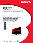
50" DLP™ HDTV
Quick-Use and Setup Guide
IMPORTANT
This owner's manual is used with several different television models. Not all features (and
drawings) discussed in this manual will necessarily match those found with your television set.
This is normal and does not require that you contact your dealer or request service.
MAGNAVOX representatives are ready to help you with any questions about your new product.
Call us at 1-800-705-2000 or visit us on the web at WWW.MAGNAVOX.COM.
WARNING: TO PREVENT FIRE OR SHOCK HAZARD DO NOT
EXPOSE THIS UNIT TO RAIN OR EXCESSIVE MOISTURE.
Hooking up the TV
Your TV is designed to accept and display a wide range of video programs and signal sources,including VCRs, DVD players, high definition (HD) TV devices,
video game consoles, and regular TV broadcasts. These are a sample of devices that can be connected to the TV's front and rear panel connectors.
Front panel
Back panel
Antenna in
S-Video
Headphones
Camera
Video
L
R
Game console
Connection Basics
Best
HDMI
High-definition
Multimedia Interface
provides an
uncompressed,
all-digital audio/video
connection. HDMI
provides the ultimate
connection.
Better
Component Video
Provides superior
picture quality by
separating the green,
blue, and red luminance
signals. Typically used
with red/white audio
cables.
Good
S-Video
Supplies a better picture
than RF and Composite
connections. Used with
red/white audio cables.
Basic
Composite Audio/Video
Separate video (yellow)
and audio (red/white)
cables that provide a
basic connection from
the cable box or other
devices.
Note: The color of audio
inputs may differ, e.g.
red/white or red/black.
Basic
RF
Provides a basic
connection for
antenna or cable.
Provides both
audio and video.
VCR
Hooking up cable TV/antenna
PVR
Set-top box DVD
Amplifier
PC Antenna in HDMI device
Connecting a set-top box
Connect a set-top box (cable or satellite) to the TV
as follows:
1. Connect the video output of the
set-top box to the component
video (YPbPr) connectors of the
AV3 input using RCA cables.
To view High Definition local broadcasts, connect
your outdoor or indoor antenna to the Antenna In
input on the rear panel. To view Analog Cable,
connect your Cable TV to the Antenna In input on
the rear panel.
Refer to the illustration for the
location of the Antenna In input.
Note: You can also connect the
video output to the V connector.
Antenna in
2. Connect the audio output (L/R) of
the set-top box to the audio jacks
(L/R) using RCA cables.
Connecting a VCR
Connecting a DVD
Connecting a camera
Follow these instructions to connect a VCR
(Video Cassette Recorder).
Use the following procedure to connect a DVD player To connect a camera to the TV, you can use the
AV connectors located on the front connector
to the TV.
panel (AV7). Alternatively, you can also use the
1. Connect the video output of the VCR to the
AV connectors located on the rear
1. Connect the video output of the DVD player to
panel.
V connector of the AV1 input using an RCA
the V connector of the AV4 input using an RCA
cable. Alternatively, you can also connect it to
cable. Alternatively, you can also connect it to the 1. Connect the video output of the camera to
the S-video connector of the AV1 input using an
component (YPbPr) connectors.
the S-video connector on the front panel using
S-video cable.
2. Connect the audio output (L/R) of the DVD player
an S-video cable. Alternatively, you can also
connect it to the V connector using an RCA
to the audio jacks (L/R) using RCA cables
2. Connect the audio output (L/R) of the VCR to
cable.
2. Connect the audio output (L/R) of the camera
the audio jacks (L/R) of the AV1 input using RCA
to the audio jacks (L/R) using RCA cables.
cables.
S-Video
S-Video
Video
L
R
Video
L
R
Operating the TV
Remote control buttons
Inserting remote control batteries
IR filter
Info
Power
INFO
Channel number
keys
Dash key
MTS
Recall
Channel up/down
Closed Captions
-
Volume up/down
Mute
Source shortcut
keys
OK
Arrow keys
OSD menu
MENU
Smart Picture
Smart Sound
Source selection
Picture size
Electronic
program guide
Sleep
Freeze picture
SOUND
PIP SIZE
PIP/PBP
PIP/PBP buttons
Using the TV buttons
1. The battery cover is on the
back of the remote control.
Slide the battery cover in the
direction of the arrow to
remove it.
MAGNAVOX
2. Insert the two AAA batteries
provided in the package, with
the polarity of the batteries
matching the image in the
battery compartment.
3
1 2
3. Slide the battery cover in the
direction of the arrow until it
clicks and is secure.
Turning on the TV
4
5
1. Press to view or exit from the OSD menu.
2. Press to skip to the previous or next
channel.
3. Press to increase or decrease the volume.
4. Press to select an input source or confirm
selection of a menu item.
5. Press to turn power on or off.
Turning off the TV
To switch on the TV:
1. Connect the power cord to the TV as
illustrated.
2. Plug the cord into a wall outlet.
3. Switch on the main power switch
located at the left side of the display.
4. Press the power button on the front
panel or remote control to turn on
the TV. The TV will turn on after
warming up for approximately
30 seconds.
Power
switch
Note:
If the remote control and control panel do not
work, ensure that the power switch on the rear
of the TV is set to ON.
To switch the TV off:
Press the power button on the front panel or
remote control to turn off the TV. The screen turns
blank immediately but it will take approximately
one minute to cool down and then shut down the
whole system.
Except in case of emergency, it is not recommended
to use the main power switch to switch off the
system. The lamp life may be severely reduced if the
system is not allowed to cool down properly by abruptly
shutting down the system using the main power switch.
Power switch
Selecting the source
After switching on the TV, select the appropriate input source using the front panel buttons or the remote control as follows:
• Press ATV, DVI/HDMI, YPbPr, DTV, AV, SV, or VGA on the remote control to switch to the respective input.
• Press the ENTER/SOURCE button on the front panel of the TV repeatedly to switch through all the input sources.
• Press SOURCE on the remote control to select the source from the on-screen menu. A list of input sources is displayed on
the screen. Select the appropriate input using the cursor keys and press OK on the remote control to display the input signal.
Input Select
EXIT
ATSC
Analog TV
AV1
AV2
AV3
AV4
HDMI
VGA
Front
Using the OSD menu
The On-Screen Display (OSD) menus enable you to customize the TV’s audio, video, and other settings according to your preferences.
Press the MENU button on the front panel or the remote control to view the OSD menu.
- Use the cursor keys to navigate through the menu items.
- Press OK to select an option.
- Press the MENU button again to exit from the menu.
Setting the language
Setting the tuner mode
The setup menu provides various options to
customize the TV’s settings. Select the Language
option from the menu and use the cursor keys to
select the desired OSD language.
Main Menu
The channel setup menu helps you to configure and
set up channels. Select the Tuner Mode option and
use the cursor keys to select antenna or cable input
for the tuner.
Main Menu
Picture
OSD Hold Time
5s
Sound
Language
English
Size
Sleep Timer
Off
PIP/PBP
Closed Caption
Press Right to
Parental Control
Time Zone
Atlantic
Eastern
Central
Pacific
Alaska
Hawaii
Channel Setup
Setup
Daylight Saving
Exit
Back
Off
Copyright 2005. All rights reserved.
10s
15s
Español
15m
On
20s
30m
25s
30s
Français
60m
90m
Enter
Mountain
Picture
Tuner Mode
Sound
Channel Search
Size
Manual Search
PIP/PBP
Favorite Channel
Parental Control
Reset Channel
Channel Setup
Back
Setup
Exit
Antenna
Cable
Press right
30
Edit
Press right
Main Menu
Picture
Smart Picture
Sound
Brightness
50
Size
Contrast
50
PIP/PBP
Sharpness
Parental Control
Temp.
Channel Setup
Tint
50
Setup
Saturation
50
Exit
Back
Personal Dynamic Natural Cinema
7
Warm
Normal
Cool
Scanning channels
The channel setup also has the auto-scanning
option that enables you to scan for channels. Use
this option to start scanning for channels
automatically as follows:
1. Select the Channel Search item from the channel
setup menu and press right cursor to start
scanning for channels automatically. Scanning
begins.
2. Press OK at any time to stop scanning.
Auto Scanning
Auto Scanning
Antenna
Cable
RF Channel: 11
RF Channel: 11
Major Number: 2
RF Channel: 11
Analog signal scan
Digital signal scan