1
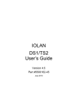
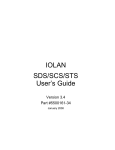
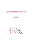
5500192-12
RPS Series
Remote Power Switches
Models Covered:
RPS820
RPS830
RPS1620H
RPS1630H
Quick Start Guide
Warnings and Cautions:
Installation Instructions
SECURE RACKING
If Secure Racked units are installed in a closed or multi-unit rack assembly, they may require further
evaluation by Certification Agencies. The following items must be considered.
1. The ambient within the rack may be greater than room ambient. Installation should be such
that the amount of air flow required for safe operation is not compromised. The maximum
temperature for the equipment in this environment is 45°C. Consideration should be given to the
maximum rated ambient.
2. Installation should be such that a hazardous stability condition is not achieved due to
uneven loading.
INPUT SUPPLY
Check nameplate ratings to assure there is no overloading of supply circuits that could have an effect
on overcurrent protection and supply wiring.
GROUNDING
Reliable earthing of this equipment must be maintained. Particular attention should be given
to supply connections when connecting to power strips, rather than direct connections to the branch
circuit.
No Serviceable Parts Inside; Authorized Service Personnel Only
Do not attempt to repair or service this device yourself. Internal components must be serviced by
authorized personnel only.
• Shock Hazard - Do Not Enter
Disconnect Power
If any of the following events are noted, immediately disconnect the unit from the outlet and contact
qualified service personnel:
1. If the power cord becomes frayed or damaged.
2. If liquid has been spilled into the device or if the device has been exposed to rain or water.
Two Power Supply Cables
Note that this unit includes two separate power circuits, with a power supply cable for each
circuit. Before attempting to service or remove this unit, please make certain that both power cables
are disconnected.
1. Introduction
This Quick Start Guide describes how to set up the Perle Remote Power Switch
(RPS) with your IOLAN Device Server. If you are using the RPS as a standalone, see the RPS User’s Guide. You can securely manage the power going to
any electronic device through the IOLAN Device Server. For further installation
and configuration details, please see the IOLAN SDS/SCS/STS User's Guide.
Components
You should receive the following components with your RPS unit:
• Two US Power cords with IEC power connectors
(RPS830 and RPS1630H Models Only)
• Quick Start Guide
• CDROM containing the RPS User's Guide and Quick Start Guide
• Rack Mount Brackets
• One CAT5 Cable
• RJ-45M to RJ-45F Adapter for use with IOLAN models
(Part No. 1100219-10)
• RJ-45M to RJ-45F Adapter for use with IOLAN C and CM models
(Part No. 1100320-10)
• RJ-45F to DB-9F for connecting the RPS console port to the PC COM port
(Part No. 1100300-10)
You Need to Supply
• IOLAN Device Server (if it does not have an RJ45 connector, you will need
an adapter.)
• External Power Cords (Europe and UK Only)
Page 3
RPS Series - Remote Power Switches; Quick Start Guide
2. Hardware Installation
This Quick Start Guide assumes that you have already powered up your IOLAN
Device Server according to the Device Server's Quick Start Guide.
2.1. Applying Power to the RPS
Refer to power rating nameplate on the RPS back panel, and then connect the
RPS unit to an appropriate power source. RPS830 and RPS1630H units should
be connected to a 100 to 120 VAC power supply, and RPS820 and RPS1620H
units should be connected to a 208 to 240 VAC power supply.
CAUTION: Make certain to review the safety precautions listed in
Section 4.1 in the User's Guide and at the beginning of this Quick
Start Guide.
Note that RPS units feature two separate AC inputs. Connect power supply
cables to the RPS’s Circuit "A" and Circuit "B" inlets, and then connect the
cables to an appropriate power supply. The RPS830 and RPS1630H will support
up to 20 Amps maximum per power circuit, for a total load of 40 Amps. The
RPS820 and RPS1620H will support up to 16 Amps maximum per power circuit,
for a total load of 32 Amps.
The ON LED should light, and the RDY LED should begin to flash. This
indicates that the RPS is ready to receive commands.
2.2. Connecting the Device Server to the RPS
To securely manage the RPS, configure the Device Server as follows:
1.
Set the Line Service (Profile) to Power Management for the line that is
connected to the RPS serial port.
2.
Plug the CAT5 cable into the Console port on the RPS.
3.
Connecting the Adapter to the IOLAN:
(a) For IOLAN Models: Plug the RJ-45M to RJ45F Adapter (Part No.
1100219-10) into the serial port on the IOLAN that will be configued
for Power Management. (See Section 3.)
(b) For IOLAN Model C and CM: Plug the RJ-45M to RJ45F Adapter
(Part No. 1100320-10) into the serial port on the IOLAN C and CM
that will be configured for Power Management. (See Section 3.)
4.
Connect the CAT5 cable to the Adapter.
Page 4
RPS Series - Remote Power Switches; Quick Start Guide
3. Connecting the Device Server to the RPS
To securely manage the RPS, configure the Device Server as follows:
1.
Set the Line Service to Power Management for the line that is connected to
the RPS serial port.
2.
Configure the Power Management Settings for the RPS.
See the IOLAN SDS/SCS/STS User’s Guide for information about the settings
and how to actively manage the RPS.
4. Configuring the RPS Standalone
To independently manage the RPS, through a PC COM port configure as follows:
NOTE: The default serial port parameters are set as folows: 9600,
RTS/CTS handshaking, 8 data bits, one stop bit and no parity.
1.
Plug the RJ-45F to DB9F (Part No. 1100300-10) into the COM port
on the PC.
2.
Connect the CAT5 cable to this adapter and the RJ-45 console port
on the RPS.
3.
Start your communication program on your PC (set serial port parameters as
described above.)
4.
Press [Enter]
5.
The RPS will return the RPS> command prompt.
6.
Type /h to view the command menu.
Please refer to the RPS User's Guide for instructions regarding other methods to
connect to the RPS.
Page 5
RPS Series - Remote Power Switches; Quick Start Guide
5. Technical Support
Technical support information can be found at the following link:
www.perle.com/support_services/
6. Warranty/Registration
Details of the product warranty and registration process can be found by
following the appropriate links on the Remote Power Switch Product page at:
http://www.perle.com
RPS Series Quick Start Guide
Part No: 5500192-12
Copyright © Perle Systems Limited, 2011
Page 6
FCC Part 15 Regulation
This equipment has been tested and found to comply with the limits for a Class A digital device,
pursuant to Part 15 of the FCC rules. These limits are designed to provide reasonable protection
against harmful interference in a residential installation. This equipment generates, uses, and can
radiate radio frequency energy, and if not installed and used in accordance with the instructions, may
cause harmful interference to radio communications. However, there is no guarantee that interference
will not occur in a particular installation. If this equipment does cause harmful interference to radio
or television reception, which can be determined by turning the equipment off and on, the user is
encouraged to try to correct the interference by one or more of the following measures:
• Reorient or relocate the receiving antenna.
• Increase the separation between the equipment and receiver.
• Plug the equipment into an outlet on a circuit that is different from the one used by the receiver.
• Consult the dealer or an experienced radio/TV technician for help.
This device complies with Part 15 of the FCC rules. Operation of this device is subject to the
following conditions: (1) This device may not cause harmful interference, and (2) this device must
accept any interference that may cause undesired operation.
WARNING: Changes or modifications to this unit not expressly approved by the
party responsible for compliance could void the user’s authority to operate the
equipment
EMC, Safety, and R&TTE Directive Compliance
The CE mark is affixed to this product to confirm compliance with the following European
Community Directives:
• Council Directive 89/336/EEC of 3 May 1989 on the approximation of the laws of Member
States relating to electromagnetic compatibility;
and
• Council Directive 73/23/EEC of 19 February 1973 on the harmonization of the laws of
Member States relating to electrical equipment designed for use within certain voltage limits;
and
• Council Directive 1999/5/EC of 9 March on radio equipment and telecommunications terminal
equipment and the mutual recognition of their conformity.
13719-C