1
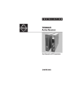
I N S T A L L A T I O N
TW3001AR
Active Receiver
Single Channel for UTP Transmission
C1666M-A (4/06)
Important Safety Instructions
1. Read these instructions.
2. Keep these instructions.
3. Heed all warnings.
4. Follow all instructions.
5. Do not use this apparatus near water.
6. Clean only with dry cloth.
7. Do not block any ventilation openings. Install in accordance with the manufacturer’s
instructions.
8. Do not install near any heat sources such as radiators, heat registers, stoves, or other
apparatus (including amplifiers) that produce heat.
9. Do not defeat the safety purpose of the polarized or grounding-type plug. A polarized plug has
two blades with one wider than the other. A grounding plug has two blades and a third
grounding prong. The wide blade or the third prong are provided for your safety. If the
provided plug does not fit into your outlet consult an electrician for replacement of the
obsolete outlet.
10. Protect the power cord from being walked on or pinched particularly at plugs, convenience
receptacles, and the points where they exit from the apparatus.
11. Only use attachments/accessories specified by the manufacturer.
12. Use only with the cart, stand, tripod, bracket, or table specified by the manufacturer, or sold
with the apparatus. When a cart is used, use caution when moving the cart/apparatus
combination to avoid injury from tip-over.
13. Refer all servicing to qualified service personnel. Servicing is required when the apparatus
has been damaged in any way, such as power-supply cord or plug is damaged, liquid has been
spilled or objects have fallen into the apparatus, the apparatus has been exposed to rain or
moisture, does not operate normally, or has been dropped.
14. Apparatus shall not be exposed to dripping or splashing and that no objects fi lled with liquids,
such as vases shall be placed on the apparatus.
15. WARNING: To reduce the risk of fire or electric shock, do not expose this apparatus to rain or
moisture.
16. Installation should be done only by qualified personnel and conform to all local codes.
17. Unless the unit is specifically marked as a NEMA Type 3, 3R, 3S, 4, 4X, 6, or 6P enclosure, it is
designed for indoor use only and it must not be installed where exposed to rain and moisture.
18. Use only installation methods and materials capable of supporting four times the maximum
specified load.
19. A CCC-approved power cord must be used to power this equipment when used in China.
C1666M-A (4/06)
3
Regulatory Notices
This device complies with Part 15 of the FCC Rules. Operation is subject to the following two
conditions: (1) this device may not cause harmful interference, and (2) this device must accept any
interference received, including interference that may cause undesired operation.
RADIO AND TELEVISION INTERFERENCE
This equipment has been tested and found to comply with the limits of a Class A digital device,
pursuant to Part 15 of the FCC rules. These limits are designed to provide reasonable protection
against harmful interference when the equipment is operated in a commercial environment.
This equipment generates, uses, and can radiate radio frequency energy and, if not installed and used
in accordance with the instruction manual, may cause harmful interference to radio communications.
Operation of this equipment in a residential area is likely to cause harmful interference in which case
the user will be required to correct the interference at his own expense.
Changes and Modifications not expressly approved by the manufacturer or registrant of this
equipment can void your authority to operate this equipment under Federal Communications
Commission’s rules.
In order to maintain compliance with FCC regulations shielded cables must be used with this
equipment. Operation with non-approved equipment or unshielded cables is likely to result in
interference to radio and television reception.
This Class A digital apparatus complies with Canadian ICES-003.
Cet appareil numérique de la classe A est conforme à la norme NMB-003 du Canada.
The materials used in the manufacture of this document and its components are compliant to the
requirements of Directive 2002/95/EC.
This equipment contains electrical or electronic components that must be recycled properly to
comply with Directive 2002/96/EC of the European Union regarding the disposal of waste electrical
and electronic equipment (WEEE). Contact your local dealer for procedures for recycling this
equipment.
4
C1666M-A (4/06)
Description
The TW3001AR is a single-channel active receiver that can receive live video over unshielded twisted
pair (UTP) cable.
The adaptive technology in the TW3001AR automatically adjusts the low, medium and high frequency
components of the video signal allowing for the best possible video transmission. The adaptive
technology eliminates the need for manual adjustment by automatically adjusting to provide the most
favorable video transmission depending on cable length needed. The unit has been optimized for use
with Cat5e and Cat6 cable, although Cat3 and Cat5 cable can be used for shorter distances.
The DIP switch on the bottom of the TW3001AR allows you to override the adaptive technology and
manually select the cable distance. Switches 1, 2, 3, and 4 can be set to 4,000 feet (1,219 meters),
3,000 feet (914 meters), 2,000 feet (610 meters), and 1,000 feet (305 meters), respectively. Switch 5
can be set to high mode and low mode.
There are two ways you can power the TW3001AR. You can power it by installing it into an
RK5000PS-3U using the 4-pin connector. For stand-alone power, you can use the 2-pin power
connector and use either a 12 VDC power supply (supplied) or a 24 VAC power supply.
The following features are found on the TW3001AR:
•
Full motion color/black and white video up to 4,000 feet (1,219 meters) with Cat5e or Cat6
•
Supports Coaxitron control (PTZ control signals) up to 750 feet (229 meters)
•
Compatible with all Pelco twisted pair equipped cameras, enclosures, and domes
•
Built-in surge suppression
•
Easy termination with removable UTP connector
•
Supports NTSC, PAL, and SECAM
•
Can be mounted into a Pelco fiber rack, wall mount base kit, or wall clip
C1666M-A (4/06)
5
PARTS OF THE RECEIVER
MODEL
SN
FREQ
4
5
AND (2) THIS DEVICE MUST ACCEPT ANY INTERFERENCE RECEIVED,
INCLUSING INTERFERENCE THAT MAY CAUSE UNDESIRED OPERATION.
THIS DEVICE COMPLIES WITH PART 15 OF THE FCC RULES.
OPERATION IS SUBJECT TO THE FOLLOWING TWO CONDITIONS:
(1) THIS DEVICE MAY NOT CAUSE HARMFUL INTERFERENCE,
3
2
1
+
-
W
Figure 1. TW3001AR Parts
6
Rubber Feet (4): For placing unit on a flat surface, such as a desk or shelf.
Status LED: Lights red when there is no UTP video being received. Lights green when there is
UTP video being received. Flashes amber when Coaxitron pan/tilt/zoom (PTZ) control
commands are being received.
Pelco Badge: Lights blue to indicate power when using either the 4-pin rack power connector
or the 2-pin power connector.
Rack Power Connector: 4-pin, power from RK5000PS-3U.
Power Connector (3.5 mm): 2-pin; stand-alone power, 12 VDC or 24 VAC.
UTP Connector (2.5 mm): 2-pin connector with removable mating connector.
BNC Connector: Coaxial output.
DIP Switch: Override the adaptive technology with the manual selection of cable distance
(1,000-4,000 feet or 305-1,219 meters). Switch 5 is used for selecting high mode or low mode.
C1666M-A (4/06)
Installation
Make sure all parts are present for the unit.
1
1
1
1
Universal power supply (Part #PS04-1502-0512G)
Wall clip
2-pin power connector
2-pin UTP connector
MOUNTING
The TW3001AR receiver is 3 rack units high and can be mounted into a fiber rack, onto a wall using
a fiber wall mount kit or into the supplied wall clip.
USING A RACK
You can mount a TW3001AR into either an RK5000PS-3U (for power) or an RK5000-3U. For additional
mounting information, refer to the RK5000PS-3U/RK5000-3U Fiber Rack Mount Chassis Installation
manual.
USING WALL MOUNT KITS
The optional WM5001-3U wall mount base kit allows attachment of a single TW3001AR to a wall.
Up to two WM5001-3UEXP wall mount expansion kits can be used to allow attachment of two
additional receivers to the wall. For additional information, refer to the Fiber Wall Mount Kits
Installation manual.
C1666M-A (4/06)
7
USING A WALL CLIP
To attach the TW3001AR receiver to a wall using the supplied wall clip, refer to Figure 2 and do the
following:
1. Attach the wall clip to a wall using two screws (not supplied).
2. Slide the receiver into the clip until the two holes on the bottom of the receiver align with the
two holes on the lower flange of the clip.
3. Attach the receiver to the clip using the two Phillips pan head screws provided with the clip.
UPPER
FLANGE
VERTICAL
MOUNTING HOLE (2)
HORIZONTAL
MOUNTING HOLE (2)
TW3001AR
SCREW, PHILLIPS
PAN HEAD WITH
LOCK WASHER (2)
WALL CLIP
LOWER
FLANGE
Figure 2. Mounting the TW3001AR Using the Wall Clip
8
C1666M-A (4/06)
SETTING THE DIP SWITCHES
You can override the adaptive technology by manually adjusting switches 1-4 on the DIP Switch.
The factory default switch positions are shown in Figure 3. Switches 1-4 are set to AUTO and
Switch 5 is set to High Mode.
Figure 3. Default Switch Positions
If you want to transmit video over 4,000 feet (1,219 meters) of UTP cable, set switch 1 to 4K. Set
switch 2 to 3K if you want a distance of 3,000 feet (914 meters), switch 3 to 2K if you want a distance
of 2,000 feet (610 meters), and switch 4 to 1K if you want a distance of 1,000 feet (305 meters).
You can set only one distance at a time.
With switch 5 you can select high mode or low mode. High mode is the default position and is used
when video is 1Vp-p. Low mode is used when video is less than 1Vp-p.
C1666M-A (4/06)
9
APPLICATIONS
You can connect the TW3001AR active receiver to transmitters, such as the TW3001P passive transceiver and the TW3001AT active transmitter, and to Pelco UTP cameras, such as the CC3710/CC3610
Series. Although you can connect these products using an unshielded twisted pair Cat3 and Cat5
cable, Cat5e and Cat6 are recommended for the best video performance.
Always connect the UTP wires on the Cat cable from + to + and from - to -. For example, if you connect
the blue wire to the + on the TW3001AR make sure you connect the other end of the blue wire to the
+ on the transmitter.
Table A shows the maximum cable distance with Coaxitron or video only when connecting the
TW3001AR to a TW3001P passive transceiver with a particular type of Cat cable.
Table A. Cable Distance with TW3001P
Cable Type
Cat3e
Maximum Distance Maximum Distance
(with Coaxitron)
(video only)
750 ft (229 m)
1,500 ft (457 m)
Cat5e
750 ft (229 m)
3,000 ft (914 m)
Cat5e
750 ft (229 m)
4,000 ft (1,219 m)
Cat6e
750 ft (229 m)
4,000 ft (1,219 m)
NOTE: Cat5e cable is recommended for the best video performance.
Table B shows the minimum size for a single wire and stranded wire.
Table B. Wire Gauge
Wire Gauge (minimum size)
10
Single Wire (solid)
24 AWG (0.25 mm2)
Stranded Wire (flexible)
24 AWG (1.0 mm2)
C1666M-A (4/06)
Figure 4 shows a TW3001AR connected to a UTP camclosure.
TW3001AR
POWER FROM RK5000PS-3U
OR
12 VDC OR 24 VAC
POWER SUPPLY
+
-
CAMCLOSURE
UTP
BLUE WIRE =
MONITOR
GRAY WIRE =
Figure 4. TW3001AR Connected to a UTP Camclosure
C1666M-A (4/06)
11
Figure 5 shows a TW3001AR connected to a UTP fixed camera.
TW3001AR
POWER FROM RK5000PS-3U
OR
12 VDC OR 24 VAC
POWER SUPPLY
+
-
FIXED CAMERA
UTP
PIN 5 +
PIN 4 -
MONITOR
10 PINS
(5-/6+)
8 PINS (4-/5+)
Figure 5. TW3001AR Connected to a UTP Fixed Camera
12
C1666M-A (4/06)
Figure 6 shows a TW3001AR connected to a UTP Spectra dome for Coaxitron PTZ control.
TW3001AR
POWER FROM RK5000PS-3U
OR
12 VDC OR 24 VAC
POWER SUPPLY
SPECTRA
+
VC-UTP BOARD
COAXITRON
UTP
VIDEO
MATRIX
MONITOR
Figure 6. TW3001AR Connected to a Spectra Dome
C1666M-A (4/06)
13
Figure 7 shows a TW3001AR connected to a TW3001P passive transceiver. The TW3001P then
connects to a non-UTP fixed camera.
TW3001AR
POWER FROM RK5000PS-3U
OR
12 VDC OR 24 VAC
POWER SUPPLY
+
-
UTP
TW3001P
DIRECT
CONNECTION
FIXED
CAMERA
MONITOR
Figure 7. TW3001AR Connected to a Single Passive Transceiver
14
C1666M-A (4/06)
Figure 8 shows a TW3001AR connected to a TW3032P passive transceiver.
TW3001AR
POWER FROM RK5000PS-3U
OR
12 VDC OR 24 VAC
POWER SUPPLY
+
-
TW3032P
UTP
MONITOR
Figure 8. TW3001AR Connected to a 32-Channel Passive Transceiver
C1666M-A (4/06)
15
Figure 9 shows a TW3001AR connected to a TW3004P passive transceiver. The TW3004P then
connects to a non-UTP fixed camera.
TW3001AR
TW3004P
POWER FROM RK5000PS-3U
12 VDC OR
24 VAC
POWER SUPPLY
OR
+
-
4
3
UTP
MONITOR
2
FIXED
CAMERA
1
Figure 9. TW3001AR Connected to a 4-Channel Passive Transceiver
16
C1666M-A (4/06)
Specifications
ELECTRICAL
Input Voltage
Power Consumption
Wire Type
Wire Category
DC Loop Resistance
Differential Capacitance
Transient Immunity
Insertion Loss
12 VDC or 24 VAC, 50-60Hz
2.5 watts
Unshielded Twisted Pair (24 AWG maximum)
Cat3 or better
52 ohms per 1,000 feet
19pF/ft max
300 W peak pulse power (8/20 US)
72 dB over; 0-8 MHz frequency range
VIDEO CHARACTERISTICS
Video Output
Format
Frequency Response
Common Mode/Differential
Mode Rejection
One BNC
NTSC, PAL, SECAM
DC to MHz
>70 dB
MECHANICAL
Connectors
BNC
4-Pin Connector
2-Pin Connector (2.5 mm)
2-Pin Connector (3.5 mm)
Construction
Finish
Video output
Rack power
UTP input/output
Power
Steel
Silver
GENERAL
Operating Temperature
Relative Humidity
Data Transmission
LED Indicators
Dimensions
Unit Weight
C1666M-A (4/06)
32° to 167°F (0° to 75°C)
0 to 90%, noncondensing
Supports Coaxitron up to 750 feet
Pelco badge (blue); status LED (red, green, flashing amber)
4.81” H x 1.08” W x 8.75” D
(12.22 x 2.74 x 22.23 cm)
1.0 lb (0.45 kg)
17
18
C1666M-A (4/06)
PRODUCT WARRANTY AND RETURN INFORMATION
WARRANTY
Pelco will repair or replace, without charge, any merchandise proved defective in material or workmanship for a period of one year after the date of
shipment.
Exceptions to this warranty are as noted below:
• Five years on FR/FT/FS Series fiber optic products and TW3000 Series unshielded twisted pair transmission products.
• Three years on Genex® Series products (multiplexers, server, and keyboard).
• Three years on Camclosure® and fixed camera models, except the CC3701H-2, CC3701H-2X, CC3751H-2, CC3651H-2X, MC3651H-2, and
MC3651H-2X camera models, which have a five-year warranty.
• Three years on PMCL200/300/400 Series LCD monitors.
• Two years on standard motorized or fixed focal length lenses.
• Two years on Legacy®, CM6700/CM6800/CM9700 Series matrix, and DF5/DF8 Series fixed dome products.
• Two years on Spectra®, Esprit®, ExSite™, and PS20 scanners, including when used in continuous motion applications.
• Two years on Esprit® and WW5700 Series window wiper (excluding wiper blades).
• Two years (except lamp and color wheel) on Digital Light Processing (DLP®) displays. The lamp and color wheel will be covered for a period of
90 days. The air filter is not covered under warranty.
• Eighteen months on DX Series digital video recorders, NVR300 Series network video recorders, and Endura™ Series distributed network-based video
products.
• One year (except video heads) on video cassette recorders (VCRs). Video heads will be covered for a period of six months.
• Six months on all pan and tilts, scanners or preset lenses used in continuous motion applications (that is, preset scan, tour and auto scan modes).
Pelco will warrant all replacement parts and repairs for 90 days from the date of Pelco shipment. All goods requiring warranty repair shall be sent freight
prepaid to Pelco, Clovis, California. Repairs made necessary by reason of misuse, alteration, normal wear, or accident are not covered under this
warranty.
Pelco assumes no risk and shall be subject to no liability for damages or loss resulting from the specific use or application made of the Products. Pelco’s
liability for any claim, whether based on breach of contract, negligence, infringement of any rights of any party or product liability, relating to the Products
shall not exceed the price paid by the Dealer to Pelco for such Products. In no event will Pelco be liable for any special, incidental or consequential
damages (including loss of use, loss of profit and claims of third parties) however caused, whether by the negligence of Pelco or otherwise.
The above warranty provides the Dealer with specific legal rights. The Dealer may also have additional rights, which are subject to variation from state
to state.
If a warranty repair is required, the Dealer must contact Pelco at (800) 289-9100 or (559) 292-1981 to obtain a Repair Authorization number (RA), and
provide the following information:
1. Model and serial number
2. Date of shipment, P.O. number, Sales Order number, or Pelco invoice number
3. Details of the defect or problem
If there is a dispute regarding the warranty of a product which does not fall under the warranty conditions stated above, please include a written
explanation with the product when returned.
Method of return shipment shall be the same or equal to the method by which the item was received by Pelco.
RETURNS
In order to expedite parts returned to the factory for repair or credit, please call the factory at (800) 289-9100 or (559) 292-1981 to obtain an authorization
number (CA number if returned for credit, and RA number if returned for repair).
All merchandise returned for credit may be subject to a 20% restocking and refurbishing charge.
Goods returned for repair or credit should be clearly identified with the assigned CA or RA number and freight should be prepaid. Ship to the appropriate
address below.
If you are located within the continental U.S., Alaska, Hawaii or Puerto Rico, send goods to:
Service Department
Pelco
3500 Pelco Way
Clovis, CA 93612-5699
If you are located outside the continental U.S., Alaska, Hawaii or Puerto Rico and are instructed to return goods to the USA, you may do one of the
following:
If the goods are to be sent by a COURIER SERVICE, send the goods to:
Pelco
3500 Pelco Way
Clovis, CA 93612-5699 USA
If the goods are to be sent by a FREIGHT FORWARDER, send the goods to:
Pelco c/o Expeditors
473 Eccles Avenue
South San Francisco, CA 94080 USA
Phone: 650-737-1700
Fax: 650-737-0933
REVISION HISTORY
Manual #
C1666M
C1666M-A
Date
1/06
4/06
Comments
Original version.
Added high mode and low mode information.
Pelco, the Pelco logo, Camclosure, Esprit, Genex, Legacy, and Spectra are registered trademarks of Pelco.
Endura and ExSite are trademarks of Pelco.
DLP is a registered trademark of Texas Instruments, Inc.
©Copyright 2006, Pelco.
All rights reserved.
Worldwide Headquarters
3500 Pelco Way
Clovis, California 93612 USA
USA & Canada
Tel: 800/289-9100
Fax: 800/289-9150
International
Tel: 1-559/292-1981
Fax: 1-559/348-1120
www.pelco.com
ISO9001
United States | Canada | United Kingdom | The Netherlands | Singapore | Spain | Scandinavia | France | Middle East