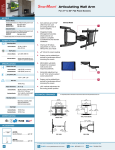
1
Installation and Assembly:
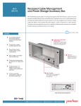
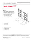
Recessed Cable Management and Power Storage
Accessory Box
Models: IBA2AC, IBA2AC-W
2300 White Oak Circle • Aurora, Il 60502 • (800) 865-2112 • Fax: (800) 359-6500 • www.peerlessmounts.com
ISSUED: 01-15-11 SHEET #: 120-9104-2 06-13-11
Note: Read entire instruction sheet before you start installation and assembly.
WARNING
• Do not begin to install your Peerless product until you have read and understood the instructions and warnings
contained in this Installation Sheet. If you have any questions regarding any of the instructions or warnings, for US
customers please call Peerless customer care at 1-800-865-2112, for all international customers, please contact
your local distributor.
• This product should only be installed by someone of good mechanical aptitude, has experience with basic building
construction, and fully understands these instructions.
• Make sure that the supporting surface will safely support the combined load of the equipment and all attached
hardware and components.
• If mounting to wood wall studs, make sure that mounting screws are anchored into the center of the studs. Use of
an "edge to edge" stud finder is highly recommended.
• Tighten screws firmly, but do not overtighten. Overtightening can damage the items, greatly reducing their holding
power.
• This product is intended for indoor use only. Use of this product outdoors could lead to product failure and personal
injury.
WALL CONSTRUCTION
HARDWARE REQUIRED
• Wood Stud
• Metal Stud
Included
Do not attach except with Peerless accessory kit ACC415;
Contact Customer Service for Peerless accessory kit ACC415
Contact Qualified Professional
Do not attach except with Peerless accessory kit ACC415;
Contact Customer Service for Peerless accessory kit ACC415
Contact Qualified Professional
• Brick
• Drywall
• Other or unsure?
Tools Needed for Assembly
•
•
•
•
•
stud finder ("edge to edge" stud finder is recommended)
phillips screwdriver
drill
3/16" (5mm) drill bit for wood studs
level
Table of Contents
Parts List................................................................................................................................................................................. 3
Installation to Wood Wall ........................................................................................................................................................ 4
Electrical Outlet Installation .................................................................................................................................................... 5
Cable Management ................................................................................................................................................................6
2 of 7
Visit the Peerless Web Site at www.peerlessmounts.com
ISSUED: 01-15-11 SHEET #: 120-9104-2 06-13-11
For customer care call 1-800-865-2112
Before you begin, make sure all parts shown are included with your product.
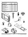
Parts List
A
B
C
D
E
F
G
H
I
J
K
Description
in-wall box
1-1/2" wood screw
4mm security driver
cable bushing
cable management clips
plastic finishing cap
cable tie
access plate
M5 x 6mm phillips screw
surge suppressor
outlet box
IBA2AC
Qty. Part #
1
120-P1185
4
500-1090
1
560-1133
1
590-1295
2
590-1166
1
590-1123
2
590-1168
1
120-P1187
5
520-1023
1
600-0190
1
600-0191
IBA2AC-W
Part #
120-2185
500-4090
560-1133
590-2295
590-1166
590-2123
590-1168
120-2187
520-2214
600-2190
600-0191
Parts may appear slightly different than illustrated.
A
D
C
B
I
G
E
H
F
K
J
3 of 7
Visit the Peerless Web Site at www.peerlessmounts.com
ISSUED: 01-15-11 SHEET #: 120-9104-2 06-13-11
For customer care call 1-800-865-2112
Installation to Wood Stud Wall
WARNING
• Installer must verify that the supporting surface will safely support the combined load of the equipment and all
attached hardware and components.
• Tighten wood screws so that in-wall box is firmly attached, but do not overtighten. Overtightening can damage the
screws, greatly reducing their holding power.
• Never tighten in excess of 80 in. • lb (9 N.M.).
• Make sure that mounting screws are anchored into the center of the stud. The use of an "edge to edge" stud finder
is highly recommended.
• Hardware provided is for attachment of mount through standard thickness drywall or plaster into wood studs.
Installers are responsible to provide hardware for other types of mounting situations.
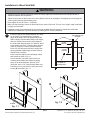
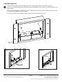
1
In-wall box (A) can be installed between two studs
16" off center. Use a stud finder to locate the
edges of the studs. Use of an edge-to-edge stud
finder is highly recommended. Based on its edges,
draw two vertical lines down the inside edges of
the studs. Mark desired center of in-wall box. Draw
a horizontal line 4-15/16" (125mm) above desired
center of in-wall box. Draw a second horizontal
line 9-3/4" (247mm) below this line to outline wall
opening between inside edges of studs. Remove
drywall inside cut outline.
STUDS
TOP LINE OF CUT
OUTLINE
13-1/8"
(333mm)
4-15/16"
(125mm)
9-3/4"
(247mm)
Insert in-wall box (A) into wall until flange is flush
with drywall as shown in fig. 1.1.
Level in-wall box, and mark center of the four
mounting holes. Make sure that the mounting
holes are on stud centerlines. Drill four 3/16"
(5mm) dia. holes 1-1/2" (38mm) deep. Make sure
in-wall box is level, and secure it using four wood
screws (B) as shown in fig. 1.2.
CENTER OF
IN-WALL BOX
A
B
fig. 1.2
FLANGE
fig. 1.1
4 of 7
Visit the Peerless Web Site at www.peerlessmounts.com
ISSUED: 01-15-11 SHEET #: 120-9104-2 06-13-11
For customer care call 1-800-865-2112
Electrical Outlet Installation
2
Remove knockout from access plate (H).
Attach surge protector (J) to outlet box (K) with access plate (H) in between using two surge protector screws.
Attach cover plate to surge protector using two cover plate screws.
NOTE: Service of an electrical gang box and wiring shall be performed by a qualified service personnel in
accordance with the NEC.
ACCESS PLATE
KNOCKOUT
H
COVER PLATE
SCREWS
COVER PLATE
J
SURGE
PROTECTOR
SCREWS
H
K
5 of 7
Visit the Peerless Web Site at www.peerlessmounts.com
ISSUED: 01-15-11 SHEET #: 120-9104-2 06-13-11
For customer care call 1-800-865-2112
Cable Management
3
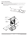
Attach access plate (H) to in-wall box (A) with five M5 x 8mm phillips screws (I) as shown in figure 3.1.
Insert up to two cable management clips (E) into the desired positions in the in-wall box as shown in figure 3.2 for
routing cables.
Insert cable bushing (D) into in-wall box for routing cables through in-wall box. Plastic finishing cap (F) may also
be used if cable management is unnecessary.
Use cable ties (G) to secure cables to cable management clips as shown in figure 3.3.
I
H
fig. 3.1
fig. 3.2
fig. 3.3
E
CABLES
G
D or F
6 of 7
Visit the Peerless Web Site at www.peerlessmounts.com
ISSUED: 01-15-11 SHEET #: 120-9104-2 06-13-11
For customer care call 1-800-865-2112
© 2011, Peerless Industries, Inc. All rights reserved.
All other brand and product names are trademarks or registered trademarks of their respective owners.
LIMITED FIVE-YEAR WARRANTY
Peerless Industries, Inc. (“Peerless”) warrants to original end-users of Peerless® products will be free from defects in material and workmanship, under normal
use, for a period of five years from the date of purchase by the original end-user (but in no case longer than six years after the date of the product’s manufacture).
At its option, Peerless will repair or replace, or refund the purchase price of, any product which fails to conform with this warranty.
In no event shall the duration of any implied warranty of merchantability or fitness for a particular purpose be longer than the period of the applicable
express warranty set forth above. Some states do not allow limitations on how long an implied warranty lasts, so the above limitation may not apply to you.
This warranty does not cover damage caused by (a) service or repairs by the customer or a person who is not authorized for such service or repairs by Peerless,
(b) the failure to utilize proper packing when returning the product, (c) incorrect installation or the failure to follow Peerless’ instructions or warnings when installing,
using or storing the product, or (d) misuse or accident, in transit or otherwise, including in cases of third party actions and force majeure.
In no event shall Peerless be liable for incidental or consequential damages or damages arising from the theft of any product, whether or not secured
by a security device which may be included with the Peerless® product. Some states do not allow the exclusion or limitation of incidental or consequential
damages, so the above limitation or exclusion may not apply to you.
This warranty is in lieu of all other warranties, expressed or implied, and is the sole remedy with respect to product defects. No dealer, distributor, installer or other
person is authorized to modify or extend this Limited Warranty or impose any obligation on Peerless in connection with the sale of any Peerless® product.
This warranty gives specific legal rights, and you may also have other rights which vary from state to state.
www.peerlessmounts.com
7 of 7
Visit the Peerless Web Site at www.peerlessmounts.com
© 2011 Peerless Industries, Inc.
ISSUED: 01-15-11 SHEET #: 120-9104-2 06-13-11
For customer care call 1-800-865-2112