1
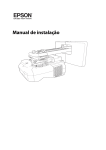
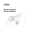
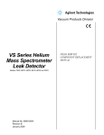
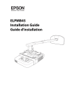
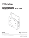
Installation and Assembly:
DUKANE PROJECTOR SHORT THROW WALL ARM
Model: UST-WALLARM3
PROJECTOR POSITION FOR
60" - 70" SCREEN SIZE
PROJECTOR POSITION FOR
70" - 100" SCREEN SIZE
430-User Guide UST-WALLARM3-00
WARNING
• Do not begin to install your Peerless product until you have read and understood the instructions and warnings
contained in this Installation Sheet. If you have any questions regarding any of the instructions or warnings, for US
customers please call Peerless customer care at 1-800-865-2112, for all international customers, please contact
your local distributor.
• This product should only be installed by someone of good mechanical aptitude, has experience with basic building
construction, and fully understands these instructions.
• Make sure that the supporting surface will safely support the combined load of the equipment and all attached
hardware and components.
• Never exceed the Maximum Load Capacity. See page one.
• If mounting to wood wall studs, make sure that mounting screws are anchored into the center of the studs. Use of
an “edge to edge” stud finder is highly recommended.
• Always use an assistant or mechanical lifting equipment to safely lift and position equipment.
• Tighten screws firmly, but do not overtighten. Overtightening can damage the items, greatly reducing their holding
power.
• This product is intended for indoor use only. Use of this product outdoors could lead to product failure and personal
injury.
• This product was designed to be installed on the following wall construction only;
WALL CONSTRUCTION
HARDWARE REQUIRED
• Wood Stud Included
• Wood Beam
Included
• Solid Concrete
Included
• Cinder Block
Included
• Brick
Contact Qualified Professional Contact Qualified Professional
• Other or unsure?
Tools Needed for Assembly
• stud finder ("edge to edge" stud finder is recommended)
• phillips screwdriver
• drill
• 1/4" bit for concrete and cinder block wall
• 5/32" bit for wood stud wall
• level
• masking tape
• 6 mm allen wrench
Table of Contents
Parts List.................................................................................................................................................................................3
Wall Plate Location Template..................................................................................................................................................4
Installation to Single Wood Stud Wall......................................................................................................................................5
Installation to Solid Concrete and Cinder Block Wall..............................................................................................................6
Attaching adapter plate assembly to projector........................................................................................................................7
Installation using wall arm bracket .........................................................................................................................................8
Installation using wall arm bracket and extension bracket ............................................................................................... 9-10
Adjusting the Projector.................................................................................................................................................... 12-13
Fasten wall arm cover.......................................................................................................................................................... 14
2 of 14
ISSUED:07-25-11 SHEET #: 125-9225-1
Before you start make sure all parts listed are included with your product.
PARTS LIST
A
B
C
D
E
F
G
H
I
J
K
L
M
N
O
P
Q
R
S
T
U
Description
adapterplateassembly
extensionbracket
wallarmbracket
wallplate
wallplatecover
projectortiltplate
cablemanagementbracket
projectorattachmentbracket
shimspacerplate
#14x2.5"woodscrew
concreteanchor
M4x8mmsocketpinserratedwasherheadscrew
M6x10mmsocketpinscrew
#8x3/8"sheetmetalscrew
#10flatblackwasher
M5x8mmpanheadblackscrew
4mmallenwrench
M5x20mmsocketpinserratedwasherheadscrew
wallarmcap
M5x10mmsocketpinserratedwasherheadscrew
extensioncap
A
Qty.
Part #
1
056-2051
1
056-2039
1
056-2045
1
056-2046
1
056-2047
1
056-2042
2
056-2050
1
056-2048
1
056-2049
4 5S1-015-C04
4
590-0230
4
510-2005
4
520-2255
2
500-2008
4
540-9400
4
570-0005
1
560-9646
5
510-2065
1
056-2054
6
510-2063
1
590-2337
B
Some parts may appear slightly different than illustrated.
C
D
F
E
G
I
J
S
K
U
H
M
L
P
T
3 of 14
N
O
Q
R
ISSUED:07-25-11 SHEET #: 125-9225-1
Wall Plate Location
Determine and mark the top edge of the
1
screen
active image.
NOTE: Make sure to leave adequate space above the top edge of the active image for the wall arm and projector to be installed. Approximate dimension (23.0")
Using your mark for the top edge of active image determine
dimension B to locate the bottom wall plate (D)
mounting hole.
A = Board size / diagonal active image size
B = Distance from the top edge of the active image to the bottom
mounting hole of wall plate (D).
C = Distance from the top edge of the active image to the bottom
edge of wall plate (D).
SCREEN ACTIVE IMAGE
BOTTOM
MOUNTING HOLE
D
MANUFACTURER
Hitachi Starboard
Hitachi Starboard
MODEL
Trio 88
Trio 77
A
88
77
B
13.90
11.68
C
11.90
9.68
Mimio
Mimio
Mimio
HD90
Board 80
Board 100
88
78
98
13.90
11.82
14.60
11.90
9.82
12.60
Polyvision/ENO
Polyvision/ENO
Polyvision/ENO
Polyvision/ENO
Polyvision/ENO
Polyvision/ENO
Polyvision/ENO
Polyvision/ENO
TS620
TSL620
2610
2650
2650
2810
2850
2850
77.8
77.8
78
75‐16:10
75‐4:3
96
93‐16:10
93‐4:3
11.79
11.79
11.82
12.00
11.40
15.10
14.65
13.85
9.79
9.79
9.82
10.00
9.40
13.10
12.65
11.85
Promethean
Promethean
Promethean
Promethean
Promethean
Promethean
Promethean
Promethean
Promethean
Promethean
587 Pro
387
387 Pro
595 Pro
395
395 Pro
164
378
378 Pro
178
87
87
87
95
95
95
64
78
78
78
13.75
13.75
13.75
14.95
14.95
14.95
9.86
11.82
11.82
11.82
11.75
11.75
11.75
12.95
12.95
12.95
7.86
9.82
9.82
9.82
Smart
Smart
Smart
Smart
Smart
Smart
885
685
690
660
880
680
87
87.13
94
64
77
77
13.75
13.76
14.80
9.86
11.68
11.68
11.75
11.76
12.80
7.86
9.68
9.68
AMOUNT OF VERTICAL ADJUSTMENT
.7
PROJECTOR MIRROR
2.0"
8.9"
7.5"
B
.7
C
TOP OF ACTIVE IMAGE
A
BOARD THICKNESS
SCREEN CENTER
4 of 14
ISSUED:07-25-11 SHEET #: 125-9225-1
Installation to Single Wood Stud Wall
WARNING
• Installer must verify that the supporting surface will safely support the combined load of the equipment and all
attached hardware and components.
• Tighten wood screws so that wall plate is firmly attached, but do not overtighten. Overtightening can damage the
screws, greatly reducing their holding power.
• Never tighten in excess of 80 in. • lb (9 N.M.).
• Make sure that mounting screws are anchored into the center of the stud. The use of an "edge to edge" stud finder
is highly recommended.
• Hardware provided is for attachment of mount through standard thickness drywall or plaster into wood studs. Installers are responsible to provide hardware for other types of mounting situations.
1
Using wall plate (D) as a template, drill four 5/32" (4 mm) dia. holes to a minimum depth of 2.5" (64 mm). Attach
wall plate (D) to centers of wood studs using four #14 x 2.5" wood screws (J) shown in figure 1.1.
Fasten wall arm bracket (C) loosely to wall plate (D) using four M5 x 8 mm pan head black screws (P), and
four #10 black washers (O).
D
DIAMOND INDICATES
TOP OF WALL PLATE
D
J
fig 1.1
P
5 of 14
O
C
fig 1.2
ISSUED:07-25-11 SHEET #: 125-9225-1
Installation to Solid Concrete or Cinder Block
WARNING
• When installing Peerless wall mounts on cinder block, verify that you have a minimum of 1-3/8" (35 mm) of actual
concrete thickness in the hole to be used for the concrete anchors. Do not drill into mortar joints! Be sure to mount
in a solid part of the block, generally 1" (25 mm) minimum from the side of the block. Cinder block must meet ASTM
C-90 specifications. It is suggested that a standard electric drill on slow setting is used to drill the hole instead of a
hammer drill to avoid breaking out the back of the hole when entering a void or cavity.
• Concrete must be 2000 psi density minimum. Lighter density concrete may not hold concrete anchor.
• Make sure that the wall will safely support four times the combined load of the equipment and all attached hardware
and components.
1
Make sure that wall arm bracket (C) is level, use it as
a template to mark four mounting holes. Drill four 5/16"
(8 mm) dia. holes to a minimum depth of 2.5" (64 mm).
Insert concrete anchors (K) in holes flush with wall as
shown (right). Place wall arm bracket over anchors and
secure with #14 x 2.5" screws (J). Level, then tighten all
fasteners.
• Never attach concrete expansion anchors to
concrete covered with plaster, drywall, or other
finishing material. If mounting to concrete surfaces
covered with a finishing surface is unavoidable),
the finishing surface must be counterbored as
shown below. Be sure concrete anchors do not
pull away from concrete when tightening screws. If
plaster/drywall is thicker than 5/8" (16 mm), custom
fasteners must be supplied by installer.
CUTAWAY VIEW
plaster/
dry wall
K
3
• Always attach concrete expansion anchors directly
to load-bearing concrete.
Tighten all fasteners.
SO
LID
CO
K
CORRECT
concrete
wall
plate
C
Place plate (AA) over anchors (EE) and secure with screws (DD).
• Never tighten in excess of 80 in. • lb (9 N.M.).
concrete
Drill holes and insert anchors (K).
J
• Tighten screws so that wall plate is firmly attached,
but do not overtighten. Overtightening can damage
screws, greatly reducing their holding power.
wall
plate
K
2
WARNING
INCORRECT
concrete
surface
1
NC
RE
TE
CI
ND
ER
BL
OC
C
plaster/
dry wall
fig 1.4
J
6 of 14
ISSUED:07-25-11 SHEET #: 125-9225-1
K
2
Remove knobs and M10 washers from top of
adapter plate assembly (A).
3
Place projector tilt plate (F) onto projector and
secure using four M4 x 8 mm socket pin serrated
washer head screws (L). L
KNOBS
SHORT FLANGE
OPPOSITE THE
PROJECTOR
LENS F
M10 WASHERS
UPPER ADAPTER PLATE
FRONT OF
PROJECTOR
MOUNTING LOCATIONS
A
FRONT OF
PROJECTOR
LOWER ADAPTER PLATE
4
Secure lower adapter plate onto projector tilt plate (F) using four M6 x 10 mm socket pin screws (M).
Re-fasten knobs and M10 washers from top of adapter plate assembly (A). KNOBS
A
M
M10 WASHERS
UPPER ADAPTER
PLATE
UPPER ADAPTER
PLATE HOLES
LOWER ADAPTER PLATE
F
NOTE: MAKE SURE THAT
UPPER ADAPTER PLATE
HOLES ARE CENTERED
WITH PROJECTOR LENS
7 of 14
ISSUED:07-25-11 SHEET #: 125-9225-1
5
Fasten two M5 x 20 mm socket pin serrated
washer head screws (R) into top of adapter
plate assembly (A) leaving 3/8" of exposed
thread as shown below. 6
Fasten one M5 x 20 mm socket pin serrated washer
head screws (R) into top of projector attachment
bracket (H) leaving no exposed thread on bottom of
bracket as shown below. R
R
3/8"
H
R
A
H
FLUSH WITH BOTTOM
7
Slide two cable management brackets (G) into channel in wall arm bracket (C) as shown below.
Slide wall plate cover (E) onto wall arm bracket (C).
G
C
C
8
Select projector mount orientation.
E
Option 1 - PROJECTOR POSITION FOR 60" - 70" SCREEN SIZE.................PAGE 8
Option 2 - PROJECTOR POSITION FOR 70" - 100" SCREEN SIZE..............PAGE 9
8 of 14
ISSUED:07-25-11 SHEET #: 125-9225-1
PROJECTOR POSITION FOR 60" - 70" SCREEN SIZE
SKIP TO PAGE 9 IF MOUNTING WITH 70" - 100" SCREEN SIZE
Installation using Wall Arm Bracket
exposed M5 x 20 mm socket pin serrated washer head screws (R) on top of adapter plate assembly (A)
9 Attach
through slot in wall arm bracket (C) and keyholes in projector attachment bracket (H) as shown in detail 1.
Slide projector attachment bracket (H) toward wall. Once in locked position tighten all three M5 x 20 mm socket pin
serrated washer head screws (R) using security wrench (Q) as shown in detail 2.
R
H
NOTE: Verify that all screws
are in the center of the slot.
FRONT OF PROJECTOR
DETAIL 1
FRONT OF PROJECTOR
10
TIGHTEN SCREWS
FRONT OF PROJECTOR
DETAIL 2
Secure wall arm cap (S) into wall arm bracket (C) using two #8 x 3/8" sheet metal screws (N).
Route projector cables as shown. Use two cable management brackets (G) as needed.
NOTE: #8 x 3/8" sheet metal screws (N) will be shortened for production.
Fasten two M5 x 20 mm socket pin serrated washer head screws (R) into top of adapter plate assembly (A).
SKIP TO PAGE 11.
PROJECTOR CABLES
G
S
R
N
9 of 14
ISSUED:07-25-11 SHEET #: 125-9225-1
PROJECTOR POSITION FOR 70" - 100" SCREEN SIZE
Installation using Wall Arm Bracket and Extension Bracket
9
Snap extension cap (U) into extension bracket (B) in orientation as shown in figure 9.1.
Slide wall plate cover (E) onto wall arm bracket (C). Slide extension bracket (B) into wall arm bracket (C) in desired position.
C
B
B
U
FIGURE 9.1
10
FIGURE 9.2
E
Requirements for Shim Spacer
1. When the front pre-fastened M5 x 20 mm socket pin serrated washer head screw (R) of the adapter plate
assembly (A) goes through the extension bracket (B) and wall arm bracket (C).
2. When there is a gap between the bottom of the projector attachment bracket (H) and the extension bracket (B).
NOTE: If Shim spacer plate (I) is not required skip to step 11
Position exposed M5 x 20 mm socket pin serrated washer head screws (R) through slot in extension bracket (B) and
wall arm bracket (C).Position screws in keyholes in projector attachment bracket (H), and hole in shim spacer plate
(I) as shown in detail 3. Slide projector attachment bracket (H) toward wall. Once in locked position tighten all three
M5 x 20 mm socket pin serrated washer head screws (R) using security wrench (Q) as shown in detail 4.
Secure extension bracket (B) into wall arm bracket (C) and secure using four M5 x 10 mm socket pin screws (T) in
desired position. NOTE: Make sure that four M5 x 10 mm socket pin screws (T) are used. SKIP TO STEP 12.
H
NOTE: Verify that all screws
are in the center of the slot.
TIGHTEN SCREWS
R
I
T
SECOND HOLE
MAY ALSO BE
USED IF DESIRED
FRONT OF PROJECTOR
R
KEYHOLE
A
R
I
FRONT OF PROJECTOR
DETAIL 3
10 of 14
FRONT OF PROJECTOR
DETAIL 4
ISSUED:07-25-11 SHEET #: 125-9225-1
Installation using Wall Arm Bracket and Extension Bracket
Attach exposed M5 x 20 mm socket pin serrated washer head screws (R) into top of adapter plate assembly (A)
11 through slot in extension bracket (B) and keyholes in projector attachment bracket (H) as shown in detail 5.
Slide projector attachment bracket (H) toward wall. Once in locked position tighten all three M5 x 20 mm socket pin
serrated washer head screws (R) using security wrench (Q) as shown in detail 6.
Secure extension bracket (B) into wall arm bracket (C) and secure using four M5 x 10 mm socket pin screws (T)
using security wrench (Q) in desired position. NOTE: Make sure that four M5 x 10 mm socket pin screws (T)
are used. H
B
T
TIGHTEN SCREWS
R
NOTE: Verify that all screws
are in the center of the slot.
R
A
FRONT OF PROJECTOR
FRONT OF PROJECTOR
DETAIL 5
12
FRONT OF PROJECTOR
DETAIL 6
Route projector cables as shown. Use two cable management brackets (G) as needed.
Fasten two M5 x 20 mm socket pin serrated washer head screws (R) into top of adapter plate assembly (A).
PROJECTOR CABLES
B
G
C
R
FRONT OF PROJECTOR
11 of 14
ISSUED:07-25-11 SHEET #: 125-9225-1
Roll Adjustment
14
Loosen knobs on left side of projector, and tighten
knobs on right side of projector to roll projector to
the right. Reverse for projector roll to the left.
LOOSEN
TIGHTEN
DO NOT
ADJUST
SUPPORTING SURFACE NOT
SHOWN FOR CLARITY
Pitch Adjustment
Loosen knobs on front of projector, and tighten
knobs on back of projector to pitch projector
forward. Reverse for projector to pitch backward.
LOOSEN
TIGHTEN
DO NOT
ADJUST
SUPPORTING SURFACE NOT
SHOWN FOR CLARITY
12 of 14
ISSUED:07-25-11 SHEET #: 125-9225-1
Combination for Pitch and Roll Rotation
Loosen knob on back right of projector, and tighten
knob on left front of projector to pitch and rotate
projector backward to the right as shown in fig. 13.2.
Reverse for projector to pitch backward to the left.
Tighten knob on back right of projector, and loosen
knob on left front of projector to pitch and rotate
projector backward to the right as shown in fig. 13.1.
Reverse for projector to pitch backward to the left.
SUPPORTING SURFACE NOT
SHOWN FOR CLARITY
Fig. 13.1
NOTE: For more adjustment, knobs can be
turned individually
LOOSEN
Swivel Adjustment
TIGHTEN
DO NOT
ADJUST
Grip sides of projector and gently rotate to desired
position.
D
SUPPORTING SURFACE NOT
SHOWN FOR CLARITY
13 of 14
ISSUED:07-25-11 SHEET #: 125-9225-1
14
Secure wall plate cover (E) to wall arm bracket (C) using two
M5 x 10 mm socket pin serrated washer head screws (T).
Note: Adjust height of wall plate prior to fastening wall plate cover (E) for projector image location. Use security
wrench (Q) to fasten screws. T
C
E
SUPPORTING SURFACE NOT
SHOWN FOR CLARITY
14 of 14
ISSUED:07-25-11 SHEET #: 125-9225-1
© 2009 Peerless Industries, Inc. All rights reserved.
Peerless is a registered trademark of Peerless Industries, Inc.
All other brand and product names are trademarks or registered trademarks of their respective owners.