1
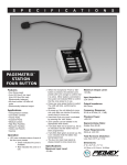
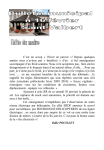
™
KB/A 30
KEYBOARD/ACOUSTIC
AMPLIFIER
OPERATING GUIDE
R
Intended to alert the user to the presence of uninsulated “dangerous voltage” within the product’s
enclosure that may be of sufficient magnitude to constitute a risk of electric shock to persons.
Intended to alert the user of the presence of important operating and maintenance (servicing)
instructions in the literature accompanying the product.
CAUTION: Risk of electrical shock — DO NOT OPEN!
CAUTION: To reduce the risk of electric shock, do not remove cover. No user serviceable parts inside. Refer
servicing to qualified service personnel.
WARNING: To prevent electrical shock or fire hazard, do not expose this appliance to rain or moisture. Before
using this appliance, read the operating guide for further warnings.
Este símbolo tiene el propósito, de alertar al usuario de la presencia de “(voltaje) peligroso” que no tiene
aislamiento dentro de la caja del producto que puede tener una magnitud suficiente como para constituir
riesgo de corrientazo.
Este símbolo tiene el propósito de alertar al usario de la presencia de instruccones importantes sobre la
operación y mantenimiento en la literatura que viene con el producto.
PRECAUCION: Riesgo de corrientazo — No abra.
PRECAUCION: Para disminuír el riesgo de corrientazo, no abra la cubierta. No hay piezas adentro que el usario
pueda reparar. Deje todo mantenimiento a los técnicos calificados.
ADVERTENCIA: Para evitar corrientazos o peligro de incendio, no deje expuesto a la lluvia o humedad este
aparato Antes de usar este aparato, Iea más advertencias en la guía de operación.
Ce symbole est utilisé pur indiquer à l’utilisateur la présence à l’intérieur de ce produit de tension nonisolée dangereuse pouvant être d’intensité suffisante pour constituer un risque de choc électrique.
Ce symbole est utilisé pour indiquer à l’utilisateur qu’il ou qu’elle trouvera d’importantes instructions sur
l’utilisation et l’entretien (service) de l’appareil dans la littérature accompagnant le produit.
ATTENTION: Risques de choc électrique — NE PAS OUVRIR!
ATTENTION: Afin de réduire le risque de choc électrique, ne pas enlever le couvercle. Il ne se trouve à l’intérieur
aucune pièce pouvant être reparée par l’utilisateur. Confier I’entretien à un personnel qualifié.
AVERTISSEMENT: Afin de prévenir les risques de décharge électrique ou de feu, n’exposez pas cet appareil à la
pluie ou à l’humidité. Avant d’utiliser cet appareil, lisez les avertissements supplémentaires situés dans le guide.
Dieses Symbol soll den Anwender vor unisolierten gefährlichen Spannungen innerhalb des Gehäuses
warnen, die von Ausreichender Stärke sind, um einen elektrischen Schlag verursachen zu können.
Dieses Symbol soll den Benutzer auf wichtige Instruktionen in der Bedienungsanleitung aufmerksam
machen, die Handhabung und Wartung des Produkts betreffen.
VORSICHT: Risiko — Elektrischer Schlag! Nicht öffnen!
VORSICHT: Um das Risiko eines elektrischen Schlages zu vermeiden, nicht die Abdeckung enfernen. Es befinden sich keine Teile darin, die vom Anwender repariert werden könnten. Reparaturen nur von qualifiziertem
Fachpersonal durchführen lassen.
ACHTUNG: Um einen elektrischen Schlag oder Feuergefahr zu vermeiden, sollte dieses Gerät nicht dem Regen
oder Feuchtigkeit ausgesetzt werden. Vor Inbetriebnahme unbedingt die Bedienungsanleitung lesen.
2
ENGLISH
KB/A™ 30
Full-Range Biamped Combo
When you’ve got to have it all in a portable, high-powered, full-range amplifier — the KB/A™ 30 is it!
This amp provides the perfect combination of size, power and features, and is the latest edition to
Peavey’s popular KB/A™ line of amplifiers.
MOBILITY
The KB/A 30 is compact enough to fit in the tightest locations and weighs only 34.3 pounds.
FULL RANGE SOUND
The KB/A 30 offers a special two-way coax speaker system featuring a 10" woofer with a 1"
ferro fluid compression tweeter for exceptional full-range output. The coax design provides the
advantages of a point source system, therefore when you move your head, the center point
doesn’t change. The dome tweeter provides a clean extended response that is extremely smooth.
The KB/A 30 cabinet, borrowed from our bass division, offers an isolated, sealed enclosure which
provides optimum bass response.
BIAMPLIFICATION EXPONENTIALLY INCREASES OUTPUT
Unlike any other combo in its class, the KB/A 30 is biamped, which provides dedicated power amps
to both the woofer and tweeter. Biamping greatly increases the sound output as the amplifiers work
much more efficiently. The signal passes through a specially-designed electronic crossover which
feeds the two amplifiers. A 40-watt amp powers the woofer, and a dedicated 10-watt amp powers
the tweeter. Biamping greatly increases the available headroom and enables the KB/A 30 sound output to go beyond what you would expect.
FOUR INPUTS
Channel one is optimized for mic or line input (XLR combo input) and features two-band EQ.
Channel two is optimized for line or acoustic inputs and features a gain switch to better handle
acoustic inputs in addition to the two-band EQ. Channel three is a dedicated line/instrument input
and features two-band EQ. A fourth channel is located on the rear panel and offers a monitor input.
This signal passes only to the amp and is not part of the line output signal. This is handy for click
tracks or other monitoring. You could even have the console monitor signal fed to the amp through
this input giving the KB/A 30 a dual function. An effects insert (send/return) is also provided for
adding your favorite EFX device to the master signal. The variety of inputs provided on the KB/A 30
make it a versatile power packed system.
OUTPUTS
The KB/A 30 offers an XLR balanced line output in addition to a 1/4" effects send jack that can
function as a direct output. Also, the all-important headphone output is placed on the front for easy
access. When the headphone is used, the amplifier signal is automatically muted.
3
MORE...
This amp provides the perfect combination of size, power, and features. With excellent sound, roadworthy design, and unmatched reliability, the KB/A 30 is the amplification choice for your keyboard,
acoustic guitar, and vocal applications.
And don’t forget ... with every KB/A series amplifier, you get Peavey’s excellent warranty and the
best in support from its award-winning service department.
FRONT PANEL
1
2
3
4
5
6
7
9
10
11
12
13
14
15
16
8
CHANNEL ONE
1. LOW-Z INPUT
For use with low-impedance microphones or low level sources equipped with a male XLR
connector.
2. HIGH-Z INPUT
For use with high-impedance microphones or high level sources equipped with a 1/4" phone
plug.
3. GAIN CONTROL
Controls the channel one input level.
4. LOW EQ
An active tone control (shelving type, ±15 dB) that varies the low-frequency range.
CAUTION: Excessive low-frequency boost causes greater power consumption and
increases possibility of speaker damage.
5. HIGH EQ
An active tone control (shelving type, ±15 dB) that varies the high-frequency range.
CHANNEL TWO
6. HIGH-Z INPUT
A 1/4" phone jack input is provided with extremely wide dynamic range. This input will accept
very high level signals generated by synthesized keyboard systems or very low signals
generated by practice or home keyboard units.
4
7. LEVEL CONTROL
Controls the channel two 1/4" phone jack input level.
8. GAIN SWITCH
Boosts the gain of its channel by 12 dB. Depress to the “in” position to activate.
9. LOW EQ
An active tone control (shelving type, ±15 dB) that varies the low-frequency range.
CAUTION: Excessive low frequency boost causes greater power consumption and increases
possibility of speaker damage.
10. HIGH EQ
An active tone control (shelving type, ±15 dB) that varies the high-frequency range.
CHANNEL THREE
11. HIGH-Z INPUT
A 1/4" phone jack input is provided with extremely wide dynamic range. This input will accept
very high level signals generated by synthesized keyboard systems or very low signals
generated by practice or home keyboard units.
12. LEVEL CONTROL
Controls the channel three 1/4" phone jack input level.
13. LOW EQ
An active tone control (shelving type, ±15 dB) that varies the low-frequency range.
CAUTION: Excessive low-frequency boost causes greater power consumption and
increases possibility of speaker damage.
14. HIGH EQ
An active tone control (shelving type, ±15 dB) that varies the high-frequency range.
15. POWER LED (RED)
The red power LED will illuminate when AC power is being supplied to the amp.
16. HEADPHONE JACK
A stereo jack is provided in order to allow the signal to flow to each side of any stereo headset.
When a stereo headset is plugged in, the internal speaker is automatically turned off so that a
totally private rehearsal situation can be accomplished. NOTE: The headphone system will not
work with headsets that have a mono phone plug.
5
REAR PANEL
21
17
18
19
20
22
17. LINE OUT
Balanced XLR output can be used to route signals to a mixing console, tape recorded, etc.
18. EFFECTS PATCH
A stereo out/in jack allows the use of various auxiliary units (chorus, flanging, tape/digital/analog
delays, equalizers, etc.) in line before the power amp section. To utilize this system, a stereo plug
(tip/ring/sleeve) to a “Y” cord must be used. The tip portion of the 1/4" stereo jack serves as the
signal send (output) while the ring portion will return the processed signal to the system. The
sleeve portion serves as the ground.
Since this is a stereo jack configuration, the first click on the jack may be used as a pre power
amp output with a mono 1/4" plug if desired. This first click will not disturb the signal flow to the
remainder of the system as it is fed into the power amp section. NOTE: If the second click of the
out/in jack is utilized without returning any signal to the system from an effects device the power
amp will be disabled.
CHANNEL FOUR
19. MONITOR LEVEL
Controls the channel four 1/4" phone jack input level.
20. MONITOR INPUT
A 1/4" phone jack input is provided to be used as a monitor input. This signal does not route to
the line output.
21. POWER SWITCH
Depress the switch to the “on” position. The red pilot light (LED) will illuminate indicating power is
being supplied to the unit.
22. (120V PRODUCTS ONLY)
For your safety, we have incorporated a three-wire line (mains) cable with proper grounding
facilities. It is not advisable to remove the ground pin under any circumstances. If it is
necessary to use the equipment without proper grounding facilities, suitable grounding
adapters should be used. Less noise and greatly reduced shock hazard exists when the unit
is operated with the proper grounded receptacles.
6
KB/A™ 30 SPECIFICATIONS
PREAMP SECTION
The following preamp specs are measured at 1 kHz
with the master EQ set flat at 0 dB, all gain switches
in the out position, nominal signal levels are with
channel level controls set at five. Minimum levels are
with channel level controls set at 10.
The following specs measured at nominal
setting, all phone jack inputs terminated with
47k ohms.
FREQUENCY RESPONSE
(Channel input/preamp output at 1 V RMS level)
+0, -3 dB, 20 Hz to 20 kHz
CHANNEL ONE INPUTS
Low-Z Input Impedance: 5k ohms
Nominal input Level: -30 dBV, 32 mV RMS
Minimum input Level: -40 dBV, 10 mV RMS
PREAMP DISTORTION
(Channel in/preamp out, 20 Hz to 20 kHz at
1 V RMS)
Less than .05% THD, typically below .01%
High-Z Input Impedance: 5k ohms
Nominal input level: -30 dBV, 32 mV RMS
Minimum input level: -40 dBV, 10 mV RMS
PREAMP HUM AND NOISE
Greater than -95 dBV
CHANNEL TWO and CHANNEL THREE INPUTS
Input impedance: 22k ohms
Nominal input level: -21 dBV, 90 mV RMS
Minimum input level: -40 dBV, 10 mV RMS
CHANNEL EQUALIZATION
±15 dB at 80 Hz and 10 kHz, shelving
POWER AMPLIFIER SECTION
CHANNEL FOUR INPUT
Input impedance: 10k ohms
Nominal input level: 0 dBV, 1 V RMS
Minimum input level: -25 dBV, 56 mV RMS
POWER AT CLIPPING (TYPICALLY)
40 W RMS into 8 ohms/low channel
10 W RMS into 8 ohms/high channel
(Both channels driven, 5% THD, 3.5 kHz,
120 V AC Line)
EFFECTS PATCH : (STEREO JACK TIP)
Function: Low level effects send
Load impedance: 1k ohms or greater
Nominal output: -10 dBV, 316 mV RMS
TOTAL HARMONIC DISTORTION
Less than 0.3%, 30 W RMS/low
channel into 8 ohms, 50 Hz to 2 kHz
Less than 0.3%, 7 W RMS/high
channel into 8 ohms, 5 kHz to 20 kHz
(Typically below 0.2%)
PRE EQ PATCH: (STEREO JACK RING)
Function: Low level effects return
Impedance: High-Z, 10k ohms
Input level: -10 dBV, 316 mV RMS
(Switching stereo jack provides patch output to patch
input connection when not used.)
FREQUENCY RESPONSE
+0,-1 dB, @ 30 W RMS/low channel into
8 ohms, 50 Hz to 2 kHz
+0,-1 dB, @ 7 W RMS/high channel into
8 ohms, 5 kHz to 20 kHz
LINE OUTPUT:
Function: High level signal send
Load impedance: 100 ohms or greater
Nominal output: -6 dBV, 0.5V RMS
Maximum output: 18 dBV, 8V RMS
(XLR pin 2 positive/pin 3 negative)
HUM and NOISE
Greater than 90 dB below rated power
POWER CONSUMPTION (DOMESTIC)
100 W at 120 V AC, 50/60 Hz
HEADPHONE OUTPUT: (STEREO JACK)
Load impedance: 8 ohms or greater
Nominal output: 100 mW
(Switching jack will disconnect internal speaker when
headphone plug is inserted.)
CROSSOVER
Fixed, 18 dB/octave, 3.5 kHz crossover
frequency
ALL SPECIFICATIONS SUBJECT TO CHANGE WITHOUT NOTICE.
7
ESPAÑOL
KB/A™ 30
Biamplificador combinado de banda ancha
Si usted dispone de todo que necesita en un amplificador portátil de alta potencia y banda ancha,
¡tiene un biamplificador combinado KB/A™ 30! Este amplificador ofrece la combinación perfecta de
tamaño, potencia y funciones. Además, es la última novedad en la renombrada línea de
amplificadores KB/A™ de Peavey.
MOVILIDAD
El biamplificador combinado KB/A 30 es suficientemente compacto como ser instalado en los
lugares más estrechos y sólo pesa 15,5 kg.
SONIDO DE BANDA ANCHA
El biamplificador combinado KB/A 30 ofrece un sistema especial de altavoces bidireccionales
coaxiles con un altavoz de graves (woofer) de 10 pulg. y un altavoz de agudos (tweeter) de 1 pulg.
con compresión y núcleo de fluido ferroso que permiten alcanzar una excepcional salida de banda
ancha. El diseño coaxil ofrece las ventajas de un sistema de origen puntual por lo que, al girar la
cabeza, el punto central no cambia de posición. El altavoz de agudos de forma convexa brinda un
sonido de respuesta extendido y limpio que es extremadamente homogéneo.
El diseño del gabinete de este biamplificador combinado KB/A 30, diseñado por nuestra división de
altavoces para graves, ofrece una caja acústica aislada y sellada que brinda una respuesta óptima
de sonidos bajos.
LA BIAMPLIFICACIÓN AUMENTA EL VOLUMEN EN FORMA EXPONENCIAL
A diferencia de cualquier otro biamplificador combinado de su clase, el KB/A 30 es biamplificado, lo
que le significa que cuenta con amplificadores de potencia dedicados, tanto para el altavoz de
graves como para el de agudos. La biamplificación aumenta considerablemente el volumen del
sonido debido a que el funcionamiento con dos amplificadores es mucho más eficiente. La señal
pasa por un punto de entrecruzamiento electrónico de diseño especial que alimenta ambos
amplificadores. El altavoz de graves recibe alimentación de un amplificador de 40 W y el altavoz de
agudos de un amplificador dedicado de 10 W. La biamplificación multiplica la tolerancia de máximo
nivel de señal disponible y permite que la salida de sonido del biamplificador combinado KB/A 30
exceda todas las expectativas.
CUATRO ENTRADAS
El canal uno está optimizado para una entrada de micrófono o de línea (entrada combinada XLR) y
ofrece ecualización de dos bandas. El canal dos está optimizado para entradas de línea o señales
acústicas y tiene un conmutador de ganancia que posibilita un mejor manejo de las señales acústicas, además de ofrecer ecualización de dos bandas. El canal tres es una entrada dedicada de línea
o instrumento que también ofrece ecualización de dos bandas. El cuarto canal se encuentra en el
panel posterior y ofrece una entrada para monitor. Esta señal pasa sólo al amplificador y no forma
parte de la señal de salida de línea. Resulta de utilidad para seleccionar pistas o realizar otras
operaciones de monitoreo. Asimismo, es posible hacer que la señal del monitor de la consola sea
enviada al amplificador a través de esta entrada, para obtener una doble función del biamplificador
combinado KB/A 30. También se ofrece una inserción de efectos (señal de muestra/retorno) para
procesar la señal de control maestro con el dispositivo de efectos especiales que usted prefiera. La
8
diversidad de entradas del biamplificador combinado KB/A 30 lo convierten en un sistema versátil y
poderoso.
SALIDAS
El biamplificador combinado KB/A 30 cuenta con una salida de línea balanceada XLR, además de
un enchufe hembra de señal de muestra de efectos de 1/4 pulg., que también puede utilizarse para
las salidas directas. La imprescindible salida para auriculares está situada en la parte frontal del
biamplificador combinado, lo que permite acceder a ella con facilidad. La señal del amplificador se
silencia automáticamente cuando se utilizan los auriculares.
Y MUCHO MÁS…
Este amplificador ofrece la combinación perfecta de tamaño, potencia y funciones. El excelente
sonido, el diseño especial para viajes y la seguridad sin igual, hacen que el KB/A 30 sea el
amplificador preferido para teclados, guitarras acústicas y aplicaciones de voz.
No lo olvide: con cada amplificador de la serie KB/A, usted recibe la excelente garantía de Peavey y
el mejor respaldo de su premiado departamento técnico.
Consulte los diagramas del panel delantero en
la sección de inglés de est manual.
CANAL UNO
1.
ENTRADA DE BAJA IMPEDANCIA
Para usar con micrófonos de baja impedancia o fuentes de bajo nivel equipadas con un
conector macho XLR.
2.
ENTRADA DE ALTA IMPEDANCIA
Para usar con micrófonos de alta impedancia o fuentes de alto nivel equipadas con enchufes
hembra de tipo telefónico de 1/4 pulg.
3.
CONTROL DE GANANCIA
Controla el nivel de la entrada del canal uno.
4.
ECUALIZACIÓN DE BAJOS
Control de tonos activo (variación continua de ±15 dB) que modifica la banda de frecuencias
bajas.
PRECAUCIÓN: El refuerzo excesivo de frecuencias bajas aumenta el consumo y la
posibilidad de daños a los altavoces.
5.
ECUALIZACIÓN DE ALTOS
Control de tonos activo (variación continua de ±15 dB) que modifica la banda de frecuencias
altas.
CANAL DOS
6.
ENTRADA DE ALTA IMPEDANCIA
Se provee un enchufe hembra de tipo telefónico de 1/4 pulg. con una amplitud dinámica
extremadamente ancha. Esta entrada acepta señales de muy alto nivel generadas por
teclados de sintetizadores y señales muy bajas producidas por dispositivos de práctica o
unidades de teclado pequeñas.
9
7.
CONTROL DE NIVEL
Controla el nivel de entrada del enchufe hembra del canal dos, que es de tipo telefónico de
1/4 pulg.
8.
CONMUTADOR DE GANANCIA
Refuerza en 12 dB la ganancia del canal. Oprima este conmutador hacia la posición de
encendido para activar la función.
9.
ECUALIZACIÓN DE BAJOS
Control de tonos activo (variación continua de ±15 dB) que modifica la banda de frecuencias
bajas.
PRECAUCIÓN: El refuerzo excesivo de frecuencias bajas aumenta el consumo y la
posibilidad de daños a los altavoces.
10.
ECUALIZACIÓN DE ALTOS
Control de tonos activo (variación continua de ±15 dB) que modifica la banda de frecuencias
altas.
CANAL TRES
11.
ENTRADA DE ALTA IMPEDANCIA
Se provee un enchufe hembra de tipo telefónico de 1/4 pulg. con una amplitud dinámica
extremadamente ancha. Esta entrada acepta señales de muy alto nivel generadas por
teclados de sintetizadores y señales muy bajas producidas por dispositivos de práctica o
unidades de teclado pequeñas.
12.
CONTROL DE NIVEL
Controla el nivel de entrada del enchufe hembra del canal tres, que es de tipo telefónico de
1/4 pulg.
13.
ECUALIZACIÓN DE BAJOS
Control de tonos activo (variación continua de ±15 dB) que modifica la banda de frecuencias
bajas.
PRECAUCIÓN: El refuerzo excesivo de frecuencias bajas aumenta el consumo y la
posibilidad de daños a los altavoces.
14.
ECUALIZACIÓN DE ALTOS
Control de tonos activo (variación continua de ±15 dB) que modifica la banda de frecuencias
altas.
15.
INDICADOR LED DE ALIMENTACIÓN (ROJO)
El indicador LED de alimentación, de color rojo, se enciende cuando el amplificador recibe
alimentación CA.
16.
ENCHUFE HEMBRA PARA AURICULARES
El biamplificador combinado cuenta con un enchufe hembra estereofónico que permite enviar
la señal a ambos canales de auriculares estereofónicos convencionales. Cuando se
enchufan auriculares estereofónicos, automáticamente se desactiva el altavoz interno para
realizar ensayos en forma absolutamente privada. NOTA: El sistema de auriculares no
funciona si éstos tienen un enchufe telefónico de tipo monofónico.
10
PANEL POSTERIOR
21
23
17
18
19
20
22
17.
SALIDA DE LÍNEA
La salida XLR balanceada puede utilizarse para enviar señales a consolas mezcladores,
grabadores de cinta, etc.
18.
CONEXIÓN TEMPORAL PARA EFECTOS
El enchufe hembra de entrada/salida estereofónica permite utilizar diversas unidades
auxiliares en línea antes (coro, realce, retardos de cinta/digitales/análogos, ecualizadores,
etc.) de la sección de amplificación de potencia. Para usar este sistema, se debe utilizar un
enchufe estereofónico (punta, anillo y funda) conectado a un cable Y. La señal presente en la
punta del enchufe hembra estereofónico de 1/4 pulg. funciona como señal de muestra
(salida), mientras que la señal del anillo retorna al sistema como señal procesada. La
sección de la funda corresponde a la conexión a tierra.
Debido a que ésta es una configuración con enchufe hembra estereofónico, es posible
utilizar el primer contacto del enchufe como salida anterior al amplificador de potencia
insertando un enchufe monofónico de 1/4 pulg. El primer contacto no modifica el envío de
señal al resto del sistema cuando ingresa en la sección de amplificación de potencia. NOTA:
El amplificador de potencia se desactiva si se utiliza el segundo contacto del enchufe hembra
de entrada/salida sin devolver una señal al sistema desde un dispositivo de efectos.
CANAL CUATRO
19.
NIVEL DE MONITOR
Controla el nivel de entrada del enchufe hembra del canal cuatro, que es de tipo telefónico
de 1/4 pulg.
20.
ENTRADA DE MONITOR
Incluye un enchufe hembra telefónico de 1/4 pulg. para entrada de monitor. Esta señal no se
conecta a la salida de línea.
21.
INTERRUPTOR DE ENCENDIDO
Lleve este interruptor hacia abajo, a la posición de encendido. El indicador LED piloto, de
color rojo, se encenderá para indicar que la unidad recibe alimentación.
22.
TOMACORRIENTE PARA EL CABLE DE CORRIENTE
Se suministra para enchufar el cable de corriente.
SÓLO PARA EQUIPOS DE 120 V
Para su seguridad, hemos incorporado un cable de alimentación (conexión a red eléctica) de
tres conductores que incluye un terminal de tierra. En ninguna circunstancia se debe eliminar
el terminal de puesta a tierra. Si es necesario utilizar el equipo sin los elementos de descarga
a tierra apropiados, se deben utilizar enchufes adaptadores. Cuando la unidad se utiliza con
los receptáculos conectados correctamenta a tierra, disminuye el nivel de ruido y se reduce
el riesgo de sufrir descargas eléctricas.
11
23.
INTERRUPTOR DE SELECCIÓN DE VOLTAJE
Los modelos para exportación de este producto están suministrados con un interruptor selector para
220/240 voltios. Antes de operar este equipo, asegúrerse de que el interruptor está ajustado para el
voltage conrrecto. NOTA: La operación de este equipo con un ajuste incorrecto de voltaje puede
causar daño al trans formador o la perdida de potencia.
KB/A™ 30 ESPECIFICACIONES
SECCIÓN DE PREAMPLIFICADOR
Las siguientes especificaciones fueron determinadas a
1 kHz, con el ecualizador maestro configurado plano en
0 dB, todos los conmutadores de ganancia hacia afuera y
los niveles de señales nominales con controles de nivel de
canal configurados de nivel de canal configurados en 10.
CHANNEL ONE INPUTS
Low-Z Input Impedance: 5k ohms
Nominal input Level: -30 dBV, 32 mV RMS
Minimum input Level: -40 dBV, 10 mV RMS
High-Z Input Impedance: 5k ohms
Nominal input level: -30 dBV, 32 mV RMS
Minimum input level: -40 dBV, 10 mV RMS
CHANNEL TWO and CHANNEL THREE INPUTS
Input impedance: 22k ohms
Nominal input level: -21 dBV, 90 mV RMS
Minimum input level: -40 dBV, 10 mV RMS
CHANNEL FOUR INPUT
Input impedance: 10k ohms
Nominal input level: 0 dBV, 1 V RMS
Minimum input level: -25 dBV, 56 mV RMS
EFFECTS PATCH : (STEREO JACK TIP)
Function: Low level effects send
Load impedance: 1k ohms or greater
Nominal output: -10 dBV, 316 mV RMS
PRE EQ PATCH: (STEREO JACK RING)
Function: Low level effects return
Impedance: High-Z, 10k ohms
Input level: -10 dBV, 316 mV RMS
(Switching stereo jack provides patch output to patch input
connection when not used.)
LINE OUTPUT:
Function: High level signal send
Load impedance: 100 ohms or greater
Nominal output: -6 dBV, 0.5V RMS
Maximum output: 18 dBV, 8V RMS
(XLR pin 2 positive/pin 3 negative)
HEADPHONE OUTPUT: (STEREO JACK)
Load impedance: 8 ohms or greater
Nominal output: 100 mW
(Switching jack will disconnect internal speaker when
headphone plug is inserted.)
The following specs measured at nominal setting, all
phone jack inputs terminated with
47k ohms.
FREQUENCY RESPONSE
(Channel input/preamp output at 1 V RMS level)
+0, -3 dB, 20 Hz to 20 kHz
PREAMP DISTORTION
(Channel in/preamp out, 20 Hz to 20 kHz at
1 V RMS)
Less than .05% THD, typically below .01%
PREAMP HUM AND NOISE
Greater than -95 dBV
CHANNEL EQUALIZATION
±15 dB at 80 Hz and 10 kHz, shelving
POWER AMPLIFIER SECTION
POWER AT CLIPPING (TYPICALLY)
40 W RMS into 8 ohms/low channel
10 W RMS into 8 ohms/high channel
(Both channels driven, 5% THD, 3.5 kHz,
120 V AC Line)
TOTAL HARMONIC DISTORTION
Less than 0.3%, 30 W RMS/low
channel into 8 ohms, 50 Hz to 2 kHz
Less than 0.3%, 7 W RMS/high
channel into 8 ohms, 5 kHz to 20 kHz
(Typically below 0.2%)
FREQUENCY RESPONSE
+0,-1 dB, @ 30 W RMS/low channel into
8 ohms, 50 Hz to 2 kHz
+0,-1 dB, @ 7 W RMS/high channel into
8 ohms, 5 kHz to 20 kHz
HUM and NOISE
Greater than 90 dB below rated power
POWER CONSUMPTION (DOMESTIC)
100 W at 120 V AC, 50/60 Hz
CROSSOVER
Fixed, 18 dB/octave, 3.5 kHz crossover
frequency
ALL SPECIFICATIONS SUBJECT TO CHANGE WITHOUT NOTICE.
12
FRANÇAIS
KB/Aª 30
Combo biamplifiŽ
Derni•re addition ˆ la gamme dÕamplis KB/Aª, le KB/Aª 30 reprŽsente la solution idŽale si vous •tes
ˆ la recherche dÕun ampli plein registre compact, puissant et possŽdant tous les Žquipements
nŽcessaires aux applications professionelles .
PORTABILITƒ
Le KB/A 30 est extr•mement compact et ne p•se que 15,6 Kg.
PLEIN REGISTRE
Le KB/A 30 est ŽquipŽ dÕun haut-parleur spŽcial deux voies comprenant une membrane de 10" et un
tweeter 1" ferro fluid pour une reproduction parfaite du son. Le design coaxial permet la diffusion du
son depuis un point unique. Ainsi, lorsque vous tournez la t•te ou lorsque vous vous dŽplacez, la
source du son reste fixe et inchangŽe. Le tweeter ˆ d™me assure une rŽponse parfaite de aigus.
LÕenceinte accoustique du KB/A 30, rŽalisŽe par notre division ÒBassesÓ, se prŽsente sous la forme
dÕune enceinte fermŽe et isolŽe procurant une rŽponse optimum dans les basses frŽquence.
LA BIAMPLIFICATION AUGMENTE LE NIVEAU DE SORTIE EXPONENTIELLEMENT
Le KB/A 30 est lÕun des seuls combos de sa classe ˆ •tre biamplifiŽ, chaque transducteur
possŽdant son propre ampli de puissance. En faisant travailler les Žtages de puissance de mani•re
plus efficace, le niveau de sortie gŽnŽrale est notablement augmentŽ. Le signal passe au travers
dÕun filtre actif spŽcial alimentant les deux amplificateurs de puissance. LÕun de 40 Watt alimente le
HP et lÕautre de 10 Watt se charge du tweeter. La biamplification augmente considŽrablement la
plage dynamique du KB/A 30 et lui permet de sonner bien plus fort quÕon ne pourrait se lÕimaginer.
QUATRE ENTRƒES
Le canal 1 est optimisŽ pour les signaux micros et Ligne (entrŽe XLR combo) et poss•de un EQ 2
bandes. Le canal est destinŽ aux signaux Ligne et aux instruments accoustiques. Il poss•de un
sŽlecteur de gain en plus de son EQ 2 bandes. Le canal 3 se charge des signaux line/instrument et
est lui aussi ŽquipŽ dÕun EQ 2 bandes. Un quatri•me canal est situŽ ˆ lÕarri•re du combo et fournit
une entrŽe Retour (Monitor). Son signal est directement injectŽ dans les amplis de puissance. Cette
entrŽe est idŽale pour les clics ou toute autre application de retour (utilisation comme amplification
+ retour personnel pour le mix gŽnŽral). Un insert dÕeffets (send/return) est fournit pour vous permettre dÕajouter au signal master vos effets favoris.
SORTIE
Le KB/A 30 offre une sortie XLR symŽtrique de niveau ligne en plus dÕun Jack effects send pouvant
fonctionner comme Direct Out. De plus, une sortie casque est disposŽe en fa•ade et coupe
automatiquement le signal envoyŽ aux amplis de puissance lorsquÕelle est utilisŽe.
Cette amplificateur reprŽsente la parfaite combinaison de taille, puissance et versatilitŽ. Avec un son
excellent, un design fait pour la route et une fiabilitŽ exemplaire, le KB/A 30 est lÕamplification de
choix pour votre clavier, votre guitare Žlectrique ou la voix.
13
Veuilliez-vous rŽfŽrer au <<front panel>> art situŽdans la
section en langue anglaise de ce manual.
CANAL UN
1. ENTRƒE LOW-Z
EntrŽe pour microphones basse impŽdance ou sources ˆ bas niveau de sortie ŽquipŽes dÕun
connecteur m‰le XLR.
2. ENTRƒE HIGH-Z
EntrŽe pour microphones haute impŽdance ou sources ˆ haut niveau de sortie ŽquipŽes dÕun
connecteur m‰le Jack.
3. CONTRïLE DE GAIN
Contr™le le niveau dÕentrŽe du canal.
4. EQ LOW
RŽglage de tonalitŽ actif permettant de modifier les niveaux des basses frŽquences de +/-15 dB.
ATTENTION: une augmentation excessive des frŽquences basses accro”t la consommation en
puissance ainsi que les possibilitŽs de dommage au haut-parleur.
5. EQ HIGH
RŽglage de tonalitŽ actif permettant de modifier les niveaux de hautes frŽquences de +/-15 dB.
CANAL DEUX
6. ENTRƒE HIGH-Z
EntrŽe Jack possŽdant une plage dynamique Žtendue. Cette entrŽe peut accepter des signaux
de niveau trŽs ŽlevŽ tels ceux gŽnŽrŽs par des modules de son ou des signaux bas niveaux.
7. CONTRïLE DE NIVEAU
Contr™le le niveau dÕentrŽe du canal.
8. SƒLECTEUR DE GAIN
Boost le gain du canal de 12 dB. placez en position ÒinÓ pour lÕactiver.
9. EQ LOW
RŽglage de tonalitŽ actif permettant de modifier les niveaux des basses frŽquences de +/-15 dB.
ATTENTION: une augmentation excessive des frŽquences basses accro”t la consommation en
puissance ainsi que les possibilitŽs de dommage au haut-parleur.
10. EQ HIGH
RŽglage de tonalitŽ actif permettant de modifier les niveaux de hautes frŽquences de +/-15 dB.
CANAL TROIS
11. ENTRƒE HIGH-Z
EntrŽe Jack possŽdant une plage dynamique Žtendue. Cette entrŽe peut accepter des signaux
de niveau trŽs ŽlevŽ tels ceux gŽnŽrŽs par des modules de son ou des signaux bas niveaux.
12. CONTRïLE DE NIVEAU
Contr™le le niveau dÕentrŽe du canal.
14
13. EQ LOW
RŽglage de tonalitŽ actif permettant de modifier les niveaux des basses frŽquences de +/-15 dB.
ATTENTION: une augmentation excessive des frŽquences basses accro”t la consommation en
puissance ainsi que les possibilitŽs de dommage au haut-parleur.
14. EQ HIGH
RŽglage de tonalitŽ actif permettant de modifier les niveaux de hautes frŽquences de +/-15 dB.
15. LED DÕALLIMENTATION (ROUGE)
Cette LED rouge sÕillumine lorsque lÕappareil est sous tension.
16. JACK ƒCOUTEURS
Cette sortie jack permet dÕŽcouter le signal gr‰ce ˆ des Žcouteurs stŽrŽos. LorsquÕun casque
dÕŽcoute est connectŽ, le haut-parleur nÕest plus alimentŽ ce qui permet une utilisation
silencieuse du KB/A 30 (pour la pratique par exemple). NOTE: Cette sortie ne fonctionnera pas
avec des Žcouteurs mono.
PANNEAU ARRIERE
21
23
17
18
19
20
22
17. SORTIE LINE OUT
Sortie XLR symŽtrique pouvant •tre utilisŽe pour envoyer le signal ˆ un console de mixage, une
platine dÕenregistrement, etc...
18. INSERT DÕEFFETS
Cette prise Jack stŽrŽo permet lÕutilisation de processeurs dÕeffets externes (chorus, flanging,
delays ˆ bande/numŽrique/analogique, Žqualiseurs, etc.) en insert avant lÕampli de puissance.
Une prise jack stŽrŽo montŽe sur un c‰ble en Y doit •tre utilisŽe. LÕextrŽmitŽ de la prise
constitue le send (sortie) tandis que lÕanneau sera le retour de lÕeffet. Le corps est la masse.
En utilisant un connecteur Jack mono et en ne lÕinsŽrant que jusquÕau premier cran, il est
possible dÕutiliser cette prise comme sortie de prŽampli. Une telle connexion ne modifiera pas le
signal envoyŽ ˆ lÕampli de puissance. NOTE: Si le connecteur est insŽrŽ ˆ fond dans la prise
sans retour dÕeffets, lÕampli de puissance sera dŽconnectŽ.
CANAL QUATRE
19. NIVEAU MONITOR
Contr™le le niveau dÕentrŽe de la prise Jack du canal quatre.
20. ENTRƒE MONITOR
Une prise Jack est fournie pour une utilisation comme entrŽe Retour. Ce signal nÕest pas envoyŽ
ˆ la sortie Line Out.
15
21. INTERRUPTEUR DÕALIMENTATION
En pla•ant lÕinterrupteur en position ÒOnÓ, la LED rouge dÕalimentation sÕallumera et lÕappareil
sera sous tension.
22. PRISE POUR CåBLE DÕALIMENTATION
Prise de branchement du cordon dÕalimentation CA dŽtachable.
23.SƒLECTEUR DE TENSION
Les modŽles pour exportation de ce produit sont dotŽs dÕun sŽlecteur 220/240 volts. Avant toute
mise en service, assurez-vous que le sŽlecteur est rŽglŽˆ la tension appropriŽe. REMARQUE:
LÕutilisation de ce produit sous un mauvais rŽglage de tension peut causer des dommages au
transformateur ou une perte de puissance de sortie.
16
KB/A™ 30 CARACTÉRISTIQUES
SECTION PRÉAMPLI
Les caractéristiques du préampli suivantes ont été
mesurées 1 kHz avec l’EQ à 0 dB, le sélecteur de
gain est en position out, les signaux nominaux sont
mesurés avec un réglage à 5 des contrôles de
niveau. Les niveaux minimum sont mesurés avec un
réglage à 10 des contrôles de niveau.
ENTRÉES CANAL 1
Impédance de l’entrée Low-Z: 5k ohm
Niveau d’entrée nominal: -30 dBV, 32 mV RMS
Niveau d’entrée minimum: -40 dBV, 10 mV RMS
Impédance de l’entrée High-Z: 5k ohms
Niveau d’entrée nominal: -30 dBV, 32 mV RMS
Niveau d’entrée minimum: -40 dBV, 10 mV RMS
Les caractéristiques suivantes ont été mesurées pour
des réglages nominaux et toutes les entrées Jacks
ayant une charge d’entrée de
47k ohm.
RÉPONSE EN FRÉQUENCE
(Entrée canal/sortie préampli à 1 V RMS)
+0, -3 dB, 20 Hz à 20 kHz
DISTORSION DU PRÉAMPLI
(Entrée canal/sortie préampli, de 20 Hz à 20 kHz à
1 V RMS)
Moins de .05% THD, typiquement sous .01%
BRUITS ET SOUFFLE DU PRÉAMPLI
Plus grand que -95 dBV
CHANNEL TWO and CHANNEL THREE INPUTS
Impédance d’entrée: 22k ohms
Niveau d’entrée nominal: -21 dBV, 90 mV RMS
Niveau d’entrée minimum: -40 dBV, 10 mV RMS
EGALISATION CANAL
±15 dB à 80 Hz et 10 kHz
CHANNEL FOUR INPUT
Impédance d’entrée: 10k ohms
Niveau d’entrée nominal: 0 dBV, 1 V RMS
Niveau d’entrée minimum: -25 dBV, 56 mV RMS
PUISSANCE À L’ÉCRÊTAGE (TYPIQUEMENT)
40 W RMS sous 8 ohms/canal graves
10 W RMS sous 8 ohms/canal aigus
(Les deux canaux utilisés, 5% THD, 3.5 kHz,
220 V AC)
SORTIE EFFETS: (extrémité du Jack stéréo)
Fonction: sortie Effect Send bas niveau
Impédance de charge: 1k ohm ou plus
Sortie nominale: -10 dBV, 316 mV RMS
RETOUR EFFET: (anneau du Jack stéréo)
Fonction: entrée Effect Return bas niveau
Impédance: High-Z, 10k Ohm
Niveau d’entrée: -10 dBV, 316 mV RMS
SORTIE LINE OUTPUT:
Fonction: sortie signal haut niveau
Impédance de charge: 100 ohm ou plus
Sortie nominale: -6 dBV, 0.5V RMS
Sortie maximum: 18 dBV, 8V RMS
(XLR: pin 2 positive/pin 3 négative)
SORTIE HEADPHONE: (STEREO JACK)
Impédance de charge: 8 ohm ou plus
Sortie nominale: 100 mW
(L’ampli de puissance est déconnecté lors de
l’utilisation d’un casque d’écoute)
SECTION AMPLI DE PUISSANCE
DISTORSION HARMONIQUE TOTALE (THD)
Moins de 0.3%, 30 W RMS/canal graves sous
8 ohm, 50 Hz à 2 kHz
Moins de 0.3%, 7 W RMS/canal aigus sous 8 ohms,
5 kHz à 20 kHz
(Typiquement sous 0.2%)
RÉPONSE EN FRÉQUENCE
+0,-1 dB, @ 30 W RMS/canal graves sous 8 ohm,
50 Hz à 2 kHz
+0,-1 dB, @ 7 W RMS/canal aigus sous 8 ohms,
5 kHz à 20 kHz
BRUITS ET SOUFFLE
Plus de 90 dB sous puissance nominale
CONSOMMATION EN PUISSANCE
100 W à 220 V AC, 50/60 Hz
CROSSOVER
Fixe, 18 dB/octave, fréquence de coupure 3.5 kHz
ALL SPECIFICATIONS SUBJECT TO CHANGE WITHOUT NOTICE.
17
DEUTSCH
KB/A™ 30
Full-Range Biamped Combo
Wenn Sie alles in einem haben wollen, etwas was den gesamten Frequenzbereich abdeckt, dann
ist dieser tragbare Hochleistungs-Verstärker genau das, was Sie brauchen.Er ist die perfekte
Kombination von Größe, Leistung und Leistungseigenschaften, eine der neuesten Editionen zu
unserer KB/A Serie.
BEQUEME MOBILITÄT
Der KB/A 30 ist so kompakt, daß er in kleinste Ecken paßt und wiegt gerade mal 15.5 Kg.
FREQUENZDECKENDER BEREICH
Der KB/A 30 hat ein spezielles 2-Wege Coaxial-Lautsprechersystem, mit einem 10" Tieftöner mit
einem 1" Ferrofluid Kompressions-Hochtöner für den gesamten Ausgang. Die Coaxial-Konstruktion
hat den Vorteil des Point Source System. Wenn Sie also Ihren Kopf drehen, dann ändert sich der
Mittelpunkt nicht. Der Dom-Hochtonlautsprecher verleiht ein sauberes, dehnbares Echo, das sehr
sanft ist.
Der KB/A 30 ,der aus unserer Box-Division stammt, hat den besten Bass-Ausgang in seiner Klasse.
BI-AMPLIFIKATION ERHÖHT DEN AUSGANG ERHEBLICH:
Wie kein anderer seiner Klasse ist der KB/A 30 biamped, was Leistung an Tief- und Hochtöner
abgibt. Biamping erhöht den Soundausgang und die Verstärker arbeiten viel einwandfreier. Das
Signal geht durch eine speziell entworfene Frequenzweiche, welche 2 Verstärker versorgt. Ein 40
Watt-Verstärker versorgt den Tieftöner und ein 10 Watt-Verstärker den Hochtöner. Biamping vergrößert den vorhandenen Headroom und der KB/A 30 Sound Output wird dadurch besser.
VIER EINGÄNGE
Kanal eins ist bestimmt für Mikrofon/ Line Eingänge (XLR Combo Eingänge) und kennzeichnet die
Zwei-Band EQ. Kanal zwei ist bestimmt für Line- oder Akustikeingänge und kennzeichnet einen
Verstärkungsschalter, für Akustikeingänge im Zusammenhang mit dem 2-Band EQ. Kanal drei ist
ein Line/Instrument Eingang und hat 2-Band EQ. Ein vierter Kanal sowie ein Monitoreingang ist auf
der Rückseite angebracht. Dieses Signal geht nur zu dem Verstärker und ist nicht Bestandteil des
Line-Ausgang Signals. Dieses ist gut für ‘click-tracks’ oder anderes Monitoring. Sie könnten sogar
das Konsolenmonitorsignal durch diesen Eingang an den Verstärker führen, indem Sie dem KB/A 30
einer Doppelfunktion zuführen. Ein Effekt Insert (Send/Return) ist eingebaut, um beliebiges EFX
Device an das Mastersignal zu senden. Die verschiedenen Eingänge, die an dem KB/A 30 angebracht sind, machen es zu einem vielseitigen Leistungspaket.
AUSGÄNGE
Der KB/A 30 hat einen XLR symmetrischen Line-Ausgang zusätzlich zu einer 1/4” (6,3mm) Effekt
Send-Buchse, die als direkter Ausgang funktionieren kann. Der wichtige Kopfhörer-Ausgang ist auf
der Vorderseite angebracht. Wenn die Kopfhörer benutzt werden, setzt automatisch die
Stummschaltung ein.
UND NOCH MEHR...
Er ist die perfekte Kombination von Größe, Leistung, Leistungseigenschaften. Mit bestem Sound,
18
robustem Design und unübertroffene Zuverlässigkeit, ist der KB/A 30 die richtige Wahl für Keyboard,
Akustikgitarre- und Gesangs-Durchführungen.
Und vergessen Sie nicht...mit jeder KB/A Verstärker Serie, bekommen Sie Peavey’s Garantie und
die beste Unterstützung unserer Service-Abteilung/Kundendienst.
Siehe Diagramm der Frontplatte im englischen Teil des Handbuchs.
KANAL 1
1. NIEDEROHMIGER EINGANG
Vorgesehen zum Anschluß von niederohmigen Mikrofonen oder Signalquellen mit niedrigem
Ausgangspegel, die mit einem XLR-Stecker ausgerüstet sind.
2. HOCHOHMIGER EINGANG
Vorgesehen zum Anschluß von hochohmigen Mikrofonen oder Signalquellen mit hohem
Ausgangspegel, die mit einem 1/4” (6,3mm) Klinkenstecker ausgerüstet sind.
3. VERSTÄRKUNGSREGLER
Regelt den Eingangspegel von Kanal-Eins.
4. TIEFEN-EQUALIZERREGLER
Aktive Klangregelung für die tiefen Frequenzen. Anhebung und Absenkung im Bereich von
±15 dB möglich.
ACHTUNG: Extreme Bassanhebung erfordert einen höheren Leistungsbedarf und kann evtl. zu
einer Lautsprecherbeschädigung führen.
5. HÖHEN-EQUALIZERREGLER
Aktive Klangregelung für die Höhen-Frequenzen. Anhebung und Absenkung im Bereich von
±15 dB möglich.
KANAL 2
6. HOCHOHMIGER-EINGANG
Eine Klinkenbuchse (6,3mm) mit extrem breitem Dynamikbereich für sehr hohe Eingangspegel
von Synthesizer-Systemen oder sehr niedrige Pegel von Übungsverstärkern oder
Heimkeyboards.
7. PEGELREGLER
Regelt den Eingangspegel der 1/4"(6,3mm) Klinkenbuchse von Kanal 2
8. VERSTÄRKUNGSSCHALTER
Hebt die Verstärkung des zugehörigen Kanals um 12 dB an. Den Schalter drücken, um diese
Funktion zu aktivieren.
9. TIEFEN-EQUALIZERREGLER
Aktive Klangregelung für die tiefen Frequenzen. Anhebung und Absenkung im Bereich von
±15 dB möglich.
ACHTUNG: Extreme Bassanhebung erfordert einen höheren Leistungsbedarf und kann evtl. zu
einer Lautsprecherbeschädigung führen.
19
10. HÖHEN-EQUALIZERREGLER
Aktive Klangregelung für die Höhen-Frequenzen. Anhebung und Absenkung im Bereich von
±15 dB möglich.
KANAL 3
11. HOCHOHMIGER EINGANG
Eine 1/4" (6,3mm) Klinkenbuchse mit extrem breitem Dynamikbereich für sehr hohe
Eingangspegel von Synthesizer-Systemen oder sehr niedrige Pegel von Übungsverstärkern oder
Heimkeyboards.
12. PEGELREGLER
Regelt den Eingangspegel der 1/4" (6,3mm) Klinkenbuchse von Kanal 3
13. TIEFEN-EQUALIZERREGLER
Aktive Klangreglung für die tiefen Frequenzen. Anhebung und Absenkung im Bereich von
±15 dB möglich.
ACHTUNG: Extreme Bassanhebung erfordert einen höheren Leistungsbedarf und kann evtl. zu
einer Lautsprecherbeschädigung führen.
14. HÖHEN-EQUALIZERREGLER
Aktive Klangregelung für die Höhen-Frequenzen. Anhebung und Absenkung im Bereich von
±15 dB möglich.
15. BETRIEBSANZEIGE ROT
Die rote Betriebsanzeige zeigt die eingeschaltete Netzspannung an.
16. KOPFHÖRERBUCHSE
Diese Stereobuchse leitet das Signal an beide Seiten eines jeden handelsüblichen
Stereokopfhörers. Wenn ein Kopfhörer an den Verstärker angeschlossen wird, schaltet sich
der Lautsprecher automatisch ab. MERKE: Die Kopfhörerbuchse funktioniert nicht mit
Kopfhörern, die mit einer Mono-Klinkenbuchse ausgestattet sind.
RÜCKPLATTE
21
23
17
18
19
20
22
17.
LINE-AUSGANG
Symmetrischer XLR Ausgang kann benutzt werden, um Signale zu einem Mischpult,
Aufnahmegerät, etc. zu leiten.
18.
EFFECTS PATCH
Eine Stereo-Ein-/Ausgangsbuchse ermöglicht die Verwendung von verschiedenen
Zusatzgeräten (Chorus, Flanging, Tape/Digital/Analog-Delay, Equalizer usw.) vor dem
20
Verstärker. Die Verbindung wird über einen Stereostecker (Spitze/Ring/Muffe) an einem “Y” Kabel hergestellt. Der Spitzenkontakt der 6,3mm Stereobuchse dient als Signalausgang,
während das verarbeitete Signal über den Ringkontakt zurück in den Verstärker geführt wird.
Die Erdung erfolgt über die Muffe.
Die erste Einrastposition dieser Stereobuchse kann mit einem 6,3mm Monostecker als
Ausgang vor dem Vorverstärker verwendet werden. Dadurch wird der Signalfluß zum
Verstärker nicht beeinflußt
MERKE: Wenn die zweite Einrastposition der Aus-/Eingangsbuchse verwendet, wird ohne das
ein Signal von einem Effektgerät zurück in den Verstärker geleitet wird, dann sind die
restlichen Vorverstärker-Funktionen deaktiviert.
KANAL 4
19. MONITORPEGEL
Regelt den Eingangspegel der 6,3mm Klinkenbuchse von Kanal 4.
20.
MONITOR-AUSGANG
Ein 1/4" (6,3mm) Phonebuchseneingang der als Monitoreingang dient. Dieses Signal wird
nicht zum Lineausgang geleitet.
21.
NETZSCHALTER
Bringen Sie den Schalter auf die On-Position. Die rote Kontrolllampe (LED) leuchtet und zeigt
an, daß das Gerät eingeschaltet ist.
22.
STROMANSCHLUSS
Zum Anschliessen des abnehmbaren Wechselstrom-Kabels.
23.
SPANNUNGS-WÄHLSCHALTER
Export-ausführungen dieses modells sind mit einem 220/240 volt-umschalter ausgerüstet. Vor
der ersten inbetriebnahme muß ist. VORSICHT: Die verwendung dieses gerätes mit falsch
eingestellter netzspannung kann zu schäden am transformer oder zu verlust an
ausgangsleistung führen!
21
KB/A™ 30 SPEZIFIKATIONEN
KANAL 1 EINGÄNGE
NIEDEROHMIGER -EINGANGSWIDERSTAND:
5k ohms
Solleingangspegel: -30 dBV, 32 mV RMS
Minimum-Eingangspegel: -40 dBV, 10 mV RMS
HOCHOHMIGER-EINGANGSWIDERSTAND:
5 k ohms
Solleingangspegel: -30 dBV, 32 mV RMS
Minimum-Eingangspegel: -40 dBV, 10 mV RMS
KANAL 2 und 3 EINGÄNGE
Eingangswiderstand: 22k ohms
Solleingangspegel: -21 dBV, 90 mV RMS
Minimum-Eingangspegel: -40 dBV, 10 mV RMS
KANAL 4 EINGÄNGE
Eingangswiderstand: 10k ohms
Solleingangspegel: 0 dBV, 1 V RMS
Minimum-Eingangspegel: -25 dBV, 56 mV RMS
EFFEKT PATCH: (STEREO -SPITZENBUCHSE)
Funktion:niedriger Effektpegel Send
Belastungswiderstand: 1k ohms oder größer
Nomineller Ausgang: -10 dBV, 316 mV RMS
FREQUENZGANG
(Kanaleingang/Vorverstärkerausgang bei 1 V RMS
Pegel)
+0, -3 dB, 20 Hz bis 20 kHz
VORVERSTÄRKER-VERZERRUNG
(Kanal IN/Vorverstärker AUS, 20 Hz bis 20 kHz
bei1 V RMS)
Weniger als 0.05% THD, jedoch unter 0.01%
VORVERSTÄRKER HUM UND NOISE
Größer als -95 dBV
KANAL- EQUALIZATION
±15 dB ab 80 Hz und 10 kHz, Shelving
LEISTUNGSVERSTÄRKER-BEREICH
STROMSPANNUNG BEI CLIPPING
40 W RMS in 8 ohms/niedriger Kanal
10 W RMS into 8 ohms/hoher Kanall
(Beide Kanäle 5% THD, 3.5 kHz,
220 V AC Line)
PRE EQ PATCH: (STEREO JACK RING)
Funktion: niedriger Effektpegel Return
Impedanz: High-Z, 10k ohms
Eingangspegel: -10 dBV, 316 mV RMS
TOTALE-KLIRRVERZERRUNG
Weniger als 0.3%, 30 W RMS/niedrig
Kanal bei 8 ohms, 50 Hz bis 2 kHz
Weniger als 0.3%, 7 W RMS/hoch
Kanal bei 8 ohms, 5 kHz bei 20 kHz
(Normal unter 0.2%)
LINE - AUSGANG:
Funktion: Hochsignal-Pegel -Send
Belastungswiderstand: 100 ohms oder größer
Nomineller Ausgang: -6 dBV, 0.5V RMS
Max.Ausgang: 18 dBV, 8V RMS
(XLR Stift 2 positiv/Stift 3 negativ)
FREQUENZGANG
+0,-1 dB, @ 30 W RMS/ niedriger Kanal bei
8 ohms, 50 Hz bis 2 kHz
+0,-1 dB, @ 7 W RMS/hoher Kanal bei
8 ohms, 5 kHz bis 20 kHz
KOPFHÖRER-AUSGANG: (STEREO BUCHSE)
Belastungswiderstand: 8 ohms oder größer
Sollausgang: 100 mW
(Sobald der Kopfhörerstecker eingesteckt wird,trennt
die Schaltbuchse die internen Lautsprecher).
Die nachfolgende Spezifikation wurde bei einer
Durchschnittseinstellung gemessen, alle PhoneEingangsbuchsen wurden mit
47k ohms ausgerichtet..
HUM und NOISE
Größer als 90 dB unter Nennleistung
LEISTUNGSVERBRAUCH
100 W bei 220 V AC, 50/60 Hz
FREQUENZWEICHE
Fest, 18 dB/Oktave, 3.5 kHz Frequenzweiche
ALL SPECIFICATIONS SUBJECT TO CHANGE WITHOUT NOTICE.
22
THIS LIMITED WARRANTY VALID ONLY WHEN PURCHASED AND REGISTERED IN THE UNITED STATES OR CANADA. ALL EXPORTED PRODUCTS ARE SUBJECT TO
WARRANTY AND SERVICES TO BE SPECIFIED AND PROVIDED BY THE AUTHORIZED DISTRIBUTOR FOR EACH COUNTRY.
Ces clauses de garantie ne vent vaiables qu’aux Etats-Unis et au Canada. Dans tour les autres pays, les clauses de garantie et de maintenance vent fixees par le distributeur national et assuree par lul scion la legislation envigueur. • • Diese Garantie ist nur in den USA and Kanada gultig. Alle ExportProdukte sind der Garantie und dem
Service des Importeurs des jewelligen Landes unterworfen. • • Esta garantia es valida solamente cuando et producto es comprado en E.U. continentales o en Canada. Todos
los productos que seen comprados en el extranjero, estan suietos a las garantias y servicio que cada distribuidor autorizado determine y of rezca en los diferentes paises.
PEAVEY ONE-YEAR LIMITED WARRANTY/REMEDY
PEAVEY ELECTRONICS CORPORATION (“PEAVEY”) warrants this product, EXCEPT for covers, footswitches, patchcords, tubes and meters, to be free from defects in material and
workmanship for a period of one (1) year from date of purchase, PROVIDED, however, that this limited warranty is extended only to the original retail
purchaser and is subject to the conditions, exclusions, and limitations hereinafter set forth:
PEAVEY 90-DAY LIMITED WARRANTY ON TUBES AND METERS
If this product contains tubes or meters, Peavey warrants the tubes or meters contained in the product to be free from defects in material and workmanship for a period of ninety (90)
days from date of purchase; PROVIDED, however, that this limited warranty is extended only to the original retail purchaser and is also subject to the conditions, exclusions, and limitations hereinafter set forth.
CONDITIONS, EXCLUSIONS, AND LIMITATIONS OF LIMITED WARRANTIES
These limited warranties shall be void and of no effect, if:
a. The first purchase of the product is for the purpose of resale; or
b. The original retail purchase is not made from an AUTHORIZED PEAVEY DEALER; or
c. The product has been damaged by accident or unreasonable use, neglect, improper service or maintenance, or other causes not arising out of defects in material or workmanship; or
d. The serial number affixed to the product is altered, defaced, or removed.
In the event of a defect in material and/or workmanship covered by this limited warranty, Peavey will:
a. In the case of tubes or meters, replace the defective component without charge.
b. In other covered cases (i.e., cases involving anything other than covers, footswitches, patchcords, tubes or meters), repair the defect in material or workmanship or replace
the product, at Peavey’s option; and provided, however, that, in any case, all costs of shipping, if necessary, are paid by you, the purchaser.
THE WARRANTY REGISTRATION CARD SHOULD BE ACCURATELY COMPLETED AND MAILED TO AND RECEIVED BY PEAVEY WITHIN FOURTEEN (14) DAYS FROM THE
DATE OF YOUR PURCHASE.
In order to obtain service under these warranties, you must:
a. Bring the defective item to any PEAVEY AUTHORIZED DEALER or AUTHORIZED PEAVEY SERVICE CENTER and present therewith the ORIGINAL
PROOF OF PURCHASE supplied to you by the AUTHORIZED PEAVEY DEALER in connection with your purchase from him of this product
If the DEALER or SERVICE CENTER is unable to provide the necessary warranty service you will be directed to the nearest other PEAVEY AUTHORIZED
DEALER or AUTHORIZED PEAVEY SERVICE CENTER which can provide such service, OR
b. Ship the defective item, prepaid, to:
PEAVEY ELECTRONICS CORPORATION
International Service Center
326 Hwy. 11 & 80 East
Meridian, MS 39301
Including therewith a complete, detailed description of the problem, together with a legible copy of the original PROOF OF PURCHASE and a complete return
address. Upon Peavey’s receipt of these items: If the defect is remedial under these limited warranties and the other terms and conditions expressed herein
have been complied with, Peavey will provide the necessary warranty service to repair or replace the product and will return it, FREIGHT COLLECT, to you,
the purchaser.
Peavey’s liability to the purchaser for damages from any cause whatsoever and regardless of the form of action, including negligence, is limited to the actual damages up to the greater
of $500.00 or an amount equal to the purchase price of the product that caused the damage or that is the subject of or is directly related to the cause of action Such purchase price will
be that in effect for the specific product when the cause of action arose. This limitation of liability will not apply to claims for personal injury or damage to real property or tangible personal property allegedly caused by Peavey’s negligence, Peavey does not assume liability for personal injury or property damage arising out of or caused by a non-Peavey alteration or
attachment, nor does Peavey assume any responsibility for damage to interconnected non-Peavey equipment that may result from the normal functioning and maintenance of the
Peavey equipment.
UNDER NO CIRCUMSTANCES WILL PEAVEY BE LIABLE FOR ANY LOST PROFITS, LOST SAVINGS, ANY INCIDENTAL DAMAGES, OR ANY
CONSEQUENTIAL DAMAGES ARISING OUT OF THE USE OR INABILITY TO USE THE PRODUCT, EVEN IF PEAVEY HAS BEEN ADVISED OF THE POSSIBILITY
OF SUCH DAMAGES.
THESE LIMITED WARRANTIES ARE IN LIEU OF ANY AND ALL WARRANTIES, EXPRESSED OR IMPLIED, INCLUDING, BUT NOT LIMITED TO, THE IMPLIED WARRANTIES OF MERCHANTABILITY AND FITNESS FOR A PARTICULAR USE: PROVIDED, HOWEVER, THAT IF THE OTHER TERMS AND CONDITIONS NECESSARY TO THE
EXISTENCE OF THE EXPRESSED, LIMITED WARRANTIES, AS HEREINABOVE STATED, HAVE BEEN COMPLIED WITH, IMPLIED
WARRANTIES ARE NOT DISCLAIMED DURING THE APPLICABLE ONE-YEAR OR NINETY-DAY PERIOD FROM DATE OF PURCHASE OF THIS PRODUCT.
SOME STATES DO NOT ALLOW LIMITATION ON HOW LONG AN IMPLIED WARRANTY LASTS, OR THE EXCLUSION OR LIMITATION OF INCIDENTAL
OR CONSEQUENTIAL DAMAGES, SO THE ABOVE LIMITATIONS OR EXCLUSIONS MAY NOT APPLY TO YOU. THESE LIMITED WARRANTIES GIVE YOU SPECIFIC LEGAL
RIGHTS, AND YOU MAY ALSO HAVE OTHER RIGHTS WHICH MAY VARY FROM STATE TO STATE.
THESE LIMITED WARRANTIES ARE THE ONLY EXPRESSED WARRANTIES ON THIS PRODUCT, AND NO OTHER STATEMENT, REPRESENTATION, WARRANTY,
OR AGREEMENT BY ANY PERSON SHALL BE VALID OR BINDING UPON PEAVEY.
In the event of any modification or disclaimer of expressed or implied warranties, or any limitation of remedies, contained herein conflicts with applicable law, then such modification, disclaimer or limitation, as the case may be, shall be deemed to be modified to the extent necessary to comply with such law.
Your remedies for breach of these warranties are limited to those remedies provided herein and Peavey Electronics Corporation gives this limited warranty only with respect
to equipment purchased in the United States of America.
INSTRUCTIONS—WARRANTY REGISTRATION CARD
1. Mail the completed WARRANTY REGISTRATION CARD to:
PEAVEY ELECTRONICS CORPORATION
P.O. BOX 2898
Meridian, MS 39302-2898
a. Keep the PROOF OF PURCHASE In the event warranty service is required during the warranty period, you will need this document. There will be no identification card issued
by Peavey Electronics Corporation
2. IMPORTANCE OF WARRANTY REGISTRATION CARDS AND NOTIFICATION OF CHANGES OF ADDRESSES:
a. Completion and mailing of WARRANTY REGISTRATION CARDS—Should notification become necessary for any condition that may require correction the REGISTRATION CARD
will help ensure that you are contacted and properly notified.
b. Notice of address changes - If you move from the address shown on the WARRANTY REGISTRATION CARD, you should notify Peavey of the change of address so as to facilitate your receipt of any bulletins or other forms of notification which may become necessary in connection with any condition that may require dissemination of information or correction.
3. You may contact Peavey directly by telephoning (601) 483-5365.
23
IMPORTANT SAFETY INSTRUCTIONS
WARNING: When using electric products, basic cautions should always be followed. including the following.
1. Read all safety and operating instructions before using this product.
2. All safety and operating instructions should be retained for future reference.
3. Obey all cautions in the operating instructions and on the back of the unit.
4. All operating instructions should be followed.
5.
This product should not be used near water, i.e., a bathtub, sink, swimming pool, wet basement, etc.
6. This product should be located so that its position does not interfere with its proper ventilation. It should not be placed flat against a wall
or placed in a built-in enclosure that will impede the flow of cooling air.
7. This product should not be placed near a source of heat such as a stove, radiator, or another heat producing amplifier.
8. Connect only to a power supply of the type marked on the unit adJacent to the power supply cord.
9. Never break off the ground pin on the power supply cord. For more information on grounding, write
for our free booklet ÒShock Hazard and Grounding."
10. Power supply cords should always be handled carefully. Never walk or place equipment on power supply cords. Periodically check cords for
cuts or signs of stress, especially at the plug and the point where the cord exits the unit.
11. The power supply cord should be unplugged when the unit is to be unused for long periods of time.
12. If this product is to be mounted in an equipment rack, rear support should be provided.
13. Metal parts can be cleaned with a damp rag. The vinyl covering used on some units can be cleaned with a damp rag or an ammonia-based
household cleaner if necessary. Disconnect unit from power supply before cleaning.
14. Care should be taken so that objects do not fall and liquids are not spilled into the unit through the ventilation holes or any other openings.
15. This unit should be checked by a qualified service technician if:
a. The power supply cord or plug has been damaged.
b. Anything has fallen or been spilled into the unit.
c. The unit does not operate correctly.
d. The unit has been dropped or the enclosure damaged.
16. The user should not attempt to service this equipment. All service work should]d be done by a qualified service technician.
17. This product should be used only with a cart or stand that is recommended by Peavey Electronics.
18. Exposure to extremely high noise ]levels may cause a permanent hearing loss. individuals vary considerably in susceptibility to noise induced
hearing loss, but nearly everyone will lose some hearing if exposed to sufficiently intense noise for a sufficient time. The U.S. GovernmentÕs
Occupational Safety and Health Administration (OSHA) has specified the following permissible noise level exposures.
Duration Per Day In Hours
8
6
4
3
2
1 1/2
1
1/2
1/4 or less
Sound Level dBA, Slow Response
90
92
95
97
100
102
105
110
115
According to OSHA, any exposure in excess of the above permissible limits could result in some hearing loss. Ear plugs or protectors h1 the ear
canal]s or over the ears must be worn when operating this amplification system in order to prevent a permanent hearing loss if exposure is in excess
of the limits as set forth above. To ensure against potentially dangerous exposure to high Sound pressure levels. it is recommended that all persons
exposed to equipment capable of producing high sound pressure levels such as this amplification system be protected by hearing protectors while
this unit is in operation.
SAVE THESE INSTRUCTIONS!
TM
¨
R
Features and specifications subject to change without notice.
Peavey Electronics Corporation • 711 A Street • Meridian • MS • 39301 • (601) 483-5365 • FAX 486-1278
©1998
80304437
Printed in the U.S.A. 5/98