1
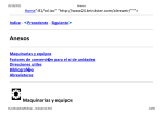
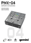
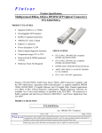
Operating Guide
Intended to alert the user to the presence of uninsulated “dangerous voltage” within the product’s
enclosure that may be of sufficient magnitude to constitute a risk of electric shock to persons.
Intended to alert the user of the presence of important operating and maintenance (servicing)
instructions in the literature accompanying the product.
CAUTION: Risk of electrical shock — DO NOT OPEN!
CAUTION: To reduce the risk of electric shock, do not remove cover. No user serviceable parts inside. Refer
servicing to qualified service personnel.
WARNING: To prevent electrical shock or fire hazard, do not expose this appliance to rain or moisture. Before
using this appliance, read the operating guide for further warnings.
Este símbolo tiene el propósito, de alertar al usuario de la presencia de “(voltaje) peligroso” sin aislamiento dentro de la caja del producto y que puede tener una magnitud suficiente como para constituir
riesgo de descarga eléctrica.
Este símbolo tiene el propósito de alertar al usario de la presencia de instruccones importantes sobre la
operación y mantenimiento en la información que viene con el producto.
PRECAUCION: Riesgo de descarga eléctrica ¡NO ABRIR!
PRECAUCION: Para disminuír el riesgo de descarga eléctrica, no abra la cubierta. No hay piezas útiles dentro.
Deje todo mantenimiento en manos del personal técnico cualificado.
ADVERTENCIA: Para evitar descargas eléctricas o peligro de incendio, no deje expuesto a la lluvia o humedad
este aparato Antes de usar este aparato, Iea más advertencias en la guía de operación.
Ce symbole est utilisé dans ce manuel pour indiquer à l’utilisateur la présence d’une tension dangereuse
pouvant être d’amplitude suffisante pour constituer un risque de choc électrique.
Ce symbole est utilisé dans ce manuel pour indiquer à l’utilisateur qu’il ou qu’elle trouvera d’importantes
instructions concernant l’utilisation et l’entretien de l’appareil dans le paragraphe signalé.
ATTENTION: Risques de choc électrique — NE PAS OUVRIR!
ATTENTION: Afin de réduire le risque de choc électrique, ne pas enlever le couvercle. Il ne se trouve à l’intérieur
aucune pièce pouvant être reparée par l’utilisateur. Confiez I’entretien et la réparation de l’appareil à un réparateur
Peavey agréé.
AVERTISSEMENT: Afin de prévenir les risques de décharge électrique ou de feu, n’exposez pas cet appareil à la
pluie ou à l’humidité. Avant d’utiliser cet appareil, lisez attentivement les avertissements supplémentaires de ce
manuel.
Dieses Symbol soll den Anwender vor unisolierten gefährlichen Spannungen innerhalb des Gehäuses
warnen, die von Ausreichender Stärke sind, um einen elektrischen Schlag verursachen zu können.
Dieses Symbol soll den Benutzer auf wichtige Instruktionen in der Bedienungsanleitung aufmerksam
machen, die Handhabung und Wartung des Produkts betreffen.
VORSICHT: Risiko — Elektrischer Schlag! Nicht öffnen!
VORSICHT: Um das Risiko eines elektrischen Schlages zu vermeiden, nicht die Abdeckung enfernen. Es befinden
sich keine Teile darin, die vom Anwender repariert werden könnten. Reparaturen nur von qualifiziertem
Fachpersonal durchführen lassen.
ACHTUNG: Um einen elektrischen Schlag oder Feuergefahr zu vermeiden, sollte dieses Gerät nicht dem Regen
oder Feuchtigkeit ausgesetzt werden. Vor Inbetriebnahme unbedingt die Bedienungsanleitung lesen.
2
ENGLISH
5150® II
Tube Guitar Amplifier
Congratulations on your purchase of the all new 5150® II. Peavey’s continuous design collaboration
with guitar icon and legend, Edward Van Halen, has produced yet another feature-packed, monster
guitar head. Like the original 5150 head, the 5150 II offers two channels. However, the 5150 II adds
separate EQ, Resonance, and Presence controls to each channel, giving you more control and
flexibility. The new footswitch provides foot control of channel selection, effects loop, and the newly
added ability to select the Crunch feature. Now you can instantly obtain that extra gain in the
Rhythm Channel with your foot and never have to take your hand off the guitar. Finally, the Clean
Channel has been added, completely redesigned to sound much cleaner, and has one 12AX7
devoted to just the Clean/Crunch.
The following guide explains these features and how to operate each one in order to obtain
your desired sound. We recommend that you read this manual carefully, paying close attention
to any warnings or cautions.
FEATURES:
• Two distinct tube channels with footswitch control
• LED “active” indicators for each channel
• Bright switch for Rhythm channel
• Crunch switch on Rhythm channel with footswitch control
• Separate equalizer sections for each channel
• Separate power amp controls (Resonance and Presence) for each channel
• Separate preamp controls (Pre and Post Gain) for each channel
• Standby power switch
• Bias test points on rear panel
• Effects loop with footswitch control
• 1/4" Preamp output jack
• Speaker impedance selection switch (4, 8, 16 ohm)
• Two parallel 1/4" speaker output jacks
• 120 watts output power ohm output power
• Metal three button footswitch with detachable 25' cable
5150® is a registered trademark of Edward Van Halen.
3
REAR PANEL FEATURES
2
1
3
10
7
8
9
6
4
5
POWER
(1)
LINE CORD:
This line cord provides the AC power to the unit. Connect the line cord to a properly
grounded AC supply. Damage to the equipment may occur if improper line voltage is used.
(See voltage marking on unit.) Never remove or cut the ground pin of the line cord plug.
NOTE: FOR UK ONLY
As the colors of the wires in the mains lead of this apparatus may not correspond with the
colored markings identifying the terminals in your plug, proceed as follows: (1) The wire which
is colored green and yellow must be connected to the terminal which is marked by the letter
E, or by the earth symbol, or colored green or green and yellow. (2) The wire which is colored
blue must be connected to the terminal which is marked with the letter N, or the color black.
(3) The wire which is colored brown must be connected to the terminal which is marked with
the letter L or the color red.
(2)
FUSE
WARNING: THE FUSE SHOULD ONLY BE REPLACED WHEN THE POWER CORD
HAS BEEN DISCONNECTED FROM ITS POWER SOURCE. A 5 amp fuse is located within
the cap of the fuse holder. It must be replaced with the same type and value in order to avoid
damage to the equipment and to prevent voiding the warranty. If the amp repeatedly blows
fuses, it should be taken to a qualified service center for repair.
(3)
GROUND SWITCH
This is a three-position, rocker type switch which, for most applications, should be operated in
the center (zero) position. If hum or noise is noticed coming from the speaker enclosure(s)
with the Ground Switch in the center position, place the Ground Switch to positive (+) or
negative (-) to minimize hum. Should a hum/noise problem continue, consult your authorized
Peavey dealer, the Peavey factory, or a qualified service technician.
NOTE: THE GROUND SWITCH IS NOT FUNCTIONAL ON 220/240 VOLT MODELS.
INs AND OUTs
(4)
SPEAKER JACKS
These jacks are provided for the connection of speaker enclosure(s). The minimum speaker
impedance is 4 ohms. The Impedance Selector Switch (5) should be set accordingly.
(5)
IMPEDANCE SELECTOR SWITCH (5)
Use this switch to select the appropriate impedance of the speaker enclosure(s) connected to
the Speaker Jacks (4). If two enclosures of equal impedance are used, the switch should be
set at one half of that value (e.g., two 16 ohm enclosures: set switch to 8 ohms; two 8 ohm
enclosures: set switch to 4 ohms).
4
(6)
REMOTE FOOTSWITCH JACK
This jack is provided for the connection of the supplied remote footswitch. The footswitch
cable should be plugged in before the amp is powered up. When the footswitch is plugged
into the Remote Footswitch Jack, the Channel Select switch (14) must be pressed to the “in”
position for remote selection of the Lead or Rhythm channel (right footswitch button). The On
and Off operation of Effects (left footswitch button) will work at all times. Remote selection of
Crunch gain boost (center footswitch button) is available only when the Crunch Switch (22) is
selected. See page 9 for detailed Footswitch diagram.
(7/8) EFFECTS SEND/EFFECTS RETURN
Signals are supplied to outboard effects or signal processing units by patching from the
Effects Send (7) output into the outboard unit(s) and back into the Effects Return (8) input
using shielded cables with 1/4" mono phone plugs. Only non-gain effects devices (chorus,
reverb, delay, etc.) should be used in the effects loop. If footswitch is used, “Effects” must be
selected (LED illuminated) for effects to work.
(9)
PREAMP OUT
This output can be used to send a preamp signal from the 5150 II to a mixing console, tape
recorder, etc., using a shielded instrument cable. Patching from the PREAMP OUT does not
affect the normal operation of the amplifier.
BIAS ADJUST SYSTEM
(10)
BIAS TEST TERMINALS
These terminals, along with the adjustment knob behind the grill are provided to measure
and adjust the power amp tubes’ bias. The bias adjustment should only be done by a
qualified technician.
FRONT PANEL FEATURES
13
15
14
21
16
22
15
20
12
17
18
19
23
11
24
ON STANDBY
(11)
POWER SWITCH/LED
This switch supplies power to the unit. Depressed to the “ON” position, the red Power LED
indicator will illuminate above the Power Switch when power is being supplied to the unit.
(12)
STANDBY SWITCH/LED
This switch allows the 5150 II to be placed in a non-operational standby mode. When the
Standby Switch is activated, the tubes remain hot and ready for instantaneous operation,
eliminating warm-up time. The Standby LED indicator above the switch will illuminate when
the amp is in the operational mode.
5
PREAMP
(13)
INPUT
The 5150 II input jack is designed to accommodate a variety of guitar output levels,
regardless of pickup configuration. Due to the extreme high gain capabilities of the 5150 II, it
is imperative that you use a premium shielded instrument cable in order to minimize noise.
(14)
CHANNEL SELECT SWITCH
This switch allows selection of the Rhythm or Lead Channel. Depressing the switch to the “in”
position activates the Lead Channel. The red LED next to the Lead Pre control will illuminate
to indicate that the Lead Channel is active. In the “out” position, the Rhythm channel is
activated and the green LED illuminates next to the Rhythm Pre control to indicate that the
Rhythm Channel is active. Channels may be remotely selected using the 5150 II’s footswitch.
If remote selection is desired, the Channel Select Switch must be set to the “in” position
(Lead Channel). See page 9.
(15)
CHANNEL SELECT LED
Both the Rhythm Channel and Lead Channel have these LEDs to indicate which channel is
active. The two Channel Select LEDs are never on at the same time. The channel with its
indicator illuminated is the active channel.
(16/20) PRE and POST GAIN
The channel Pre (16) and Post (20) Gain controls operate in the same manner for both
channels. However, the Lead channel does have more pregain than the Rhythm Channel. In
most applications, the Rhythm channel should be set up with the Pre Gain at the lower
“cleaner” settings (0-4) and the Post Gain should be set for overall volume. The Rhythm
channel can be converted to a medium distortion channel by activating the Crunch switch
(22). This will more closely match the pre gain of the two channels. The Lead channel should
be set up with the Pre Gain at the mid to upper settings (5-10) and the Post Gain should be
set for overall volume.
(17/18/19) EQUALIZATION
The 5150 II’s equalization block features passive low, mid, and high EQ that is custom
tailored for each channel to Edward Van Halen’s specifications. Adjusting the control(s)
counterclockwise will result in an attenuation of the signal within the frequency band.
(21)
BRIGHT SWITCH
Activates a preset boost in the treble frequencies (6 dB at 2 kHz) and affects only the Rhythm
Channel.
(22)
CRUNCH SELECT SWITCH
Boosts the gain of the Rhythm channel to create a medium distortion or in between tone.
Depress to the “in” position to activate.
(23/24) RESONANCE / PRESENCE
Unique to Peavey instrument amplifiers, the Resonance control (23) can be set to boost the
gain of the power amp in the low frequencies at the resonance/attenuation point of the
speaker cabinet. In simple terms, the Resonance control works like a low EQ to offset lowend frequency drop out. The Presence control (24) works in the same manner, boosting the
high frequencies. Experimentation using your particular speaker cabinet, along with personal
taste, will determine your setting for these important controls.
6
5150® II
SPECIFICATIONS
PREAMP SECTION
POWER AMPLIFICATION
SECTION
EFFECTS RETURN:
Impedance: Very High Z, 470 k ohms
Designed Level: -10 dBV, 300 mV RMS
The following specs are measured @
1 kHz with the controls preset as follows:
Low and High EQ @ 10
Mid EQ @ 0
Bright out
Lead and Rhythm Posts @ 10
Presence and Resonance @ 0 dB
Nominal levels with Pre Gains @ 5
Minimum levels with Pre Gains @ 10
RATED POWER AND LOAD:
120 W RMS into 16, 8, or 4 ohms
POWER @ CLIPPING:
(Typically @ 5% THD, 1 kHz, 120 V AC
line)
130 W RMS into 16, 8, or 4 ohms
(Bias must be reduced to measure.)
PREAMP OUT:
Load Impedance: 47 k ohms or greater
Nominal Output: +10 dBV, 3 V RMS
REMOTE FOOTSWITCH:
Special 3-button unit with LED indicators
(supplied)
Channel select and reverb
PREAMP INPUT:
FREQUENCY RESPONSE:
Impedance: Very high Z, 470K ohms
+0, -3 dB, 50 Hz to 20 kHz @ 100 W
RMS into 8 ohms
SYSTEM HUM AND NOISE @
NOMINAL LEVEL (clean channel):
Lead Channel (with channel select in):
Nominal Input Level: -60 dBV,
1 mV RMS
Minimum Input Level: -76 dBV,
.15 mV RMS
HUM AND NOISE:
Greater than 75 dB below rated power
POWER AMP EQ:
Active Presence: +10 dB @ 2 kHz
Active Resonance: +10 dB @ cabinet
resonant frequency
(20 Hz to 20 kHz unweighted)
Greater than 63 dB below rated power
EQUALIZATION:
Custom Low, Mid, and High passive type EQ
Push Bright (Rhythm Channel only)
+6 dB @ 2 kHz
Push Crunch (Rhythm Channel only)
Increases gain
Clean Channel (with channel select out):
Nominal Input Level: -30 dBV,
30 mV RMS
Minimum Input Level: -34 dBV,
20 mV RMS
Maximum Input Level: 0 dBV,
1.0 V RMS
(Subtract 24 dB with Crunch switch in.)
POWER CONSUMPTION (Domestic):
400 watts 50/60 Hz, 120 V AC
(Domestic)
TUBE COMPLEMENT:
6-12AX7 preamp tubes
(1 for clean/crunch, 3 for Lead, 1 for
EFX and 1 phase splitter
4-6L6GC
DIMENSIONS (H x W x D):
10" x 26.625" x 11.75"
(25.4 cm x 67.6 cm x 29.8 cm
WEIGHT:
EFFECTS SEND:
48.3 lbs. (21.91 kg)
Load Impedance: 47 k ohms or greater
Nominal Output: -10 dBV, 300 mV RMS
Features and specifications subject to change without notice.
5150® II
BLOCK DIAGRAM
PRE
LOW MID HI
POST
TUBE STAGES
LEAD
FOOTSWITCH
EFFECTS
TUBE STAGE
SWITCH
LOGIC
SEND
SWITCH
LOGIC
FOOTSWITCH
INPUT
TUBE BUFFER
RETURN
CHANNEL
SELECT
TUBE STAGES
TUBE STAGES
RHYTHM
PRE
LOW MID HI
PUSH
BRIGHT
SPEAKER
OUTPUTS
POST
PUSH
CRUNCH
TUBE
POWER
AMP
IMPEDANCE
SWITCH
FOOTSWITCH
SWITCH
LOGIC
PREAMP
OUT
SIGNAL FLOW BLOCK DIAGRAM
RESONANCE PRESENCE
LEAD
7
RESONANCE PRESENCE
RHYTHM
5150® II
HOOKUP DIAGRAM
16 Ohms
8 Ohms
Set switch
to 8 Ohms
Set switch
to 4 Ohms
16 Ohms
8 Ohms
DeltaFex™ Rack Mount Effects Unit
From EVH® 5150 II Effects
Send Output to Input of
Rack Effects Unit
EVH® 5150 II Back Panel
From Output of Rack
Effects Unit to EVH® 5150 II
Effects Return Input
Delta Stomp™ Floor Pedal
From EVH® 5150 II Effects
Send Output to Input of
Effects Pedal
From Output of Effects Pedal
to EVH® 5150 II Effects
Return Input
EVH® 5150 II Back Panel
8
5150® II
RECOMMENDED SETTINGS
Southern Rock/Country
In
In
Set to proper volume
Out
Signature Setting
In
In
In
Set to proper volume
Activates
Effects Loop
when switch
is pressed
and LED
illuminates
Activates
Crunch Voicing
on Rhythm
when switch
is pressed
and LED
illuminates
*Selects
(toggles)
between
Rhythm
and
Lead
channels
All switches are push on/push off.
There are no momentary switches on the footswitch.
*NOTE:
Channel select switch (14) must be pressed
to the “in” position for this switch to function.
9
ESPAÑOL
Amplificador de bulbos para guitarra
5150® II
Felicidades por tu compra del nuevo 5150® II. La colaboraci≤n cont¿nua de Peavey con el ¿dolo y
leyenda de la guitarra, Edward VanHalen, ha producido un monstruoso cerebro para guitarra lleno
de nuevas ventajas Como el cerebro 5150 original, el 5150 II ofrece dos canales. Sin embargo, el
5150 II a±ade controles de Ecualizaci≤n Separada, Resonancia, y Presencia a cada canal, dßndote
mayor control y flexibilidad. El nuevo pedal ofrece control de pie de canales, “loop” de efectos, y la
nuva abilidad de seleccionar la funci≤n de “crunch”. Ahora puedes obtener esa ganancia adicional
en el canal de Ritmo con el pie, sin tener que quitar las manos de la guitarra nunca mßs.
Finalmente, el canal limpio ha sido a±adido, redise±ado completamente para sonar mucho mßs
limpio, y tiene un 12AX7 dedicado exclusivamente al limpio/crunch.
La siguiente gu¿a explica estas caracter¿sticas y c≤mo operar cad una para lograr obtener tu
sonido deseado. Te recomendamos leer el manual cuidadosamente, poniendo atenci≤n a las
precauciones y avisos.
CARACTER¿STCAS:
•
•
•
•
•
•
•
•
•
•
•
•
•
•
•
Dos canales distintivos con control de pedal
Indicadores LED “activos” para cada canal
Switch de brillantez para el canal de Ritmo (o acompa±amiento)
Switch de crunch en el canal de Ritmo con control de pedal
Secciones separadas de ecualizador para cada canal
Controles de amplificador de poder (Resonancia y Poder) para cada canal
Controles separados de preamp (Pre y Post Ganacia) pra cada canal
Switch de poder “standby”
Puntos de prueba de biaas en el panel trasero
Loop de efectos con control de pedal
Salida de Preamp de 1/4"
Switch de selecci≤n de impedancia para las bocinas (4, 6, 8 ohmios)
Dos salidas paralelas de 1/4" para bocina
Salida de 120 wats de salida de poder en ohmios
Pedal de tres botones con cable removible de 25'
5150® es una marca registrada de Edward Van Halen
10
CARACTER¿STICAS DEL PANEL TRASERO
2
1
3
10
7
8
9
6
4
5
PODER
(1)
CABLE DE L¿NEA:
Est cable de linea provee el poder de CA a la unidad. Conecta el cable a un suministro de
CA propiamente aterrizado. Da±o al equipo puede causarse si se usa un voltage de linea
inapropiado. (Ver marcaci≤n de voltage en la unidad). Nunca quites el alfiler de tierra del
conector del cable de l¿nea.
NOTA S¿LO PARA EL REINO UNIDO
Ya que el color de los cables de este aparato pueden no corresponder a las marcas de
colores que identidfican las terminales en tu conector, haz lo siguiente: (1) El alambre verde y
amarillo debe de conectarse a la terminal marcada con la letra E, o por el s¿mbolo de tierra,
o del color verde o verde y amarillo. (2) El alambre azul debe ser conectado a la terminal
marcada con la letra N , o de color negro. (3) El alambre caf¿ debe conectarse a la terminal
marcada con la letra L o el color rojo.
(2)
FUSIBLE
PRECAUCI¿N: EL FUSIBLE SOLAMENTE DEBE SER REEMPLAZADO CUANDO EL
CABLE DE PODER HAY ASIDO DESCONECTADO DE SU FUENTE DE PODER. Un fusible
ha sido colocado dentro de la tapa del compartimiento del fusible. Debe ser reemplazado con
uno del mismo valor y tipo para evitar alg·n da±o al equipo y para no cancelar la garant¿a. Si
el amplificador quema fusibles cont¿nuamente, debe ser llevado a un centro de servicio cali
ficado para ser reparado.
(3)
SWITCH DE TIERRA
Este es un switch de tres posiciones que, para la mayor¿a de las aplicaciones, se debe
operar en la posici≤n central (cero). Si un zumbido o ruido saliera de la(s) bocina(s) con el
Switch de Tierra en la posici≤n central, pasa el switch a la posici≤n (+) ≤ (-) para minimizar el
zumbido. Si persiste este problema, consulta a un vendedor autorizado de Peavey, a la
fßbrica misma, o a un t¿cnico de servicio calificado.
NOTA: EL SWITCH DE TIERRA NO FUNCIONA EN LOS MODELOS DE 220/240 VOLTIOS.
ENTRADAS Y SALIDAS
(4)
CONEXIONES PARA BOCINAS
Estas conexiones sirven para conectar bocina a 5150 II. La m¿nima impedancia es 4
ohmios. El Switch Selector de Impedancia (5) debe ser ajustado de manera correspondiente.
(5)
SWITCH DE SELECTOR DE IMPEDANCIA
Usa este switch para seleccionar la impedancia apropiada de la bocina o bocinas conectada
a las conexiones para bocinas (4). Si dos gabinetes con la misma impedancia son usados, el
11
switch debe ser ajustado a la mitad de ese valor, por ejemplo: dos gabinetes de 16 ohmios:
ajustar switch a 8 ohmios; dos gabinets de 8 ohmios: ajustar switch a 4 ohmios.
(6)
ENTRADA PARA PEDAL REMOTO
Este pedal se proporciona para para la conexi≤n del pedal remoto inclu¿do. El cable del
pedal debe ser conectado antes de que se prenda el ampli. Cuando es conectado el pedal
su entrada, el Switch de Selecci≤n de Canal (14) se debe presionar para quedar oprimido
para la selecci≤n remota del canal “Lead” o “Rhythm” (bot≤n derecho del pedal). La operci≤n
de Encendido y Apagado de Efectos (bot≤n izquirdo del pedal) funcionarß en todo momento.
La selecci≤n de la ganancia de “Crunch” (bot≤n central del pedal) s≤lo estß disponible
cuando est¿ seleccionado el Switch de Crunch (22). Ver la pßgina 9 para un diagrama
detallado del pedal.
(7/8) ENV¿O Y RETORNO DE EFECTOS
La se±ales son enviadas a unidades perif¿ricas de efectos al parchear la salida de Env¿o de
Efectos (7) a las unidades perif¿ricas y de regreso a la entrada del Retorno de Efectos (8)
usando cables blindados monof≤nicos con conectores de 1/4". S≤lo efectos sin ganancia
(chorus, reverb, delay, etc.) deben ser usados en el “loop”. Si se usa el pedal, debe
seleccionarse “Effects” (led iluminado) para que los efectos funcionen.
(9)
SALIDA DE PREAMP
Esta salida puede ser usada para mandar una se±al de preamp del 5150 II a una consola,
grabadora, etc., usando un cable brindado de instrumento. El parchear desde la SALIDA DE
PREAMP no afecta la operaci≤n normal del amplificador.
SISTEMA DE AJUSTE DE BIAS
(10)
TERMINALES DE PRUEBA DE BIAS
Estas terminales, junto con la perilla de ajuste que se encuentra detrßs de la parrilla sirven
para medir y ajustar el bias de los bulbos del amplificador de poder. El ajuste del bias s≤lo
debe ser llevado a cabo por un t¿cnico calificado.
CARACTER¿STICAS DEL PANEL FRONTAL
13
15
14
21
16
22
15
20
12
17
18
19
23
11
24
ON STANDBY
(11)
SWITCH/LED DE PODER
Este switch le da poder a la unidad. Oprimido en la posici≤n “on”, el LED rojo de Poder se
iluminarß arriba del Switch de Poder cuando la unidad sea suministrada con poder.
(12)
SWITCH/LED “STANDBY”
Este switch permite que el 5150 II se coloque en un modo no operacional. Cuando se activa
el switch de stanby, los bulbos permanecen calientes y listos para una operaci≤n
12
instantßnea, eliminando el tiempo de calientamiento. El indicador led de Standby arriba del
switch se iluminarß cuando el ampli est¿ en modo operacional.
PREAMPLIFICADOR
(13)
ENTRADA
La entrada del 5150 II estß dise±ada para recibir una variedad de niveles de salida de
guitarras, sin importar la configuraci≤n de las pastillas. Debido a la capacidad de ganancias
extremadamente altas del 5150 II es imperativo que uses un cable blindado de instrumento
de la mßs alta calidad para minimizar el ruido.
(14)
SWITCH DE SELECCI¿N DE CANAL
Este switch permite la selecci≤n de los canales de acompa±amiento o l¿der. El switch en la
posici≤ oprimida activa el canal l¿der. El LED rojo que estß junto al control “Lead Pre” se
iluminarß para indicar que el canal l¿der estß activo. En la posici≤n no oprimida, el canal de
acompa±amiento (rhythm) es activado y el LED verde se iluminarß junto al control “Rhythm
Pre” para indicar su activaci≤n. Los canales pueden ser activados remotamente usando el
pedal del 5150 II. Si se desea esta secci≤n remota, el Switch de Selecci≤n de Canal debe
estar en la posici≤n oprimida (canal L¿der). Ver pßgina 9.
(15)
LED DE SELECCI¿N DE CANAL
Tanto el canal de acompa±amiento com el l¿der, tienen estos LEDs para indicar qu¿ canal
estß activo. Estos dos LEDs nunca estßn prendidos al mismo tiempo.
(16/20) GANANCIA PRE Y POST
Los controles de ganancia de los canales Pre (16) y Post (20) operan de la misma manera
para ambos canales. Sin embargo, el canal l¿der s¿ tiene mßs pre ganancia que el canal de
acompa±amiento. En la mayor¿a de las aplicaciones el canal de acompa±amiento debe de
ajustarse con la pre ganancia a los valores mßs “limpios” (0-4) y la post ganancia debe ser
ajustada para un volumen general. El canal de acomap±amiento puede ser convertido a una
distorsi≤n mediana activando el switch Crunch (22). Esto igualarß mßs de cerca la pre
ganancia de los dos canales. El canal l¿der debe ser ajustado con la pre ganancia en los
valores medios a altos (5-10) y la post ganancia debe ser ajustada para un volumen general.
(17/18/19) ECUALIZACI¿N
El bloque de ecualizaci≤n del 5150 II presenta ecualizaci≤n de bajas medias y altas
frecuancias que estß dise±ado espec¿ficamente para cada canal por Edward Van Halen. Si
ajustas los controles en direcci≤n contraria a las manecillas del reloj, atenuarßs la
se±aldentro de la banda de frecuencia.
(21)
SWITCH DE BRILLANTEZ
Activa un aumento predeterminado en las frecuancias agudas (6 dB a 2 kHz) y afecta s≤lo al
canal de acompa±amiento.
(22)
SWITCH DE SELECCI¿N DE CRUNCH
Aumenta la ganancia del canal de acompa±amiento para crear una distorsi≤n media. Debe
estar en la posici≤n oprimida para activarla.
(23/24)RESONANCIA/PRESENCIA
El control de resonancia (23) s≤lo se encuentra en los apmlificadores de instrumento de
13
Peavey. ¿ste se puede ajustar para aumentar la ganancia del amplificador de poder en las
frecuencias bajas del punto de resonancia/atenuaci≤n del gabinete de bocina. En t¿rminos
mßs sencillos, el control de resonancia funciona como un ecualizador de bajas frecuencias
para evitar la p¿rdida de las mismas. El control de presencia (24) funciona de la misma
manera, aumentando las frecuencias altas. La experimentaci≤n al usar tu propia bocina,
aunada al gusto personal, determinarß tus valores para estos importantes controles.
5150« II
ESPECIFICACIONES
SECCI¿N DE AMPLIFICACI¿N DE PODER
PODER Y CARGA CLASIFICADOS:
120 W RMS a 16, 8, ≤ 4 ohmios
PODER @ SATURACI¿N:
(T¿picamente @ 5% THD, 1 kHz, 120 V linea CA)
130 W RMS a16, 8, o 4 ohmios
(Bias debe reducirse a la medida.)
RESPUESTA DE FRECUENCIA :
+0, -3 dB, 50 Hz a 20 kHz @ 100 W RMS a 8 ohmios
ZUMBIDO Y RUIDO:
Mßs que 75 dB menos que el poder clasificado
Canal l¿der (con selector de canal oprimido):
Nivel nominal de entrada : -60 dBV, 1 mV RMS
Nivel m¿nimo de entrada: -76 dBV, 15 mV RMS
Clean Channel (with channel select out):
Canal limpio : -30 dBV, 30 mV RMS
Nivel m¿nimo de entrada: -34 dBV, 20 mV RMS
Nivel mßximo de entrada: 0 dBV, 1.0 V RMS
(Restar 24 dB con Crunch activado)
ENV¿O DE EFECTOS:
Impedancia de carga: 47 k ohmios o mayor
Salida Nominal: -10 dBV, 300 mV RMS
RETORNO DE EFECTOS:
Impedancia: Z Muy Alta, 470 k ohmios
Nivel Dise±ado: -10 dBV, 300 mV RMS
ECUALIZADOR DEL AMPLI DE PODER:
Presencia activa: +10 dB @ 2 kHz
Presencia activa: +10 dB @ gabinete
frecuencia resonante
CONSUMO DE PODER (Dom¿stico):
400 watts 50/60 Hz, 120 V CA
(Dom¿stico)
SALIDA DE PREAMP :
Impedancia de carga: 47 k ohmios o mayor
Salida Nominal: +10 dBV, 3 V RMS
PEDAL REMOTO :
Unit especial de tres votones con indicadores LED (inclu¿do)
Selecci≤n de canal y reverb
Complemento de bulbos:
6-12AX7 bulbos de preamp
(1 para limpio/crunch, 3 para l¿der, 1 para EFX y 1 “splitter” de
fase
4-6L6GC
SECCI¿N DE PREAMPLI
Las especificaciones siguientes se miden @ 1 kHz con los
controles ajustados a los siguientes valores:
EQ de altas y bajas @ 10
EQ de Med @ 0
Brillo fuera
Postes de l¿der y acomp.@ 10
Presencia y Resonancia @ 0 dB
Niveles nominales con Pre Ganancias@ 5
Niveles m¿nimos con Pre Ganancias @ 10
RUIDO Y ZUMBIDO DE SISTEMA@
NIVEL NOMINAL (canal limpio):
(20 Hz a 20 kHz sin peso)
Mßs de 63 dB bajo el poder clasificado
EQUALIZACI¿N:
EQ Especial de bajas, medias y altas
Bright Activado (S≤lo canal de acomp.) +6 dB @ 2 kHz
Crunch Activado (S≤lo canal de l¿der) Aumenta la ganancia
DIMENSIONES :
10" x 26.625" x 11.75"
(25.4 cm x 67.6 cm x 29.8 cm)
PESO:
48.3 lbs. (21.91 kg)
ENTRADA DE PREAMP
Impedancia: Z muy alta , 470K ohmios
Features and specifications subject to change without notice.
14
FRANÇAIS
5150® II
Amplificateur à lampes pour guitare
Nous vous félicitons pour l’achat du 5150® II. Il représente le fruit d’une collaboration entre Peavey
et Edward Van Halen. De même que le 5150 original, le 5150 II possède 2 canaux. Cependant,
chacun dispose à présent de son équaliseur et de ses réglages de présence et résonance pour un
contrôle et une flexibilité accrus. Le nouveau pédalier inclu vous donne accés aux deux canaux, à la
fonction Crunch du canal Rythm et permet d’engager la boucle d’effet. Vous avez donc à présent 3
sons différents accessibles au pied. Par ailleurs, le canal Rythm a été repensé pour vous donner
accés à plus de sons clairs.
Ce manuel décrit toutes les fonctions et possibilités du 5150 II. Nous vous recommandons de le lire
attentivement et de respecter toutes les précautions d’emploi mentionnées.
CARACTERISTIQUES:
• Deux canaux séparés accessibles au pédalier
• LED sur chaque canal
• Sélecteur Bright sur le canal Rhythm
• Sélecteur Crunch sur le canal Rhythm (fonction accessible au pédalier)
• Equalisation séparée sur chaque canal
• Contrôles d’ampli de puissance séparés (Résonance et Présence) pour chaque canal
• Points de mesure du bias des lampes de sortie en face arrière
• Boucle d’effets contrôlée au pédalier
• Sortie préampli
• Sélecteur d’impédance 4, 8 ou 16 Ohm
• Deux sorties HP Jacks
• 120 Watt
• Pédalier métallique avec câble détachable
15
FACE ARRIERE
2
1
3
10
7
8
9
6
4
5
ALIMENTATION
(1)
CONNECTEUR D’ALIMENTATION IEC:
Connecteur IEC permettant l’alimentation du 5150 II. L’utilisation d’une ligne secteur d’une
tension inappropriée peut causer des dommages à votre appareil (consultez les tensions
d’alimentation inscrites sur l’appareil). Assurez-vous que l’amplificateur est toujours
correctement connecté à la terre.
(2)
FUSIBLE
Un fusible de 3A est placé dans le capuchon du porte-fusible. Si le fusible saute, débranchez
l’appareil et mettez l’interrupteur d’alimentation en position “0ff”; remplacez le fusible avec un
fusible du même type uniquement. Fermez correctement le porte-fusible et reconnectez
l’appareil à l’alimentation secteur. L’ampli étant en standby et le contrôle de volume au
minimum, basculez l’interrupteur en position “On”. Si le fusible saute, débranchez l’appareil et
faîtes-le inspecter par un technicien qualifié.
(3)
GROUND SWITCH
Cet interrupteur est absent sur les versions 220/240V
ENTREES ET SORTIES
(4)
SORTIES HAUT-PARLEURS
Ces sorties parallèles sont destinées à la connexion de vos enceintes. L’impédance totale
minimum des haut-parleurs est de 4 Ohm. La position du sélecteur d’impédance doit
correspondre à l’impédance totale des enceintes. Il est par ailleurs impératif d’utiliser du câble
pour haut-parleur pour la connexion aux enceintes.
(5)
SELECTEUR D’IMPEDANCE
Utilisez ce sélecteur pour faire correpondre l’impédance de sortie de l’amplificateur à celle
des enceintes connectées aux sorties HP(4). Si deux enceintes de même impédance sont
connectées, sélectionnez la moitié de cette valeur (par exemple: avec deux enceintes de 16
Ohm, sélectionnez 8 Ohm; avec deux enceintes de 8 Ohm, sélectionnez 4 Ohm).
(6)
PRISE DE PEDALIER
Cette prise est destinée à connecter le pédalier inclu avec le 5150 II. Lors de l’utilisation du
pédalier, le sélecteur de canal (14) doit être enfoncé de même que le sélecteur Crunch (22)
pour que ces fonctions puissent être utilisées. La commande de la boucle d’effets au pédalier
sera toujours effective.
(7/8) EFFECTS SEND/EFFECTS RETURN
Ces connexions constituent les entrée et sortie de la boucle d’effets de l’amplificateur
connectez la sortie Effects Send (7) à l’entrée de votre processeur d’effets et l’entrée Effects
16
Return (8) à sa sortie en utilisant des câbles blindés de bonne qualité. Placez dans la boucle
d’effets les effets de modulation (chorus, flanger, vibrato, etc...) et d’espace (réverbes, delays,
etc...).
(9)
SORTIE PREAMP OUT
Cette sortie peut être utilisée pour connecter le préampli du 5150 II à un ampli de puissance
supplémentaire, une table de mixage, etc. L’utilisation de cette sortie n’affecte pas le
fonctionnement de l’amplificateur.
REGLAGE DU BIAS
(10)
POINTS DE MESURE DU BIAS
Ces points de mesure permettent le réglage du bias des lampes de sortie (réglage placé
derrière la grille de protection arrière). Ce réglage doit impérativement être effectué par un
professionnel. Un réglage mal effectué peut causer la destruction des lampes ou du
transformateur de sortie.
FACE AVANT
13
15
14
21
16
22
15
20
12
17
18
19
23
11
24
(11)
INTERRUPTEUR D’ALIMENTATION
Cette interrupteur met l’amplificateur sous tension. En position On, la LED rouge
d’alimentation s’allume pour indiquer que l’appareil est sous tension.
(12)
STANDBY
Cet interrupteur permet de mettre le 5150 II en mode d’attente. En Standby, les lampes du
5150 II reste chauffées mais ne reçoivent pas la haute tension d’alimentation. Mettez
l’appareil en Standby lorsqu’il n’est pas utilisé ou avant de mettre l’amplificateur en marche.
Le 5150 II doit rester en standby plusieurs minutes aprés la mise sous tension pour que les
lampes atteignent leur température de fonctionnement. Ceci permet de rallonger
considérablement leur durée de vie et prévient la destruction prématurée du fusible.
PREAMPLI
(13)
ENTREE
L’entrée du 5150 II accepte tout type de niveau de signaux de guitare, quelques soient les
micros utilisés. Etant donné le gain particulièrement élevé du 5150 II, il est impératif d’utiliser
des câbles blindés de haute qualité pour toutes les connexions.
(14)
SELECTEUR DE CANAL
Ce sélecteur permet de passer du canal Rythm au canal Lead. En position enfoncée, le canal
Lead est sélectioné et la LED rouge située à côté du contrôle pré gain de ce canal
s’allumera. En position ressortie, le canal Rythm est activé et la LED verte de ce canal
s’allumera. Il est possible de changer de canal depuis le pédalier du 5150 II. Pour cela, le
sélecteur de canal doit être en position enfoncée (position pour le canal Lead).
17
(15)
LED DE CANAL
Chaque canal possède sa propre LED pour indiquer son activité.
(16/20) PRE et POST GAIN
Les contrôles Pre (16) et Post (20) Gain fonctionnent selon le même principe pour les deux
canaux. Le réglage Pre gain détermine le niveau de distortion et le réglage Post gain permet
de déterminer le volume général du canal. Le canal Rhythm est capable d’offrir toute une
gamme de sons clairs ou légèrement saturés en utilisant la fonction Crunch (22).
(17/18/19) EQUALISATION
Le 5150 II posède une équalisation 3 bandes par canal. Les contrôles de graves, médiums et
aigus ont été conçus selon les spécifications d’Edward Van Halen et possèdent une action
différente sur les deux canaux.
(21)
SELECTEUR BRIGHT
Ce sélecteur active un boost de fréquences aigües sur le canal Rythm (6 dB à 2 kHz).
(22)
SELECTEUR CRUNCH
Cet interrupteur augmente le gain du canal Rhythm pour obtenir un son plus saturé. Cette
fonction est accessible au pédalier (l’interrupteur doit être en position enfoncée).
(23/24) RESONANCE / PRESENCE
Le contrôle de Résonance (23), exclusif aux amplificateurs Peavey, agit tel un contrôle de
présence pour les basses fréquences. Il permet d’augmenter la réponse de l’amplificateur
dans les basses fréquences. Le contrôle de Présence (24) ajuste la réponse de l’étage de
puissance dans les hautes fréquences. En plus de leur aide au sculptage de votre son, les
contrôles permettent de corriger la réponse de l’amplificateur en fonction de la salle dans
laquelle il est utilisé (salle sourde ou trop brillante, etc...).
18
POWER AMPLIFICATION
SECTION
RATED POWER AND LOAD:
120 W RMS into 16, 8, or 4 ohms
POWER @ CLIPPING:
(Typically @ 5% THD, 1 kHz, 120 V AC
line)
130 W RMS into 16, 8, or 4 ohms
(Bias must be reduced to measure.)
5150® II
SPECIFICATIONS
PREAMP SECTION
The following specs are measured @
1 kHz with the controls preset as follows:
Low and High EQ @ 10
Mid EQ @ 0
Bright out
Lead and Rhythm Posts @ 10
Presence and Resonance @ 0 dB
Nominal levels with Pre Gains @ 5
Minimum levels with Pre Gains @ 10
PREAMP INPUT:
FREQUENCY RESPONSE:
+0, -3 dB, 50 Hz to 20 kHz @ 100 W
RMS into 8 ohms
HUM AND NOISE:
Greater than 75 dB below rated power
POWER AMP EQ:
Active Presence: +10 dB @ 2 kHz
Active Resonance: +10 dB @ cabinet
resonant frequency
POWER CONSUMPTION (Domestic):
400 watts 50/60 Hz, 120 V AC
(Domestic)
TUBE COMPLEMENT:
6-12AX7 preamp tubes
(1 for clean/crunch, 3 for Lead, 1 for
EFX and 1 phase splitter
4-6L6GC
Impedance: Very high Z, 470K ohms
Lead Channel (with channel select in):
Nominal Input Level: -60 dBV,
1 mV RMS
Minimum Input Level: -76 dBV,
.15 mV RMS
Clean Channel (with channel select out):
Nominal Input Level: -30 dBV,
30 mV RMS
Minimum Input Level: -34 dBV,
20 mV RMS
Maximum Input Level: 0 dBV,
1.0 V RMS
(Subtract 24 dB with Crunch switch in.)
EFFECTS SEND:
Load Impedance: 47 k ohms or greater
Nominal Output: -10 dBV, 300 mV RMS
EFFECTS RETURN:
Impedance: Very High Z, 470 k ohms
Designed Level: -10 dBV, 300 mV RMS
PREAMP OUT:
Load Impedance: 47 k ohms or greater
Nominal Output: +10 dBV, 3 V RMS
REMOTE FOOTSWITCH:
Special 3-button unit with LED indicators
(supplied)
Channel select and reverb
SYSTEM HUM AND NOISE @
NOMINAL LEVEL (clean channel):
(20 Hz to 20 kHz unweighted)
Greater than 63 dB below rated power
EQUALIZATION:
Custom Low, Mid, and High passive type EQ
Push Bright (Rhythm Channel only)
+6 dB @ 2 kHz
Push Crunch (Rhythm Channel only)
Increases gain
DIMENSIONS (H x W x D):
10" x 26.625" x 11.75"
(25.4 cm x 67.6 cm x 29.8 cm
WEIGHT:
48.3 lbs. (21.91 kg)
Features and specifications subject to change without notice.
19
DEUTSCH
5150® II
Röhrenverstärker
Herzlichen Glückwunsch zum Kauf des neuen 5150® II. Dieser Amp ist die Fortsetzung des
bekannten Röhrentopteils aus der Zusammenarbeit zwischen Edward van Halen und Peavey.
Genau wie das Vorgängermodell besitzt dieser Amp über 2 Kanäle, die bei diesem neuen Modell
allerdings über je einen eigenen EQ sowie Resonanz- und Presence-Regler verfügen. Mit dem
Fußschalter wird zwischen den Kanälen hin- und hergeschaltet, der Effekt-Loop eingeschaltet und
die Crunch-Features eingestellt. Ab jetzt kannst Du also sofort mehr Gain auf den Rhytmus-Kanal
legen ohne die Hände von der Gitarre nehmen zu müssen. Zu guter Letzt wurde der Clean-Kanal
gründlich überarbeitet und bietet nun einen viel klareren Sound durch die zusätzlich eingebaute
12AX7 Röhre für den Clean/Crunch Sound.
Wir werden Dir in diesem Heft erklären, wofür die ganzen Regler und Buchsen sind. Bitte lies´ auch
die Warnhinweise, die nicht nur zu unserem Vergnügen, sondern auch speziell für Deine Gesundheit
angefügt wurden.
NA, WAS HAT ER DENN?
•
•
•
•
•
•
•
•
•
•
•
•
•
•
•
Zwei getrennte Kanäle, über Fußschalter wählbar
LED Anzeige “Active” pro Kanal
Bright Schalter für den Rhythmus-Kanal
Crunch Schalter am Rhythmus-Kanal, über Fußschalter wählbar
Je Kanal ein EQ
Getrennt voneinander einstellbare Amp Regelung (Resonanz und Presence) pro Kanal
Getrennt voneinander einstellbare Preamp Regelung (Pre und Post Gain) pro Kanal
Standby Schaltung
Bias Test Points auf der Rückseite des Gerätes
Effekt Loop, über den Fußschalter wählbar
6.3mm Preamp Out Klinkenbuchse
Impedanzwahlschalter für die anzuschließenden Lautsprecher (4, 8, 16 Ohm)
Zwei 6.3mm Output-Buchsen (parallel)
120 “mörderische” Röhrenwatt
Fußschalter (drei Schalter, ca. 8,5 m Kabel)
20
RÜCKSEITE DES GERÄTES
2
1
3
10
7
8
9
6
4
5
NETZANSCHLUß
(1)
NETZKABEL:
Irgendwoher muß der Strom ja kommen. Bitte NICHT die Erdung aus irgendeinem
unerfindlichen Grund isolieren.... und bitte VORHER feststellen, ob die Stromversorgung mit
den Angaben am Gerät übereinstimmt.
(2)
SICHERUNG
WARNUNG: ERST DEN STECKER ZIEHEN, DANN DIE SICHERUNG AUSTAUSCHEN!
Natürlich mußt Du die 5 A Sicherung durch eine gleichwertige Sicherung des gleichen Typs
ersetzen. Sollte sich die Sicherung gleich mehrfach verabschieden, bitte nicht durch diverse
metallische Gegenstände ersetzen, sondern den qualifizierten Fachhandel aufsuchen.
(3)
GROUND SWITCH
Dies ist nicht wichtig, da es in der europäischen Version des 5150 nicht vorhanden ist.
INs UND OUTs
(4)
LAUTSPRECHERANSCHLUß
Bitte achte darauf, daß Du vernünftig dicke Speaker-Kabel verwendest. Es sitzt eine Menge
Power hinter der Endstufe vom 5150. Die Minimalimpedanz an diesem Anschluß ist 4 Ohm.
(5)
WAHLSCHALTER, IMPEDANZ
Hiermit stellst Du das Gerät auf die Box ein. Hast Du eine 16 Ohm Box, stellst Du den
Schalter auf “16”. Bei einer 8 Ohm Box stellst Du den Schalter auf “8” und bei zwei 16 Ohm
Boxen stellst Du den Schalter auf...na?...auch auf die “8” Position. Ganz klar, da sich die
Impedanz von zwei Boxen (je 16 Ohm) bei paralleler Anschlußweise um die Hälfte
verringert. Das gilt natürlich ebenfalls für zwei 8 Ohm Boxen im Parallelbetrieb
(Ergebnis: 4 Ohm).
(6)
FUßSCHALTERANSCHLUß
Bevor Du den Amp einschaltest, solltest Du hier das Kabel des Fußschalters anschließen.
Danach drückst Du den Channel Wahlschalter (muß auf “IN” Position stehen). Die
Fußschalterfunktion “Crunch Gain Boost” (mittlerer Drücker am Fußschalter) steht nur zu
Verfügung, wenn der “Crunch” Schalter (22) ebenfalls auf “IN” Position steht.
(7/8) EFFEKT SEND / EFFEKT RETURN
Von hier aus sendet man das Preamp-Signal zu einem Effektgerät (Effects Send 7). Dies darf
nicht über eine weitere Preamp bzw. Gain Funktion verfügen! Von dem “Out” des
Effektgerätes geht das Signal dann zurück zum 5150 in die Effekt Return Buchse (8). Zum
Verbinden der Geräte sollten grundsätzlich abgeschirmte Kabel benutzt werden.
21
(9)
PREAMP OUT
Wenn Dir also die Leistung von diesem Gerät nicht genügen sollte, kannst Du von hier aus
einen weiteren Amp ansteuern. Wo der Anschluß dort erfolgen sollte, kannst Du in der
Bedienungsanleitung des anderen Gerätes nachlesen. Aber nur so viel: Es ist garantiert nicht
der Eingang, in den man normaler Weise das Gitarrenkabel stöpselt. Bevorzugter Weise wird
ein Poweramp oder eine Speakersimulation angeschlossen, von der aus man “ins Mischpult
spielt”. Der interne Poweramp des 5150 wird durch den Anschluß nicht beeinflußt.
BIAS SYSTEM
(10)
BIAS TEST TERMINALS
Obwohl dieser Regler hier verführerischer Weise angebracht ist, solltest Du nach Möglichkeit
“die Finger davon lassen” (ohne Dir zu nahe zu treten). Diese Einstellung darf nur von Leuten
mit dem “Darf-Schein”, will sagen von qualifizierten Fachleuten vorgenommen werden! Du
kannst durchaus dem Amp schaden, wenn Du nicht genau weißt was Du da tust!
VORDERSEITE DES GERÄTES
13
15
14
21
16
22
15
20
12
17
18
19
23
11
24
ON / STANDBY
(11)
EIN-AUS SCHALTER mit LED
Das erklärt sich wohl von selbst. Ein gekonntes Fingerschnippen und die rote LED zeigt an,
daß der Amp unter Strom steht (eingeschaltet ist).
(12)
STANDBY SCHALTER mit LED
Dieser Schalter versetzt das Gerät in eine Art Ruhezustand. Die Röhren bleiben heiß und das
Gerät kann ohne Vorwärmzeit wieder in Betrieb genommen werden. Die LED leuchtet, wenn
der Amp wieder voll Betriebsbereit ist.
PREAMP
(13)
INPUT
Hier muß das Gitarrenkabel ´rein. Auch hier solltest Du nur abgeschirmtes und hochwertiges
Kabel verwenden. Du glaubst gar nicht was es für einen Unterschied macht, ob Du mit einem
sehr, sehr günstigen Kabel oder mit einem hochwertigen, aber dafür etwas kostenintensiveren Kabel spielst. Klanglich können sich da Welten auftun.
(14)
KANALWAHLSCHALTER
Hier schaltest Du zwischen dem Rhytmus- und dem Lead-Kanal hin und her. Mit dem
Schalter in der “IN” Position befindet sich das Gerät im Lead-Modus. Die rote LED neben
dem Pre-Control-Poti leuchtet. Steht der Schalter in der “OUT”-Position, befindet sich das
Gerät im Rhythm-Mode und die grüne LED neben dem Rhythm-Pre-Control kündet von der
Bereitschaft des Kanals. Die Kanäle können natürlich auch, wie schon angedeutet, vom
Fußschalter umgeschaltet werden. Dazu den Schalter in die “IN” Position. Siehe Seite 9
22
(15)
KANAL LED
Dies sind die beiden LEDs, die Dir anzeigen, auf welchem Kanal Du gerade spielst.
(16/20) PRE und POST GAIN
Pre (16) und Post (20) Gain Kontrollen sind auf beiden Kanälen vorhanden. Natürlich ist
der Pre Gain auf dem Lead Kanal höher voreingestellt als bei dem Rhythmus Kanal. Der Pre
Gain gibt in etwa den Grad der Verzerrung bzw. des “cleanen” Sounds an, während der Post
Regler für dir Lautstärke des Kanals sorgt. Welche Einstellung die Richtige ist? Nun, daß
kann Dir nur dein Gefühl sagen. Rezeptvorschlag: Ausprobieren, was sonst!
(17/18/19) EQUALIZATION
Wofür diese Regler sind, brauchen wir Dir wohl nicht mehr zu sagen. Nur soviel: Der
Regelweg / die Frequenzbreite des EQ wurde von Eddie van Halen vorgegeben... und...
beide Kanäle haben eine passive Klangregelung.
(21)
BRIGHT SCHALTUNG
Dies ist nur für den Rhythm Kanal. Damit gibst Du den Frequenzen um 2kHz nochmal um
6dB Schub. Klingt also etwas heller und klarer.
(22)
WAHLSCHALTER, CRUNCH
In der “IN”-Position wird der Rhythm-Kanal zum angezerrten Crunch-Kanal. Also ein bischen
mehr boost im Signal.
(23/24) RESONANZ / PRESENCE
Diese einzigartige Resonanzregelung (23) wird eingesetzt, um den tiefen Frequenzen mehr
Schub zu geben bzw. die Resonanzfrequenzen der Box zu unterdrücken. Die PresenceRegelung (24) funktioniert im Grunde genauso, nur ist sie für die hohen Frequenzen. Laß
deinem Spieltrieb freien Lauf und experimentiere “was das Zeug hält”!
23
POWER AMPLIFICATION
SECTION
RATED POWER AND LOAD:
120 W RMS into 16, 8, or 4 ohms
POWER @ CLIPPING:
(Typically @ 5% THD, 1 kHz, 120 V AC
line)
130 W RMS into 16, 8, or 4 ohms
(Bias must be reduced to measure.)
5150® II
SPECIFICATIONS
PREAMP SECTION
The following specs are measured @
1 kHz with the controls preset as follows:
Low and High EQ @ 10
Mid EQ @ 0
Bright out
Lead and Rhythm Posts @ 10
Presence and Resonance @ 0 dB
Nominal levels with Pre Gains @ 5
Minimum levels with Pre Gains @ 10
PREAMP INPUT:
FREQUENCY RESPONSE:
+0, -3 dB, 50 Hz to 20 kHz @ 100 W
RMS into 8 ohms
HUM AND NOISE:
Greater than 75 dB below rated power
POWER AMP EQ:
Active Presence: +10 dB @ 2 kHz
Active Resonance: +10 dB @ cabinet
resonant frequency
POWER CONSUMPTION (Domestic):
400 watts 50/60 Hz, 120 V AC
(Domestic)
TUBE COMPLEMENT:
6-12AX7 preamp tubes
(1 for clean/crunch, 3 for Lead, 1 for
EFX and 1 phase splitter
4-6L6GC
Impedance: Very high Z, 470K ohms
Lead Channel (with channel select in):
Nominal Input Level: -60 dBV,
1 mV RMS
Minimum Input Level: -76 dBV,
.15 mV RMS
Clean Channel (with channel select out):
Nominal Input Level: -30 dBV,
30 mV RMS
Minimum Input Level: -34 dBV,
20 mV RMS
Maximum Input Level: 0 dBV,
1.0 V RMS
(Subtract 24 dB with Crunch switch in.)
EFFECTS SEND:
Load Impedance: 47 k ohms or greater
Nominal Output: -10 dBV, 300 mV RMS
EFFECTS RETURN:
Impedance: Very High Z, 470 k ohms
Designed Level: -10 dBV, 300 mV RMS
PREAMP OUT:
Load Impedance: 47 k ohms or greater
Nominal Output: +10 dBV, 3 V RMS
REMOTE FOOTSWITCH:
Special 3-button unit with LED indicators
(supplied)
Channel select and reverb
SYSTEM HUM AND NOISE @
NOMINAL LEVEL (clean channel):
(20 Hz to 20 kHz unweighted)
Greater than 63 dB below rated power
EQUALIZATION:
Custom Low, Mid, and High passive type EQ
Push Bright (Rhythm Channel only)
+6 dB @ 2 kHz
Push Crunch (Rhythm Channel only)
Increases gain
DIMENSIONS (H x W x D):
10" x 26.625" x 11.75"
(25.4 cm x 67.6 cm x 29.8 cm
WEIGHT:
48.3 lbs. (21.91 kg)
Features and specifications subject to change without notice.
24
NOTES:
25
IMPORTANT SAFETY INSTRUCTIONS
WARNING: When using electric products, basic cautions should always be followed, including the following:
1.
Read these instructions.
2.
Keep these instructions.
3.
Heed all warnings.
4.
Follow all instructions.
5.
Do not use this apparatus near water. For example, near or in a bathtub, swimming pool, sink, wet basement, etc.
6.
Clean only with a damp cloth.
7.
Do not block any of the ventilation openings. Install in accordance with manufacturer’s instructions. It should not be placed flat against a wall
or placed in a built-in enclosure that will impede the flow of cooling air.
8.
Do not install near any heat sources such as radiators, heat registers, stoves or other apparatus (including amplifiers) that produce heat.
9.
Do not defeat the safety purpose of the polarized or grounding-type plug. A polarized plug has two blades with one wider than the other. A
grounding type plug has two blades and a third grounding plug. The wide blade or third prong is provided for your safety. When the provided
plug does not fit into your inlet, consult an electrician for replacement of the obsolete outlet. Never break off the grounding. Write for our free
booklet “Shock Hazard and Grounding”. Connect only to a power supply of the type marked on the unit adjacent to the power supply cord.
10. Protect the power cord from being walked on or pinched, particularly at plugs, convenience receptacles, and the point they exit from the
apparatus.
11. Only use attachments/accessories provided by the manufacturer.
12. Use only with a cart, stand, tripod, bracket, or table specified by the manufacturer, or sold with the apparatus. When a cart is used, use caution
when moving the cart/apparatus combination to avoid injury from tip-over.
13. Unplug this apparatus during lightning storms or when unused for long periods of time.
14. Refer all servicing to qualified service personnel. Servicing is required when the apparatus has been damaged in any way, such as powersupply cord or plug is damaged, liquid has been spilled or objects have fallen into the apparatus, the apparatus has been exposed to rain or
moisture, does not operate normally, or has been dropped.
15. If this product is to be mounted in an equipment rack, rear support should be provided.
16. Exposure to extremely high noise levels may cause a permanent hearing loss. Individuals vary considerably in susceptibility to noise-induced
hearing loss, but nearly everyone will lose some hearing if exposed to sufficiently intense noise for a sufficient time. The U.S. Government’s
Occupational and Health Administration (OSHA) has specified the following permissible noise level exposures:
Duration Per Day In Hours
8
6
4
3
2
1 1/2
1
1/2
1/4 or less
Sound Level dBA, Slow Response
90
92
95
97
100
102
105
110
115
According to OSHA, any exposure in excess of the above permissible limits could result in some hearing loss. Ear plugs or protectors to the ear
canals or over the ears must be worn when operating this amplification system in order to prevent a permanent hearing loss, if exposure is in excess
of the limits as set forth above. To ensure against potentially dangerous exposure to high sound pressure levels, it is recommended that all persons
exposed to equipment capable of producing high sound pressure levels such as this amplification system be protected by hearing protectors while
this unit is in operation.
SAVE THESE INSTRUCTIONS!
26
PEAVEY ELECTRONICS CORPORATION LIMITED WARRANTY
Effective Date: July 1, 1998
What This Warranty Covers
Your Peavey Warranty covers defects in material and workmanship in Peavey products purchased and serviced in the U.S.A. and Canada.
What This Warranty Does Not Cover
The Warranty does not cover: (1) damage caused by accident, misuse, abuse, improper installation or operation, rental, product modification or
neglect; (2) damage occurring during shipment; (3) damage caused by repair or service performed by persons not authorized by Peavey; (4) products
on which the serial number has been altered, defaced or removed; (5) products not purchased from an Authorized Peavey Dealer.
Who This Warranty Protects
This Warranty protects only the original retail purchaser of the product.
How Long This Warranty Lasts
The Warranty begins on the date of purchase by the original retail purchaser. The duration of the Warranty is as follows:
Product Category
Duration
Guitars/Basses, Amplifiers, Pre-Amplifiers, Mixers, Electronic
Crossovers and Equalizers
2 years *(+ 3 years)
Drums
2 years *(+ 1 year)
Enclosures
3 years *(+ 2 years)
Digital Effect Devices and Keyboard and MIDI Controllers
1 year *(+ 1 year)
Microphones
2 years
Speaker Components (incl. speakers, baskets, drivers,
diaphragm replacement kits and passive crossovers)
and all Accessories
1 year
Tubes and Meters
90 days
[*denotes additional warranty period applicable if optional Warranty Registration Card is completed and returned to Peavey by original retail purchaser within 90
days of purchase.]
What Peavey Will Do
We will repair or replace (at Peavey's discretion) products covered by warranty at no charge for labor or materials. If the product or component must
be shipped to Peavey for warranty service, the consumer must pay initial shipping charges. If the repairs are covered by warranty, Peavey will pay the
return shipping charges.
How To Get Warranty Service
(1) Take the defective item and your sales receipt or other proof of date of purchase to your Authorized Peavey Dealer or Authorized Peavey
Service Center.
OR
(2) Ship the defective item, prepaid, to Peavey Electronics Corporation, International Service Center, 412 Highway 11 & 80 East, Meridian, MS 39301
or Peavey Canada Ltd., 95 Shields Court, Markham, Ontario, Canada L3R 9T5. Include a detailed description of the problem, together with a copy of
your sales receipt or other proof of date of purchase as evidence of warranty coverage. Also provide a complete return address.
Limitation of Implied Warranties
ANY IMPLIED WARRANTIES, INCLUDING WARRANTIES OF MERCHANTABILITY AND FITNESS FOR A PARTICULAR PURPOSE, ARE LIMITED
IN DURATION TO THE LENGTH OF THIS WARRANTY.
Some states do not allow limitations on how long an implied warranty lasts, so the above limitation may not apply to you.
Exclusions of Damages
PEAVEY'S LIABILITY FOR ANY DEFECTIVE PRODUCT IS LIMITED TO THE REPAIR OR REPLACEMENT OF THE PRODUCT, AT PEAVEY'S
OPTION. IF WE ELECT TO REPLACE THE PRODUCT, THE REPLACEMENT MAY BE A RECONDITIONED UNIT. PEAVEY SHALL NOT BE
LIABLE FOR DAMAGES BASED ON INCONVENIENCE, LOSS OF USE, LOST PROFITS, LOST SAVINGS, DAMAGE TO ANY OTHER EQUIPMENT
OR OTHER ITEMS AT THE SITE OF USE, OR ANY OTHER DAMAGES WHETHER INCIDENTAL, CONSEQUENTIAL OR OTHERWISE, EVEN IF
PEAVEY HAS BEEN ADVISED OF THE POSSIBILITY OF SUCH DAMAGES.
Some states do not allow the exclusion or limitation of incidental or consequential damages, so the above limitation or exclusion may not
apply to you.
This Warranty gives you specific legal rights, and you may also have other rights which vary from state to state.
If you have any questions about this warranty or service received or if you need assistance in locating an Authorized Service Center, please contact
the Peavey International Service Center at (601) 483-5365 / Peavey Canada Ltd. at (905) 475-2578.
Features and specifications subject to change without notice.
27
Features and specifications subject to change without notice.
Peavey Electronics Corporation • 711 A Street • Meridian • MS • 39301
(601) 483-5365 • FAX (601) 486-1278 • www.peavey.com
©1999
80304643
Printed in the U.S.A. 10/99