1
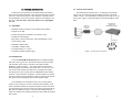
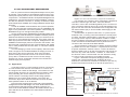
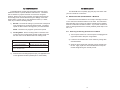
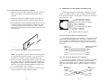
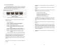
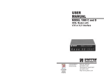
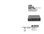
USER
MANUAL
MODEL IM1/I4
Ethernet Bridge with
Integral 4-Port Hub
QuikConnect™ Module
Part# 07MIM1/I4-C
Doc# 090141UC
Revised 07/19/00
CERTIFIED
An ISO-9001
Certified Company
SALES OFFICE
(301) 975-1000
TECHNICAL SUPPORT
(301) 975-1007
http://www.patton.com
1.0 WARRANTY INFORMATION
1.3 SERVICE
Patton Electronics warrants all Model IM1/I4 components to be
free from defects, and will—at our option—repair or replace the product
should it fail within one year from the first date of shipment.
This warranty is limited to defects in workmanship or materials, and
does not cover customer damage, abuse or unauthorized modification.
If this product fails or does not perform as warranted, your sole
recourse shall be repair or replacement as described above. Under no
condition shall Patton Electronics be liable for any damages incurred
by the use of this product. These damages include, but are not limited
to, the following: lost profits, lost savings and incidental or consequential damages arising from the use of or inability to use this product.
Patton Electronics specifically disclaims all other warranties,
expressed or implied, and the installation or use of this product shall be
deemed an acceptance of these terms by the user.
1.1 RADIO AND TV INTERFERENCE
The Model IM1/I4 generates and uses radio frequency energy, and
if not installed and used properly—that is, in strict accordance with the
manufacturer’s instructions—may cause interference to radio and television reception. The Model IM1/I4 has been tested and complies with
the limits for a Class A computing device in accordance with the specification in Subpart J of Part 15 of FCC rules, that are designed to provide
reasonable protection from such interference in a commercial installation. However, this is no guarantee that interference will not occur in a
particular installation. If the Model IM1/I4 does cause interference to
radio or television reception, which can be determined by disconnecting
the unit, the user is encouraged to try to correct the interference by one
or more of the following measures: moving the computing equipment
away from the receiver, reorienting the receiving antenna and/or plugging the receiving equipment into a different AC outlet (such that the
computing equipment and receiver are on different branches). In the
event the user detects intermittent or continuous product malfunction
due to nearby high power transmitting radio frequency equipment, the
user is strongly advised to use only a shielded twisted pair data cable
that is bonded to metalized external outer shield plugs at both ends.
The use of a shielded cable satisfies compliance with the
Electromagnetic Compatibility (EMC) directive.
All warranty and nonwarranty repairs must be returned freight prepaid and insured to Patton Electronics. All returns must have a Return
Materials Authorization number on the outside of the shipping container. This number may be obtained from Patton Electronics Technical
Support at: (301) 975-1007, http://www.patton.com; [email protected].
NOTE: Packages received without an RMA number will not
be accepted.
Patton Electronics’ technical staff is also available to answer any
questions that might arise concerning the installation or use of your
Model IM 1/I4. Technical Support hours: 8AM to 5PM EST, Monday
through Friday.
WARNING!
This device is not intended to be connected to the public telephone network.
1.2 CE NOTICE
The CE symbol on your Patton Electronics equipment indicates
that it is in compliance with the Electromagnetic Compatibility (EMC)
directive and the Low Voltage Directive (LVD) of the Union European
(EU). A Certificate of Compliance is available by contacting Patton
Technical Support.
1
2
2.0 GENERAL INFORMATION
Thank you for your purchase of this Patton Electronics product.
This product has been thoroughly inspected and tested and is warranted for One Year parts and labor. If any questions or problems arise
during installation or use of this product, please do not hesitate to contact us at: (301) 975-1007, http://www.patton.com; [email protected].
2.3 TYPICAL APPLICATION
The Model IM1/I4 QuickConnect™ is designed to plug directly
into the rear of a Patton Electronics baseband modem (e.g. Model
1092A or 1095). The Model IM1/I4 is designed to be used as one of a
pair of units. Figure 1 (below) illustrates a typical Model IM1/I4 installation.
2.1 FEATURES
Rack Mounted
1095RC with
IM2RC Bridge Module
1095 with
IM1/I4 Hub
Module
• Standard interface module for use in QuikConnect platform
• Integral 4-Port HUB
• Industry standard RJ-45 10Base-T connections (four)
• Transparent LAN bridging
10Base-T
Workstations
• PPP (Point to Point Protocol RFC 1661) with Bridging Control
10Base-T
Ethernet
Protocol (RFC 1638)
• 4096 MAC address table
LAN
• 1 MB RAM; 128 KB FLASH
• Throughput latency of 1 frame
• Automatic LAN MAC address aging
Figure 1. Typical Model IM1/I4 application
2.2 DESCRIPTION
The Patton Model IM1/I4 QuikConnect™ is an Ethernet Bridge
with built-in four (4) port hub. The IM1/I4 interface module provides
LAN extension when used in conjunction with either the IM1/I,
IM2RC/IA, or IM1/I4 modules. The module performs transparent
Ethernet bridging and functions at the MAC level. As such, the module, and its communications infrastructure, is transparent to higher
level protocols such as TCP/IP, DECnet, NETBIOS and IPX network
protocols. Only broadcasts, multicasts, or frames destined for peered
LAN are forwarded. The Model IM1/I4 is 802.3 compliant and supports
PPP (RFC 1661) with Bridging Control Protocol (RFC 1638).
Once installed in the local Patton base unit, the Patton IM1/I4
works in a “plug and play” manner to forward LAN broadcasts, multicasts and frames destined for the peered Ethernet LAN at the remote
end (the Patton base unit at the remote end must be equipped with an
IM/I, IM1/I4 or IM2RC/I module). Using the Patton IM1/I4, Ethernet
LANs can be linked over leased 2-wire/4-wire, DDS, PCM and campus
fiber circuits.
3
4
Patton
IM1/I4
Bridge
3.0 PPP OPERATIONAL BACKGROUND
PPP is a protocol used for multi-plexed transport over a pointto-point link. PPP operates on all full duplex media, and is a symmetric peer-to-peer protocol, which can be broken into three main
components: 1. A standard method to encapsulate datagrams over
serial links; 2. A Link Control Protocol (LCP) to establish, configure,
and test the data-link connection; 3. A family of Network Control
Protocols (NCPs) to establish and configure different network layer
protocols.
In order to establish communications over a point-to-point link,
each end of the PPP link must first announce its capabilities and
agree on the parameters of the link’s operation. This exchange is
facilitated through LCP Configure-Request packets.
Once the link has been established and optional facilities have
been negotiated, PPP will attempt to establish a network protocol.
PPP will use Network Control Protocol (NCP) to choose and configure one or more network layer protocols. Once each of the network layer protocols have been configured, datagrams from the
established network layer protocol can be sent over the link. The
link will remain configured for these communications until explicit
LCP or NCP packets close the link down, or until some external
event occurs.
The PPP Bridging Control Protocol (BCP), defined in RFC
1638, configures and enables/disables the bridge protocol on
both ends of the point-to-point link. BCP uses the same
packet exchange mechanism as the Link Control Protocol
(LCP). BCP is a Network Control Protocol of PPP, bridge
packets may not be exchanged until PPP has reached the
network layer protocol phase.
3.1 Applications
In situations where a routed network requires connectivity
to a remote Ethernet network, the interface on a router can
be configured as a PPP IP Half Bridge. The serial line to the
remote bridge functions as a Virtual Ethernet interface, effectively extending the routers serial port connection to the
remote network. The bridge device sends bridge packets
(BPDU's) to the router's serial interface. The router will
receive the layer three address information and will forward
these packets based on its IP address.
Figure 2 shows a typical Cisco router with a serial interface
configured as a PPP Half Bridge. The router serial interface uses
a remote device that supports PPP bridging to function as a
node on the remote Ethernet network. The serial interface on the
Cisco will have an IP address on the same Ethernet subnet as
the bridge.
5
Router
Ethernet LAN
PEC Device w/ Serial I/F
Figure 2. Cisco router with serial interface, configured as PPP Half Bridge.
For example, the customer site is assigned the addresses
192.168.1.0/24 through 192.168.1.1/24. The address
192.168.1.1/24 is also the default gateway for the remote network. The above settings remove any routing/forwarding intelligence from the CPE. The associated Cisco configuration will
set serial interface (s0) to accommodate half bridging for the
above example.
Authentication is optional under PPP. In a point-to-point
leased-line link, incoming customer facilities are usually fixed
in nature, therefore authentication is generally not required. If
the foreign device requires authentication via PAP or CHAP,
the PPP software will respond with default Peer-ID consisting
of the units Ethernet MAC address and a password which
consists of the unit’s Ethernet MAC address.
Some networking systems do not define network numbers
in packets sent out over a network. If a packet does not have
a specific destination network number, a router will assume
that the packet is set up for the local segment and will not forward it to any other sub-network. However, in cases where
two devices need to communicate over the wide-area, bridging can be used to transport non-routable protocols.
Figure 3 illustrates transparent bridging between two
routers over a serial interface (s0). Bridging will occur
between the two Ethernet Interfaces on Router A (e0 and e1)
and the two Ethernet Interfaces on Router B (e0 and e1).
!
no ip routing
!
interface Ethernet0
ip address 1.1.1.1 255.255.255.0
bridge-group 1
!
interface Serial0
ip address 1.1.1.1 255.255.255.0
encapsulation PPP
bridge-group 1
!
interface Serial1
ip address 2.2.2.2 255.255.255.0
bridge-group 1
!
bridge 1 protocol ieee
!
Router A
Serial Interface
Patton DSL Modem
with Ethernet Interface
S0
S1
e0
LAN
LAN
Using Bridge-Groups, multiple remote LANs can be
bridged over the wide-area.
Router B
S1
S0
e0
LAN
LAN
e1
LAN
Serial Interface
Figure 3. Transparent bridging between two routers over a serial link.
6
3.0 CONFIGURATION
The Model IM1/14 module plugs into Patton’s fiber and copper
baseband modems to provide Ethernet LAN extension. The IM1/14
has no switches or jumpers and does not need to be configured.
However, factors such as type of medium, throughput across the link
and clocking mode must be determined by the settings of the baseband modems. Please refer to your baseband modem (i.e. 1092A,
1095, etc) to make the following settings.
1)
Bit Rate: The DTE rate setting of your base unit corresponds
to the throughput of your IM1/14 bridge module. Use higher
speeds to allow maximum throughput to your extended LAN.
4.0 INSTALLATION
The Model IM1/I4 is completely plug and play. This section tells
you how to make the connections.
4.1 INSTALLING THE QUICKCONNECT™ MODULE
Each Quick Connect Module™ has a 50-pin card edge connector
on one side and an ethernet interface on the other. The instructions
below describe how to remove the existing QuickConnect™ Module
and how to install the new IM1/I4 module. If your base unit does not
have an existing QuickConnect™ already installed, please skip to section 4.1.2.
NOTE: The IM1/14 only supports synchronous speeds.
4.1.1 Removing the Existing QuickConnect™ Module
2)
Clocking Mode: Set the clocking modes on the base units
so that one unit is configured for Internal clocking mode and
the other unit is set for Receive Recover clocking mode.
BASE UNIT CLOCK MODES
Unit “A”
Unit “B”
Internal Clock Setting
Receive Recover Clock Setting
NOTE: Unit “A” and Unit “B” are arbitrarily chosen. It does not matter which
unit is “A”, and which is “B”.
3)
1) Turn the power switch off. Leave the power cord plugged into
a grounded outlet to keep the unit grounded.
2) Loosen the two thumbscrews on the module by turning them
counterclockwise.
3) Grasp the two thumbscrews and gently pull the module from
the unit. Apply equal force to the thumbscrews to keep the
module straight during the removal process
All other base unit settings depend upon your application and
on the application medium (twisted pair or coaxial cable)
7
8
4.2 CONNECTING TO THE 10BASE-T ETHERNET PORT
4.1.2 Installing the New QuickConnect™ Module
1) Make sure the power switch on the base unit is off. Leave the
power cord plugged into a grounded outlet to keep the unit
grounded.
2) Hold the module with the faceplate toward you and align the
module with the guide slots in the rear panel of the base unit.
3) While keeping the module’s faceplate parallel with the base unit
rear panel, slide the module straight in–so that the card edge
contacts line up with the socket inside the chassis. Figure 4
(below) shows how a Quick Connect Module plugs into the rear
of the base unit.
The RJ-45 Ethernet port on Model IM1/I4 is designed to connect
directly to a 10BaseT network. Figure 5, below, shows the 10BaseT
RJ-45 port pin description. You may make connections up to 330 feet
using Type 4 or 5 cable.
1 RD+ (data input to IM1/I4)
2 RD- (data input to IM1/I4)
1
3 TD+ (data output from IM1/I4)
2
3
4 (no connection)
4
5
5 (no connection)
6
6 TD- (data output from IM1/I4)
7
8
7 (no connection)
8 (no connection)
Figure 5. 10BaseT RJ-45 Port Pin Description
4.2.1 Connecting the Hub Ports to Workstations
The Model IM1/I4 10Base-T hub interfaces are configured as DCE
(Data Circuit Terminating Equipment). Therefore, it “expects” to connect to a 10Base-T workstation using a straight-through RJ-45 cable.
Use the diagram below to construct a cable to connect the IM1/I4 to a
workstation.
Figure 4. Installation of Model IM1/I4 Plug-in Serial Interface Module
NOTE: The card edge connector should meet the socket when
it is almost all the way into the chassis. If you encounter a lot
of resistance, remove the module and repeat steps 2 & 3.
4) With the card edge contacts aligned with the socket, firmly seat
the module by using your thumbs to apply pressure directly to
the right and left edges of the module faceplate. Applying moderate and even pressure should be sufficient to seat the module. You should hear it “click” into place.
5) To secure the module in place, push the thumbscrews into the
chassis and turn the screws clockwise to tighten.
IM1/I4
RJ-45 Pin No.
1 (RD+)
2 (RD-)
10BaseT Workstation
RJ-45 Pin No.
1 (TD+)
2 (TD-)
3 (TD+)
6 (TD-)
3 (RD+)
6 (RD-)
4.2.2 Connecting the Hub Ports to a Hub (DCE)
The Model IM1/I4 10Base-T interface is configured as DCE (Data
Circuit Terminating Equipment). If you wish to connect the IM1/I4
10Base-T ports to another hub (or a 10Base-T port that “looks like” a
hub), refer to the diagram below to construct a 10Base-T “crossover”
cable.
IM1/I4
Hub
RJ-45 Pin No.
RJ-45 Pin No.
1 (RD+)
1 (RD+)
2 (RD-)
2 (RD-)
3 (TD+)
6 (TD-)
9
3 (TD+)
6 (TD-)
10
N
5.0 OPERATION
4.3 CONNECTION TO THE LINE INTERFACE MEDIA
Instructions for connecting the line interface media (twisted pair, or
fiber optic cable) are contained within the base unit user manual.
Please refer to the base unit manual for connection details.
Once the Model IM1/14 is installed, it should operate transparently. This sections describes power-up, general operating instructions,
and the LED status monitors.
4.4 CONNECTING TO AC OR DC POWER
5.1 OPERATING INSTRUCTIONS
Instructions for connecting the power supply Universal Interface
AC Power Supply and DC Power Supply option) are contained within
the base unit user manual. Please refer to the base unit manual for
connection details.
In order to operate, the Model IM1/I4 must be installed in the base
unit. It also requires a 10Base-T connection. After power is applied,
the IM1/I4 automatically starts performing the bridging function without
further user intervention. MAC addresses discovered are automatically
loaded into the MAC address table. They are automatically deleted
from the MAC address table if they experience an inactivity of 8 minutes.
WARNING! The Model IM1/I4 interface card has been
specifically designed to work with UI and DC versions of
Patton Electronics base units. Use with 120/230VAC versions could result in damage to the unit. If you are unsure
of your base unit power supply, please contact Patton
Electronics technical support at (301) 975-1007 or at [email protected].
11
5.2 POWER-UP
Before applying power to the IM1/I4, please be sure it is properly
installed in the base unit. Then make sure that unit is connected to
the appropriate power source (Universal Interface AC Power Supply
or DC Power Supply). Then power-up the base unit using the rear
power switch .
12
5.3 LED STATUS MONITORS
The Model IM1/I4 features two LEDs that monitor general operating status and the 10Base-T twisted pair link integrity. Figure 6 (below)
shows the LEDs located directly beneath the RJ-45 jack. Following
Figure 6 is a description of each LEDs function.
TP1 COL
TP2 [Green] - On indicates that port 2 is receiving link integrity or
a packet.
WANF [Yellow] - On indicates that a WAN failure has occurred. A
WAN failure is defined to be any of the following:
Quick-Connect Interface Module
SYS
COL [Yellow] - On pulse indicates that collisions are detected in
the LAN.
TP2 WANF TP3 BSAT
TP4
Figure 6. Model IM1/I4 Panel Showing RJ45 Jacks and LEDs
SYS [Yellow] - Pulses on to indicate one of eleven conditions.
They are as follows:
1
2
3
4
5
6
Pulse = Status OK
Pulses = Detected No LAN Source MAC Addresses
Pulses = Detected No WAN CTS or DCD Signal
Pulses = Detected Buffer Saturation
Pulses = Detected WAN Receive Frame(s) Too Large
Pulses = Detected WAN Receive Frame(s) Not Octet
Aligned
7 Pulses = Detected WAN Receive Frame(s) Aborted
8 Pulses = Detected WAN Receive Frame(s) With Bad CRC
9 Pulses = Detected LAN Receive Frame(s) Too Large
10 Pulses = Detected LAN Receive Frame(s) Not Octet
Aligned
11 Pulses = Detected LAN Receive Frame(s) With Bad CRC
•
•
•
•
•
No WAN CTS or DCD Signal
WAN Receive Frame(s) Too Large
WAN Receive Frame(s) Not Octet Aligned
WAN Receive Frame(s) Aborted
WAN Receive Frame(s) With Bad CRC
The WANF LED is on while the condition(s) persist. After all conditions are removed the WANF LED continues to be on for 60
seconds after the failure condition(s) are represented on the SYS
LED.
TP3 [Green] - On indicates that port 3 is receiving link integrity or
a packet.
BSAT [Yellow] - On indicates that all buffer memory reserved for
user data has been saturated (used up). This condition may exist
for only a brief moment and is completely recoverable. After the
buffer saturation condition is removed the BSAT LED continues to
be on for 60 seconds after the buffer saturation condition is represented on the SYS LED.
TP4 [Green] - On indicates that port 4 is receiving link integrity or
a packet.
A given status code will be displayed 8 times until another status
code will be displayed. The unit will check all status conditions
attempting to indicate as many status codes as possible in
sequential order. After a status code is displayed 8 times and the
associated condition is removed the status code will no longer
appear.
TP1 [Green] - On indicates that port 1 is receiving link integrity or
a packet.
13
14
APPENDIX A
PATTON MODEL IM1/I4 SPECIFICATIONS
LAN Connection:
RJ-45, 10Base-T, 802.3 Ethernet
Protocol:
PPP (RFC 1661) with Bridging Control
Protocol (RFC 1638)
MAC Address Table Size:
4096 entries
MAC Address Aging:
MAC addresses deleted after 8 minutes inactivity
On-board Memory:
1 MB RAM; 128 KB FLASH
Frame Latency:
1 frame
Interface:
card-edge connection to
QuikConnect™ port on Patton base
unit
Base Unit Compatibility:
1092, 1092A, 1093, 1094, 1094A,
1095, 1184, and 1185
LED Indicators:
SYS, TP1, COL, TP2, WANF, TP3,
BSAT, and TP4
Power Supply:
+5 Volts @ 510 mA supplied to module
by connection to Patton QuikConnect
interface
Temperature Range:
32 to 122ºF (0 to 50º C)
Dimensions:
2.9" x 3.2" (7.4 cm x 8.1 cm)
Weight:
0.25 lb (0.11 kg)
APPENDIX B
IM1/I4 INTERFACE PIN ASSIGNMENT
10BASE-T Interface Pin Description
(RJ-45 Female Connector)
(Hub Configuration)
Pin #
1
2
3
4
5
6
7
8
Signal
RD + (data input to IM1/I4)
RD - (data input to IM1/I4)
TD + (data output from IM1/I4)
no connection
no connection
TD - (data output from IM1/I4)
no connection
no connection
© Copyright 2000
Patton Electronics Company
All Rights Reserved
15
16