1
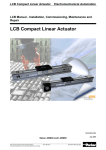
Automation
Linear actuators
HLE with timing belt drive
HLEZ with rack-and-pinion drive
Catalogue: 192-510011N7
Version 7 / May 1999
HLE – Linear actuators with timing belt drive
Automation
2
Parker Hannifin GmbH
Electromechanical Division
HLE – Linear actuators with timing belt drive
HLE linear actuators with timing belt drive
- for guiding, transporting and positioning Contents:
The HLE - a proven technology.............. 4
Construction of the HLE.......................... 5
Technical data .......................................... 6
Dimensional drawings ............................. 8
HLE 80...................................................... 8
HLE100................................................... 10
HLE 150.................................................. 12
Idler unit................................................. 14
Carriage with bar .................................. 14
Order code ............................................. 15
HLEZ linear actuators with rack-andpinion drive............................................. 17
Mechanical accessories ........................ 25
Assembly angle plate ........................... 25
Clamping profile ................................... 26
T-nuts and bolts.................................... 26
Link shaft bearing................................. 27
External buffer stop.............................. 27
Cable carrier.......................................... 28
Longitudinal flange connection set .... 30
Attachment of position sensors .......... 31
Tripping plate........................................ 32
Mechanical limit switch........................ 33
Electrical limit switch ........................... 33
Distribution box .................................... 34
Other accessories and software........... 34
The dynamic linear unit
Typical fields of application
Proven technology
for guiding, transporting and positioning, even over long distances,
offers:
as part of advanced, cost-effective construction of machines and
handling systems:
i
i
proven in numerous applications,
offers the following advantages:
i Low-friction running guaranteed:
i
i
i
i
i
i
i
High speeds in practical applications of up to 7 m/s
Up to 108 Nm permitted driving torque
Long travel distances, up to
20 m
High load capacity, horizontal
up to 1000 kg /, vertical up to
300 kg
Repeatability, up to ±0.05 mm
High mechanical efficiency of
95 %
Three profile sizes: HLE80,
HLE100 and HLE150, can be
combined in a modular system
Simple, rapid installation and
start-up
i
i
i
i
i
i
i
i Low particle generation (clean
Materials handling e.g. palletization, feeding, withdrawal
Textile machinery building
e.g. cross-cutting, slitting and
stacking, quilting, seam stitching
Process engineering e.g.
painting, coating, bonding
Warehouse technology e.g.
picking, storage
Construction e.g. formwork,
placing reinforcing steel
Clean room technology e.g.
wafer transport, wafer coating
Machine tool building e.g.
loading with workpiece, tool
changing
Testing technology e.g.
guiding ultrasonic sensors
room suitability to class 10)
i
i
i
i
i
i low wear
i zero maintenance
i quiet running
i high efficiency and
i long service life
High dynamic performance
due to low-mass, play-free
wheels
Simplified inspection with long
inspection intervals.
Longitudinal grooves integrated on all sides of the profile
for mounting attachments or
for use as a cable duct
Timing belts can be replaced
without dismantling load attachment plate.
Flexible installation options
provided by longitudinal grooves in the load attachment
plate.
Subject to technical modification. Data correct at time of printing
Automation
06/99
3
Parker Hannifin GmbH
Electromechanical Division
HLE – Linear actuators with timing belt drive
The HLE - a proven technology
The universal one
Our experience
The HLE linear actuator offers an appropriate solution for all motion tasks.
It is ideal for use as a single axis, or as
a component in a multiple axis system.
It has been developed for rapid linear
movements over long stroke distances.
The HLE provides a simple machine
and system element and can be used
without the need for any specialised
knowledge. Installation and starting up
only requires a small amount of effort
from the user. The HLE is supplied in
many different configurations with numerous options and many accessories.
You can have confidence in our experience and skill because over 6000 axes
are already in use throughout the world
- be it in automatic textile equipment,
handling systems, packaging machines, automatic painting and binding
equipment ...etc.
The HLE can be found in a wide range
of applications: in clean rooms, in the
food industry, production plants in the
chemical industry or in the manufacture
of prefabricated concrete components.
We work together with a wide range of
different industrial sectors including the
automobile industry, machine tool
manufacturers, microelectronics manufacturers - and hopefully soon with you
...
Examples/applications
i Mercedes Benz, Sindelfingen, Germany:
supporting cockpit parts in the S-class
i IBM, Böblingen, Germany: wafer transport
in chip production
i Bosch-Siemens Hausgeräte GmbH,
Traunreut, Germany: handling cookers
i SEL, Stuttgart, Germany: picking electronic
components
i Bayer, Bitterfeld: palettising folding cartons
(flatpack boxes) for pharmaceuticals
i LT Engineering, Switzerland: shelf-picking
unit for small parts stores
i Braas, Steinfeld: handling roof tiles
i Philips, Holland: handling screen masks
i Weckenmann, Dormettingen: setting shell
profiles in the concrete branch.
The HLE drive principle
The HLE consists of an extruded, selfsupporting aluminium profile, inside
which a backlash-free wheeled carriage
is moved by a timing belt.
The steel cord tensile strands integrated into the belt provide the necessary stiffness and effectively prevent
belt streching.
Special pulleys ensure play-free drive,
ensuring high repeatibility even with
long travel paths and high speeds.
liably protects the timing belt, wheels
and the bearing surface of the profile
against dirt (protection class IP30).
Optional steel strip cover
A totally new steel strip cover concept
applies fully to the HLE-design. It reThe T-grooves of the load attachment plate and the basic HLE profile are suitable for T-nuts in accordance with DIN508 and T-bolt in
accordance with DIN 787 (T-nuts
and bolts: refer to page 26)
Steel plate integrated in the carriage Protective caps ensure that no dust
plate serves as switching plate for
enters the interior of the HLE
home & limit sensors.
Magnetic strips recessed in the
profile ensure that the steel belt is
fully sealed with the profile
Switches or sensors for the end
limit or for the machine zero point
can be integrated in the T-groove of
the HLE profile
Automation
Plastic inlays serve as
bearing surface for steel
strip.
4
A spring-loaded felt insert reliably
keeps dirt away
The timing belt is attached to the carriage
with a clamping angle piece.
The belt can be changed without dismantling the flange plate.
Parker Hannifin GmbH
Electromechanical Division
HLE – Linear actuators with timing belt drive
Construction of the HLE
4
1
9
5
7
6
3
8
2
The timing belt has no play and is reinforced
by integral steel wires, thereby ensuring maximum travel speeds and repeatability.
When used in conjunction with the
clamping profile (page 26) this allows for
simple incorporation in a multi-axis system.
i Simple and adjustable attachment of operating cams or switch lugs by means of
longitudinal grooves on the sides and on
the underside of the plate.
i Height and bolt points are unaffected when
the steel strip cover is attached at a later
date.
Special designs are also available on request.
Clamping of timing belt (6)
The optional drive motor (9)
The timing belt clamping angle guarantees a
secure connection between the timing belt and
the carriage.
The clamping system allows the timing belt to
be replaced without the load attachment plate
having to be dismantled. This means that attachments do not normally need to be removed.
Parker servo motor with resolver and an appropriate planetary gearbox form an optimum
drive for dynamic and accurate applications.
When used together with the COMPAX compact servo controller, the HLE becomes a
complete, ready-to-run automation system for
single and multi-axis travel and continuous
path controls.
The load attachment plate (7)
The V2A version (option V)
The profile (1)
The drive station (4)
Light, compact and self-supporting aluminium
profile construction. Available in the following
cross-sections:
Robust cast casing with standard flange. Many
gearboxes can be directly flange-mounted (for
bore pattern, refer to dimensions).
On request, this can be supplied with the drive
shaft on the right, on the left or on both sides.
80x80 mm
100x100 mm
150x150 mm
(HLE80)
(HLE100)
(HLE150)
All profiles feature a total of eight longitudinal
clamping grooves for the attachment of additional mechanical components and for the
connection of several HLE units. These
grooves also serve as attachment and mounting points for initiators and mechanical switches.
Together with the HAUSER cover profiles (8),
these can be used as cable ducts.
The carriage (2)
Light, rigid carriages with plastic rollers
mounted on roller bearings and eccentric axles
for play-free carriage settings on all sides.
Overall, this results in high mechanical efficiency and virtually wear-free operation. The
carriage can be supplied in two lengths, either
standard or extended.
We can also produce special carriages for
customised applications.
The timing belt (5)
i
The longitudinal grooves integrated on
the top of the plate offer many options for
the assembly of attachments.
The tensioning station (3)
An easily maintained and assembly-friendly
tensioning station for setting the tension required for the timing belt and its orientation
(parallelism of pulleys).
Automation
5
Minimum particle emissions and high levels of
resistance to water and various cleaning
agents make the V2A version the number one
choice for use in clean rooms or the food industry.
The steel components are made of V2A material and the rollers and pulley mountings are
fitted with corrosion-resistant bearings.
Parker Hannifin GmbH
Electromechanical Division
HLE – Linear actuators with timing belt drive
Technical data
HLE size
80
100
150
Unit
Standard
Steel strip
cover
Standard
Steel strip
cover
Standard
Steel strip
cover
HLE with standard carriage S
kg
7.1
7.9
11.5
12.7
28.6
31.2
HLE with extended carriage E
Weight of standard carriage +
load attachment plate S
Weight of extended carriage +
load attachment plate E
Weight per meter of additional length
kg
8.4
9.9
14.6
15.8
35.9
38.5
kg
1.5
1.7
2.5
2.8
6.7
7.3
kg
2.5
2.8
4.1
4.4
10.9
11.5
kg/m
6.4
6.4
9.9
10.0
21.0
21.1
Weight and moment of inertia
Weight of basic unit without stroke
Moment of inertia related to the drive shaft
Standard carriage S
kgcm2
18.1
20.3
22.3
24.6
114.0
123.3
Extended carriage E
kgcm2
27.5
29.7
34.1
36.4
174.4
183.6
Travel paths and speeds
1
m/s
1
2
Maximum travel speed
Maximum acceleration
Maximum travel path, standard
2
carriage S/T with one profile bar
Maximum travel path, extended
2
carriage E/F with one profile bar
m/s
5.0
5.0
5.0
10.0
10.0
10.0
mm
5350
5260
6300
6210
9150
9060
mm
5200
5110
6150
6060
9000
8910
Geometrical data
Cross-section
mm x mm
80 x 80
100 x 100
150 x 150
Moment of inertia Ix
cm4
152
383
1940
Moment of inertia Iy
cm4
177
431
2147
Moment of inertia It
cm4
24
117
Modulus of elasticity
391
5
N/mm2
0.72*10
Pulley data, torques and forces
Travel distance per revolution
Pulley diameter
Nominal drive torque
3
Maximum drive torque
Nominal belt traction (effective load)
3
Max. belt traction (effective load)
Repeatability
4
mm/rev
190
170
240
mm
60.479
54.113
76.394
Nm
17.5
15.7
51.4
Nm
32
40
108
N
580
580
1350
N
1058
1478
2827
mm
±0.2
±0.2
±0.2
Please contact HAUSER in the event of the following deviations from the standard technical data:
1
2
Travel speeds over 5m/s and acceleration over 10m/s .
2
Longitudinal flange connection possible for longer travel distances. This does lead to limitations with regard to: maximum
permitted load, drive torque, speed, acceleration and repeatability (refer to page 30)
3
Increased timing belt tension required.
4
Repeatability up to ± 0.05 mm
Technical data, issued 06/99, safety factor taken into consideration S=1. Data applies for a temperature range of between -10°C and +40°C
Automation
6
Parker Hannifin GmbH
Electromechanical Division
HLE – Linear actuators with timing belt drive
Mz
Fz
Fx
Mx
Fy
My
Fx [N] (load-bearing capacity of timing belt)
3000
The forces and torques the carriage and the timing belt are
capable of transferring are speed-dependent.
The curves shown in the graphs apply to a standard carriage
(S/T).
With the extended carriage (E/F), all the values apart from
Fx (load-bearing capacity of timing belt) can be doubled if
the load is applied equally to both halves of the carriage or
distributed uniformly along its entire length.
The curves show the maximum load-bearing capacity of a
carriage in one direction of force or torque. If several loads
are applied in different directions, the values given by the
curves must be derated, i.e. the load or speed should be
reduced if necessary.
For precise carriage dimensioning, our software "DimAxes"
is available (Refer to "Other accessories and software", page
34).
Mx [Nm]
250
HLE150c
2500
200
HLE150c
2000
150
HLE100c
1500
100
1000
HLE100c
HLE80c
50
500
HLE80c
0
0
0
1
2
3
4
v [m/s]
0
5
Fy [N]
1
2
3
4
2
3
4
3
4
v [m/s]
5
My [Nm]
1800
450
1600
400
HLE150c
1400
350
1200
300
1000
250
HLE100c
800
HLE150c
HLE100c
200
600
150
400
HLE80c
100
HLE80c
200
50
0
0
0
1
2
3
4
v [m/s]
5
0
Fz [N]
Mz [Nm]
3500
250
v [m/s]
5
HLE150c
HLE150c
3000
1
200
2500
150
2000
HLE100c
1500
HLE100c
100
1000
50
HLE80c
500
HLE80c
0
0
0
1
2
Automation
3
4
v [m/s]
0
5
7
1
2
v [m/s]
Parker Hannifin GmbH
Electromechanical Division
5
34+0,2
50
100
Automation
40+0,2
50
8
61
122
140
80
164 (209)
110H7
Pulley for drive shaft Ø25
Key complying with
DIN 6885 T1, type A
gearbox flange Q
(35)
stroke
M5
70
120
100
7
125
Safety
travel
4,5+0,3
12,5+0,2
Slots compatible with
DIN508 T-nuts
DIN787 T-bolts
Detail X
80
40±0,3
70
8,1+0,3
X
50
12,5+0,2
4,5+0,3
8,1+0,3
100
Dimensions in () apply in combination with
steel strip cover. Parts indicated in broken lines:
Steel strip cover option. Casing projection at drive
and tensioning station approx. 1mm.
106
130 (175)
Pulley for drive shaft Ø16
Key complying with
DIN 6885 T1, type A
Ø60 H
±0,1
Ø75
5x45°
gearbox flange A
Pulley for drive shaft Ø20
A
A
250 standard carriage
400 extended carriage
40±0,3
gearbox flange R
120
70
(35)
125
Safety
travel
20
4xM8 Pitch
circle Ø130
Timing belt
tensioning screws
4xM6 Pitch
circle Ø100
80H7
144 (189)
Section A-A enlarged
HLE – Linear actuators with timing belt drive
Dimensional drawings
HLE 80 single axis
100
50
10
52
Parker Hannifin GmbH
Electromechanical Division
HLE – Linear actuators with timing belt drive
100
40
87
SR
SL
40
50
100
50
100
50
HLE80 drive housing with drive shafts
29
87
96
20h6
20h9
70
120
20h8
70
70
120
120
SL: shaft on left
SR: shaft on right
SB: shafts on both sides
RL: gearbox on right and
shaft on left
LR: gearbox on left and shaft
on right
100
50
100
50
100
50
HLE 80 dual axis with gearbox flange Q
80
A > 500
215 < A < 500
80
80
80
215
70
70
120
70
120
120
Centre distance A between 80215 mm
Centre distance A between
215-500 mm
Centre distance A greater than
500 mm
122
61
122
61
61
122
HLE 80 dual axis with gearbox flange R
A > 500
A > 215
80
80
80
80
215
80
80
80
140
140
140
Centre distance A between 80215 mm
Automation
Centre distance A between
215-500 mm
9
Centre distance A greater than
500 mm
Parker Hannifin GmbH
Electromechanical Division
132
Automation
4xM8 Pitch
circle Ø130
64,4
63,4±0,2
52
10
85
150
85
±0,1
64,4
132
4,5+0,3
132
64,4
8,1+0,3
Detail X
100
60±0,3
90
Dimensions in () apply in combination with
steel strip cover. Parts indicated in broken lines:
Steel strip cover option. Casing projection at drive
and tensioning station approx. 1mm.
Pulley for drive shaft Ø16
Key complying with
DIN 6885 T1, type A
Slots compatible with
DIN 508 T-nuts
DIN 787 T-bolts
102
126(171)
12,5 +0,2
Ø6
0 H7
Ø75
5x45°
125
Safety
travel
12,5+0,2
4,5+0,3
X
8,1+0,3
Pulley for drive shaft Ø20
Key complying with
DIN 6885 T1, type A
M5
100
gearbox flange A
gearbox flange R
(35)
stroke
20
150
A
A
Pulley for drive shaft Ø25
Key complying with DIN 6885 T1, type A
(35)
300 standard carriage
450 extended carriage
60±0,3
80H7
174(219)
gearbox flange Q
150
85
125
Safety
travel
120
8xM6 Pitch
circle Ø100
Timing belt
tensioning screw
43+0,2
110H7
174(219)
Section A-A enlarged
HLE – Linear actuators with timing belt drive
HLE100 single axis
52
12
52
Parker Hannifin GmbH
Electromechanical Division
HLE – Linear actuators with timing belt drive
40
87
40
87
SR
132
64,4
132
64,4
132
64,4
HLE100 drive housing with drive shafts
40
87
20h6
SL
20h9
85
150
20h8
85
150
85
150
SL: shaft on left
SR: shaft on right
SB: shaft on both sides
RL: gearbox on right and
shaft on left
LR: gearbox on left and shaft
on right
132
64,4
132
64,4
64,4
132
HLE 100 dual axis with gearbox flanges Q and R
A > 500
100
225
85
150
85
150
Centre distance A between
100-225 mm
Automation
100
85
150
100
100
225<A<500
Centre distance A between
225-500 mm
11
Centre distance A greater than
500 mm
Parker Hannifin GmbH
Electromechanical Division
104
102
Automation
4xM8
TK Ø130
187
Timing belt
tensioning screws
54
115
198
110H7
234(279)
(35)
A
A
350 standard carriage
500 extended carriage
(35)
Dimensions in () apply in combination with
steel strip cover. Parts indicated in broken lines:
Steel strip cover option. Casing projection at drive
and tensioning station approx. 1mm.
gearbox flange R
Pulley for drive shaft Ø25
Key complying with DIN 6885 T1, type A
125
Safety
travel
stroke
110
146(191)
Slots compatible with
DIN508 T-nuts
DIN787 T-bolts
125
Safety
travel
10,1+0,5
12
8+0,5
Detail X
150
90 ±0,3
140
8
X
Section A-A enlarged
HLE – Linear actuators with timing belt drive
HLE 150 single axis
175
90±0,3
25
8
10,1+0,5
8+0,5
60
Parker Hannifin GmbH
Electromechanical Division
HLE – Linear actuators with timing belt drive
187
104
187
104
187
104
HLE150 drive housing with drive shafts
56
108
56
108
SR
SL
45
123
30h9
115
198
30h9
115
150
SL: shaft on left
SR: shaft on right
30h9
115
198
SB: shaft on both sides
RL: gearbox on right and
shaft on left
LR: gearbox on left and shaft
on right
186
104
186
104
104
186
HLE 150 – dual axis with gearbox flange R
260 < A < 500
A > 500
150
115
198
Centre distance A between
150-260 mm
Automation
150
150
150
260
115
115
198
198
Centre distance A between
260-500 mm
13
Centre distance A greater than
500 mm
Parker Hannifin GmbH
Electromechanical Division
HLE – Linear actuators with timing belt drive
Idler unit
L1
10
Carriage length
125
Safety
travel
A
(35)
125
L2
Safety
travel
10
stroke
(35)
The HLE is also available as
a non-driven, idler unit. In this
Section A-A case it acts as a guide only.
The profile cross-section and
carriage dimensions correspond to those for the driven
axes.
Please take dimensions L1
and L2 from the following table:
A
Dimensions in ( ) apply in combination with steel strip cover
HLE80
Dimensions
HLE100
HLE150
L2
L1
L2
L1
L2
Standard
Unit
mm
L1
34
34
34
34
46
46
Steel strip cover
mm
79
79
79
79
91
91
Carriage with bar (type T or F without load attachment plate)
When ordering an HLE without load attachment plate, the bar is used as a replacement for the belt clamp. The
threads in the carriage are accessible through holes in the bar for mounting your own attachments. Diagrams show
the location of tapped holes for load attachment.
HLE80 / HLE100 standard carriage (T)
L1
L1
L2
L2
HLE80 / HLE100 extended carriage (F)
L3
L2
Ø9 (3x)
L3
L2
Ø9 (5x)
L
L
HLE
Unit
L
L1
L2
HLE
Unit
L
L1
L2
L3
80 T
100 T
mm
mm
250
300
75
95
50
55
80 F
100 F
mm
mm
400
450
75
95
75
75
50
55
HLE80 / HLE100 /HLE150
thread.
L1
L2
L3
L2
Ø14 (4x)
T
12
B
4
HLE150 Standard carriage(T) / extended carriage (F)
L
HLE
Unit
L
L1
L2
L3
HLE
Unit
B
T
Thread
150 T
150 F
mm
mm
350
500
75
105
70
100
60
90
80
100
mm
mm
15
25
20
20
M8
M8
150
mm
30
25
M12
Automation
14
Parker Hannifin GmbH
Electromechanical Division
HLE – Linear actuators with timing belt drive
Order code
HLE linear actuator
L E
P
Drive system
Timing belt drive
Idler unit
B
N
Model / size
80 (Dimensional drawing on page 8)
100 (Dimensional drawing on page 10)
150 (Dimensional drawing on page 12)
0
1
1
8
0
5
0
0
0
Carriage
Standard carriage with load attachment plate
Standard carriage with bar
Extended carriage with load attachment plate
Extended carriage with bar
Special carriage with load attachment plate (on request)
Special carriage with bar (on request)
Extras (e.g. two or more carriages)
S
T
E
F
C
D
X
Guide system
Plastic sheathed wheels
P
Stroke
Specify desired stroke (in mm)
n
n
n
n
n
Drive options (refer to figures on page 16)
Shaft on left (Dimensional drawings: refer to pages 9, 11, 13)
Shaft on right (Dimensional drawings: refer to pages 9, 11, 13)
Shaft on both sides (Dimensional drawings: refer to pages 9, 11, 13)
Without drive – prepared for drive to be fitted on left
Without drive – prepared for drive to be fitted on right
Gearbox on left
Gearbox on right
Gearbox on left and shaft on right (Dimensional drawings: refer to pages 9, 11, 13)
Gearbox on right and shaft on left (Dimensional drawings: refer to pages 9, 11, 13)
Without drive – idler unit (Dimensional drawing: refer to page 14)
Extras (others, e.g. central drive with dual axes) (on request)
S
S
S
N
N
D
D
L
R
N
X
L
R
B
L
R
L
R
R
L
N
X
Gearbox flange
Flange suitable for Stöber planetary gears P3
Flange suitable for Stöber planetary gears P4
Flange suitable for Stöber planetary gears P5
Flange suitable for Stöber planetary gears P7
Flange suitable for Stöber planetary gears P4, compatible with PL90
Flange suitable for Stöber planetary gears P5, compatible with PL115
Without drive housing – idler unit
Extras (others, not standard) (on request)
A
B
C
D
Q
R
N
X
Centre distance with dual axes (from centre of axis to centre of axis)
Specify desired centre distance (in mm)
Specify for single axis or idler unit
n
0
n
0
n
0
n
0
n
0
Steel strip cover (refer to page 4)
Without steel strip cover
With steel strip cover (protection class IP30)
N
C
Material version
Standard – version
Corrosion-resistant version (V2A)
N
V
Linear encoder
Without linear encoder (standard)
With linear encoder
Automation
N
L
15
Parker Hannifin GmbH
Electromechanical Division
HLE – Linear actuators with timing belt drive
Drive options
SL
SR
SB
NL
NR
DL
DL (dual axis)
DR
DR (dual axis)
LR
RL
=
A
Automation
16
Parker Hannifin GmbH
Electromechanical Division
NN
HLEZ – linear actuators with rack-and-pinion drive
HLEZ linear actuators with rack-and-pinion drive
- for long travel paths with high rigidity and accuracy
Contents:
The HLEZ - a combined technology......18
Construction of the HLEZ.......................19
Technical data..........................................20
Dimensional drawings ............................22
HLEZ100..................................................22
HLEZ150..................................................22
Gearbox fitting - examples .....................23
HLEZ150 with planetary gearbox P5....23
HLEZ150 with worm gearbox................23
Order code ...............................................24
Mechanical accessories .........................25
Assembly angle plate ............................25
Clamping profile.....................................26
T-nuts and bolts .....................................26
Link shaft bearing ..................................27
External buffer stop ...............................27
Cable carrier ...........................................28
Longitudinal flange connection set .....30
Attachment of position sensors ...........31
Tripping plate .........................................32
Mechanical limit switch .........................33
Electrical limit switch.............................33
Distribution box......................................34
Other accessories and software ............34
The "endless" linear unit
Typical fields of application
The combined technology
for guiding, transporting and positioning over long strokes, offers:
i Long travel distances, up to
50 m
i High speeds in practical applications, up to 5 m/s
i High levels of load capacity,
horizontally up to 1000 kg /
vertically up to 300 kg
i Up to 64 Nm permitted drive
torque
i Repeatability, up to ±0.05 mm
i Several carriages possible on
one linear unit
i Two profile sizes: HLEZ100
and HLEZ150
i Simple, rapid installation and
start-up
as part of advanced, cost-effective construction of machines and
handling systems:
of the linear actuator and rack offers the following advantages:
i High dynamic response, even
over long travel distances, due
to:
i the short timing belt, regardless of travel length
i the lightweight carriage
i the backlash-free drive
i High positional accuracy, regardless of stroke length
i Option of several carriages per
linear unit, making overlapping
strokes along a single axis possible
i Easy servicing at long intervals
i Grooves running in the profiles
on all sides to enable mounting
of the HLEZ to a supporting
structure, fitting attachments or
as cable ducts
i Grooves in the load attachment
plate for flexible installation
i
i
i
i
i
i
i
i
Automation
Materials handling e.g. palletization, feeding, removal
Textile machinery building
e.g. cross-cutting, slitting and
stacking, quilting, seam stitching
Process engineering e.g.
painting, coating, bonding
Storage technology e.g.
commissioning, inventory
Construction technology:
e.g. peeling, laying reinforcement of concrete
Clean room technology e.g.
wafer transport, wafer coating
Machine tool building e.g.
workpiece loading, tool changing
Testing technology e.g.
guiding ultrasonic sensors
17
Parker Hannifin GmbH
Electromechanical Division
HLEZ – linear actuators with rack-and-pinion drive
The HLEZ - a combined technology
The new design
Our experience
Taking the HLE linear units as its
base, a new rack-and-pinion drive
system has been designed for the
HLE100 and HLE150.
The system which is especially
suitable for long travel distances
and high speeds, opens up a
whole range of new application
options. The patented rack principle permits "endless" travel whilst
maintaining high accuracy. At the
same time the dynamic characteristics of the system are outstanding.
When required several carriages
can be positioned on a single unit
independently of each another. In
combination with other HAUSER
mechanical components, this allows the construction of efficient
and cost-effective gantry and
automation systems.
You can have confidence in our
experience and skill because over
6000 linear axes are already in
use throughout the world –
whether it be in automatic textile
equipment, handling systems,
packaging machines, automatic
painting and binding equipment,
etc....
The HLEZ is found across a broad
application area - in clean rooms,
in the food industry, in chemical
production plants and in the production of precast concrete components.
We work together with a wide
range of sectors including the
automobile industry, machine tool
manufacturers, microelectronics
manufacturers - and hopefully
soon with you ...
Examples/applications
i
i
i
i
i
i
i
i
i
i
Sick, Waldkirch: sensor testing
equipment
Desarrollo, Spain: gantry robots for transporting glass fibre
coils
Springs, USA: sewing textiles
Weckenmann, Dormettingen:
wide-area gantry robots for the
precast-concrete industry
AZO, Osterburken: marshalling
equipment
EEW, Schönberg: high-speed
milling centre
Telecom, Switzerland: telephone accessory order picking
system
LT Engineering, Switzerland:
shelf-picking unit for small
parts stores
Allied Signal, USA: sewing airbags
Weber-Haus, Linx: boring and
sawing cut-outs for the mounting of distribution boxes and
socket outlets
HLEZ drive principle
The HLEZ drive offers all the advantages of a rack drive, but without the usual drawbacks. The
short timing belt (which is independent of travel lenght) reduces
belt stretching to an absolute minimum.
The lateral deflection roller pretensions the system and thereby removes backlash. Hold-down rollers ensure that sufficient teeth always remain in mesh. The combination of plastic timing belts and
an aluminium rack-and-pinion is a
safe
and clean drive which requires no
lubrication.
All of this offers the following
advantages:
i
i
i
i
i
i
i
Automation
18
high constant rigidity regardless of the travel or position
Very long travel distances
achievable
high levels of accuracy
high speeds are possible
smooth, low-noise running
no lubrication necessary
any installation position possible
Parker Hannifin GmbH
Electromechanical Division
HLEZ – linear actuators with rack-and-pinion drive
Construction of the HLEZ
2
5
3
4
7
6
1
The profile (1)
Light, compact and self-supporting
aluminium profile construction.
Available in the following crosssections:
100x100 mm (HLEZ100)
150x150 mm (HLEZ150)
All profiles have a total of seven
grooves along their length for
clamping further mechanical components and for joining several
HLEZ and HLE units. These
grooves also serve as attachment
and mounting points for sensors
and mechanical switches.
Together with the cover profiles
(2), these can be used as cable
ducts.
The carriage (3)
Lightweight, rigid carriage with
plastic wheels mounted on roller
bearings (4) and eccentric axles for
playfree carriage settings on all
sides.
Automation
Overall, this results in high mechanical efficiency and virtually wearfree operation. The carriage can be
supplied in two lengths either standard or extended.
We can also produce special carriages for customised applications.
The load attachment plate (5)
The longitudinal grooves integrated
on the top of the plate offer many
options for the assembly of attachments. When used together with
the clamping profiles (refer to page
26) this allows simple incorporation
in a multi-axis system.
Simple and adjustable attachment
of operating cams or switch lugs is
provided by longitudinal grooves
on the sides and on the underside
of the plate.
Special designs are also available
on request.
19
The drive module (6)
Compact drive module, can optionally be supplied fitted on either
side of the load attachment plate.
For a description of the drive principle, refer to page 18.
The optional Parker servo motor
(7) with resolver and an appropriate planetary gearbox forms an
optimum drive for dynamic and
accurate applications.
When used together with the
COMPAX compact servo-controller, the HLE becomes a complete,
ready-to-run automation system for
single and multi-axis travel and
continuous path controls.
Parker Hannifin GmbH
Electromechanical Division
HLEZ – linear actuators with rack-and-pinion drive
Technical data
HLEZ size
Unit
HLEZ100
HLEZ150
Weight and moment of inertia
Weight of basic unit without stroke
HLEZ with standard carriage
kg
22
53
HLEZ with extended carriage
kg
26
61
Weight of standard carriage with
kg
11.3
25.7
load attachment plate and drive
module
Weight of extended carriage with
kg
13.3
29.7
load attachment plate and drive module
Weight per meter additional length
kg/m
11.3
23.9
(guide profile + rack)
*1
Moment of inertia of drive shaft (allowing for carriage with load attachment plate and drive module)
Standard carriage S
Extended carriage E
kgcm2
kgcm2
33.3
37.9
325
363.4
m/s
mm
5.0
5.0
6102
8888
5952
8738
Travel, speed and efficiency
Maximum speed
Maximum stroke, standard carriage
2
S/T with one profile bar
Maximum stroke, extended carriage
2
E/F with one profile bar
Max. stroke with longitudinal load
*3
attachment connection(s)
Efficiency
mm
mm
50000
%
85
Geometry of guide profile
Cross-section
Moment of inertia Ix
mm x mm
cm4
100 x 100
383
150 x 150
1940
Moment of inertia Iy
cm4
431
2147
Moment of inertia It
cm4
117
391
Modulus of elasticity
N/mm2
0.72*105
Pulley data, torques and forces
Travel distance per revolution
Diameter of pulley (DA)
Number of teeth on pulley
Timing belt pitch
Maximum drive torque
Feed force
*4
Repeatability
mm/rev
mm
100
31.83
20
5
16
1000
mm
Nm
N
mm
200
63.66
20
10
64
2000
± 0.05
Please refer any departures from these technical standards to HAUSER.
*1: Additional inertia moment caused by effective load: Jeff_load = meff_load x ¼ DA2 (Motor and gearbox weight are added to form the effective load)
*2: Longitudinal load attachment connection is available for greater travel paths (refer to page 30).
*3: The travel distance is unlimited as far as the linear actuator is concerned - it is only dependent on the power supply to drive unit.
*4: Applies to the linear actuator with drive module, without drive.
Technical data issued 06/99, safety factor taken into consideration S=1. Data applies to a temperature range of between -10°C and +40°C
Automation
20
Parker Hannifin GmbH
Electromechanical Division
HLEZ – linear actuators with rack-and-pinion drive
The force and torque ratings of the carriage are speed-dependent. The curves shown in the graphs apply to a standard carriage (S/T).
With the extended carriage (E/F), all the values apart from
Fx (load-bearing capacity of rack and pinion drive) can be
doubled if the load is applied equally to both halves of the
carriage or distributed uniformly along its entire length.
The curves show the maximum load-bearing capacity of a
carriage in one direction of force or torque. If several loads
are applied from different directions, the values stated in the
curves must be derated, i.e. the load or speed should be
reduced if necessary.
For precise carriage dimensioning, our software "DimAxes"
is available - calculation is identical to the corresponding
HLE size (refer to "Other accessories and software", page
34).
Mz
Fz
Fx
Mx
Fy
My
Fx [N] (Load-bearing capacity of rack and pinion drive)
Mx [Nm]
3000
250
2500
2000
200
HLEZ150
HLEZ150
150
1500
100
1000
HLEZ100
HLEZ100
50
500
0
0
0
1
2
3
4
v [m/s]
5
Fy [N]
0
1
2
3
4
2
3
4
3
4
v [m/s]
5
My [Nm]
1800
450
1600
400
HLEZ150
1400
350
1200
300
1000
250
HLEZ100
800
HLEZ150
HLEZ100
200
600
150
400
100
200
50
0
0
0
1
2
3
4
v [m/s]
5
0
Fz [N]
Mz [Nm]
3500
250
v [m/s]
5
HLEZ150
HLEZ150
3000
1
200
2500
150
2000
HLEZ100
1500
HLEZ100
100
1000
50
500
0
0
0
1
2
Automation
3
4
v [m/s]
0
5
21
1
2
v [m/s]
Parker Hannifin GmbH
Electromechanical Division
5
HLEZ – linear actuators with rack-and-pinion drive
Dimensional drawings
HLEZ100
125
SW*
225,2
Section A-A
90
60
X
190
85
60
37,4
34
M6x
A
Y
B
10
135,25
45°
60
10
10
76
300S
450E
100
B
A
37,5
600S
750E
Stroke
35,25
19
125
SW*
60±0,3
34
47,5
Section B-B
153,75
130
110
38,75
S: standard carriage
E: extended carriage
SW*= Safety travel
12,5+0,2
139
8,1+0,3
4,5+0,5
12,5+0,2
176,5
Ø 45h6
Detail X
Ø 16k6
Detail Y
4,5+0,3
8,1+0,3
2
30
10
12,5
HLEZ150
Section A-A
A
70
65
138
50,5
24
10
150
B
Y
80h6
Section B-B
Detail Z
Ø38k6
47,5
Key A 10x8x70
DIN 6885 Bl. 1
X
x11
M8
B
140
90
90±0,3
A
10
46
348
300
142
100
46
200,5
350 S
500 E
125
SW*
120
790 S
940 E
Stroke
45°
125
SW*
4
156
183
148
126
45
4,5+0,3
12,5
4
Z
11
82
22
Parker Hannifin GmbH
Electromechanical Division
288
223
10,1+0,5
+0,2
Automation
Detail X
Ø 70
S = standard carriage
E = extended carriage
SW* = Safety travel
Detail Y
Ø 80h6
10,1+0,5
80
4,5+0,3
12,5+0,5
46
HLEZ – linear actuators with rack-and-pinion drive
Gearbox fitting - examples
115
7,5
HLEZ150 with planetary gearbox P5 (PL115 or PLE120-compatible type)
28
91
164
L
B
P5*2
1-stage
2-stage
1-stage
PLE120
2-stage
3-stage
B
114x114
114 x 114
Ø 120
Ø 120
Ø 120
L
99
139
146
173
200
3-10
15-100
3-8
9-64
60-512
1
i*
*1: Ratio range can be supplied; *2: gearbox P5 compatible with PL115, can be supplied as from August 1999.
HLEZ150 with worm gearbox 52.314.06
208
Ø 160
63
75
345
110
164
180
28
91
140
Gear ratios available: i = 5 - 80
120
Automation
88
23
Parker Hannifin GmbH
Electromechanical Division
HLEZ – linear actuators with rack-and-pinion drive
Order code
HLEZ linear unit
L E Z
P
N
N
N
Drive system
Rack-and-pinion drive
Z
Model / size
100 (Dimensional drawing, page 22)
150 (Dimensional drawing, page 22)
1
1
0
5
0
0
Carriage
Standard carriage with load attachment plate
Standard carriage with bar
Extended carriage with load attachment plate
Extended carriage with bar
Special carriage with load attachment plate (on request)
Special carriage with bar (on request)
Extras (e.g. 2 or more carriages)
S
T
E
F
C
D
X
Guide system
Plastic sheathed wheels
P
Stroke
Specify desired stroke (in mm)
n
n
n
n
n
Drive options (for definition of on right/on left: see figure below)
Shaft on left
Shaft on right
Gearbox on left
Gearbox on right
Extra (other drive versions)
S
S
D
D
X
L
R
L
R
X
Gearbox flange
Flange suitable for worm gearbox 52.314.06
Flange suitable for planetary gearbox P5 (PL115 or PLE120 compatible type)
Extras (others, not standard) (on request)
L
R
X
Centre distance with dual axes (from centre of axis to centre of axis)
Specify for single axis or idler unit
Specify desired centre distance (in mm) – no standard – only on request!
0
n
0
n
0
n
0
n
0
n
Steel strip cover
Without steel strip cover (standard)
N
Material - version
Standard – version
N
Linear encoder
Without linear encoder (standard)
N
Indication right / left: looking from
flange plate to the drive module
right
Automation
drive
24
left
Parker Hannifin GmbH
Electromechanical Division
Accessories for HLE and HLEZ
Mechanical accessories
Assembly angle plate
The assembly angle plate is used to connect an HLE or HLEZ
x to another linear actuator
x to the subframe (a HAUSER profile can be used as the support)
x to other machine components
This is available in various sizes, with equal or unequal legs, both with through-holes.
Assembly angle plate with equal legs
B1
LA1
A1
SD
D
LA1
SD
B2
BO
D
HLE80 + HLE100/
HLEZ100
HLE150/
HLEZ150
A2
LA2
B2
Model / size
Type
A1
A2
BO
B1
B2
D
LA1
LA2
SD
Art. no.
HLE80
HLE100 / HLEZ100
HLE150 / HLEZ150
MW 70/70
MW 90/90
MW 140/140
20
20
30
30
30
40
Ø9
Ø9
Ø 11
68
88
138
70
90
140
10
10
15
40
60
90
30
50
80
10
10
12
500-000503
500-000512
500-000523
B2
B3
D
HLE80
MW 70/150 20 30 60 100 140 Ø 9 68 70
HLE100 / HLEZ100 MW 90/190 20 30 80 120 180 Ø 9 88 90
HLE150 / HLEZ150 MW 140/290 30 40 120 180 270 Ø11 138 140
150
190
290
10
10
15
Assembly angle plate with unequal legs
B3
A2
D
A3
A4
A5
D
B2
LA1
B1
SD
LA1
BO
SD
A1
Model / size
Type
Automation
A1 A2
A3
A4
A5
25
BO
B1
LA1 SD
40
60
90
10
10
12
Art. no.
500-000504
500-000513
500-000524
Parker Hannifin GmbH
Electromechanical Division
Accessories for HLE and HLEZ
Clamping profile
The clamping profile is used in conjunction with the standard load attachment plate to rapidly install and fasten various combinations of HAUSER linear units. Two clamping profiles are required to fasten an HLE or HLEZ to a load attachment plate. The
following table shows the profiles required for the various axis combinations:
KP70cM6
KP90cM6
KP140c2
HLE150 / HLEZ150
---
-----
KP90cM6
KP140c2
(Art.no.: 500-000905)
(Art.no. 500-000903)
ØD2
(Art.no.: 500-000904)
(Art.no.: 500-000905)
(Art.no.: 500-000903)
HLE100 / HLEZ100
(Art. no.500-000902)
B
B1
T
KP140c1
ØD1
HLE80
A2
top
bottom
HLE80
HLE100 / HLEZ100
HLE150 / HLEZ150
LA1
D
A1
L
Model / size
Type
HLE80
KP70cM6
HLE100 / HLEZ100 KP90cM6
HLE150 / HLEZ150 KP140c1
HLE150 / HLEZ150 KP140c2
A1 A2
15 10
15 10
25 12
25 10
B
30
30
40
30
B1
20
20
25
20
D
20
20
30
20
D1
D2
Ø 11 Ø 6.6
Ø 11 Ø 6.6
Ø 15 Ø 9
Ø 15 Ø 9
L
70
90
140
140
LA1
40±0.2
60±0.2
90±0.1
90±0.1
T
7
7
9
9
Art. no.
500-000904
500-000905
500-000902
500-000903
T-nuts and bolts
e1
d
e
The T-nuts and bolts are used to fasten any element into the T-grooves of the profile and to the upper side of the flange plate.
k
e1
a
e
d
l
k
h1
Model / size
HLE80+100 / HLEZ100
HLE80+100 / HLEZ100
HLE80+100 / HLEZ100
HLE150 / HLEZ150
HLE150 / HLEZ150
HLE150 / HLEZ150
HLE150 / HLEZ150
HLE80+100 / HLEZ100
HLE150 / HLEZ150
HLE80+100 / HLEZ100
HLE150 / HLEZ150
HLE80+100 / HLEZ100
HLE150 / HLEZ150
Designation
Bolt
Bolt
Bolt
Bolt
Bolt
Bolt
Bolt
Nut
Nut
Long nut*
Long nut*
Nut
Nut
DIN787 M8x8x25
DIN787 M8x8x32
DIN787 M8x8x40
DIN787 M10x10x25
DIN787 M10x10x32
DIN787 M10x10x40
DIN787 M10x10x63
DIN508 M6x8
DIN508 M8x10
HWN313 ZN M6x8
HWN313 ZN M8x10
ITEM St M6
HWN314 ZN M8x10
a
d
-------8
10
8
10
M8
M8
M8
M10
M10
M10
M10
M6
M8
M6
M8
e
e1
1h
k
l
13
13
-6
25
13
13
-6
32
13
13
-6
40
15
15
-6
25
15
15
-6
32
15
15
-6
40
15
15
-6
63
13
13
10
6
-15
15
12
6
-13
26
10
6
-15
30
12
6
-without drawing
Rhombus form for installation at later date
Art. no.
131-700001
131-700002
131-700003
131-700007
131-700008
131-700009
131-700011
131-700103
131-700104
131-700140
131-700141
400-000033
131-700155
* When using a combination of two linear axes over the clamping profile, we recommend that long nuts are used
Automation
26
Parker Hannifin GmbH
Electromechanical Division
Accessories for HLE and HLEZ
Link shaft bearing for HLE dual axes
The link shaft bearing is used to support the linking shaft of a HLE dual axis when there is a large centre distance. This bearing must be used if the critical speed is exceeded with the dual-axis linking shaft (refer to diagram on the left).
v [m/s]
L [mm]
3500
5
0
E8
HL
50
E1
L
H
L
3000
4
00
E1
HL
2500
3
2000
1500
HLE150
2
HLE80/
HLE100
1
n
1000
500
0
0
250
500
v
n [min-1]
0
n [min-1]
750 1000 1250 1500 1750 2000
0
250
500
750
1000
1250
1500
1750
2000
C
A
d
H
K
K1
M
W
B
Model / size
Type
A
B
C
d
H
K
K1
M
W
Art. no.
HLE80 / HLE100
HLE150
PASE20
PASE30
33.3
42.9
32
40
14.5
17
Ø 20
Ø 30
64
82
11
14
8
8
97
118
130
158
416-000120
416-000160
External buffer stop
The external buffer stop is fitted to the grooves of the HLE/HLEZ profile and is fully adjustable.
D
L
t
PL
B
d2
d1
LA
only HLE150/
HLEZ150
PA
Type
B
D
d1
d2
L
LA
PA
PL
t
Art. no. (including
attachment material)
HLE80
EAP80
30
20
Ø 6.6
Ø 11
80
40
60
24
6.8
510–001185
HLE100 / HLEZ100
HLE150 / HLEZ150
EAP100
EAP150
30
20
Ø 6.6
Ø11
90
60
40
24
6.8
510-001285
30
20
Ø9
Ø 15
140
90
90
24
9
510-001385
Model / size
Automation
27
Parker Hannifin GmbH
Electromechanical Division
Accessories for HLE and HLEZ
Cable carrier
A cable carrier is needed when making power connections to moving elements. The cable carrier chain consists of glass fibre
reinforced polyamide, and the support profile is made of aluminium.
The process for fully determing the dimensions of a cable carrier is very complex. The examples listed below represent
simple applications, but more data will normally be required when the situation is less straightforward. The following
descriptions only apply to power supplies arranged horizontally, which lie above a support profile and which
are within the limits specified in the technical data. If the application you are running is more demanding, please
contact us.
d
E
KSP 2
30°
KSP 1
30°
F
Dimensions of support profile and cable carrier chain
A
with
KSP2
with
KSP1
KR
HLE150
HLEZ150
HLE(Z)100
HLE80
C
4
4
R
3
customized
60
6
24
R
R
4
R
2
48
73
135
107,1
D
B
Æ
page 30)
Art. no. (For lengths
2 x connection angle
Cable carrier chain
19
d
max.
11
100-906000
100-906100
25
19
16
100-905800
100-906110
40
24
22
100-905900
100-906090
231
40
24
22
100-906200
100-906090
79
231
40
24
22
100-906300
100-906095
99
343
40
24
22
100-906310
100-906350
93
98
459
62
42
31
100-906505
100-906506
136
141
459
62
42
31
100-906510
100-906506
141
659
62
42
31
100-906530
Type
CR
A
B
C
D
E
F
0.320.20
37
13
24
29
103
25
0.320.42
37
24
35
40
103
0.450.21
52
38
54
59
147
0.450.21
94
38
54
59
0.450.41
94
58
74
0.450.61
150
78
94
0.625.25
200
65
0.625.45
200
108
0.625.45
300
108
136
100-906506
KSP1 Small cable support profile (specify length required, equal to travel lenght)
400-010120
KSP2 Large cable support profile (specify length required, equal to travel lenght)
400-010121
hG
KR
LS/2
Æ
(for dimensions page 29)
Dimensional drawings of connection points
(fix point and driving plate):
Page 29
H
LB
t
Driving plate
Fix point
ÜB
Bending radius
KR
Pitch
Type
t
0.320.20
37
32
0.320.42
37
32
0.450.21
52
0.450.21
Curve length
Curve protrusion
Connection height
Own chain
hG
LB
ÜB
Hmin (= 2KR+hg)
weight kg/m
25
181
82
99
0.32
25
181
82
99
0.39
45
40
254
117
144
0.75
94
45
40
386
159
228
0.75
0.450.41
94
45
40
386
159
228
0.85
0.450.61
150
45
40
562
215
340
0.92
0.625.25
200
62.5
62
754
290
456
1.35
0.625.45
200
62.5
62
754
290
456
1.50
0.625.45
300
62.5
62
1068
390
656
1.50
Automation
Height
28
Parker Hannifin GmbH
Electromechanical Division
Accessories for HLE and HLEZ
Dimensional drawings of connection points
Type 0450.xx
Type 0625.xx
50 (l1)
40
LK
63
LK
Standard driver
connection
40
LK
12,5
10
70
LK
7,5
A: see dimensions
of cable carrier
chain
9
23
15
35
2
A-13
A+9
7
7
94
30
35
6
50 (l1)
LK
9
16
26
1,5
A: see dimensions
of cable carrier chain
55
2
7,5
3
15
35
2
A-16
A+9
18,5
7
118
25
7
LK
55
16
30
35
26
1,5
25
100
123
Standard fix point
connection
3
2
6
Type 0320.xx
12,5
10
Technical data
Self supporting arrangement
Self supporting
arrangement with permitted deflection
Type
maximum stroke
[mm]
maximum speed
[m/s]
maximum
acceleration
[m/s2]
maximum
stroke
[mm]
maximum speed
[m/s]
maximum
acceleration
[m/s2]
0.320
2400
10
10
3500
2.5
1
0.450
3000
10
10
4400
2.5
1
0.625
5000
8
10
6000
3
1
Guidelines for using cable carriers
<d
Use only electrical cables which are suitable for use in cable carriers. Hose lines should be highly flexible and should
only extend slightly under pressure. Weight should be distributed across the cable track as evenly as possible. Cables
must not be twisted when routed in the cable carrier and should be routed next to one another and as loosely as possible.
Avoid laying several lines on top of each other and laying lines of different diameters directly next to one another. If multiple layers must be used, separating strips
should be inserted between each layer – should such circumstances arise, please
contact HAUSER.
If there is no alternative to routing several lines beside each other without sub-divisions, the clearance height within the carrier must be less than line diameter.
This is the only way of preventing the cables from twisting.
d
hose
flat cable
The supply cables must be able to move freely in the cable carrier – they must
never be fastened or bundled together. Separating strips must always be inserted
between flat cables routed in multiple layers.
h
1,1h
electric line
d
1,1 d
d
1,2 d
d
1,1 d
Automation
Recommended dimensions of the space required:
with round cables: approx. 10% of the line diameter
with flat cables:
for each, approx. 10% of the cable width and cable thickness
with hose lines:
approx. 20% of the hose diameter
29
Parker Hannifin GmbH
Electromechanical Division
Accessories for HLE and HLEZ
Highly flexible, thin lines with a low bending strength should be loosely gathered together and routed in order in a protective
hose. When selecting the size of the protective hose, ensure that its area is considerably greater than the sum of the individual
cross-sectional areas. As a guide, allow approximately 10 % of the diameter of each line as clearance.
Load diagrams
Maximum suspended length vs. additional load
Maximum length with permitted deflection vs. additional load
LS
LS
Lf
additional load qz
in kg/m
additional load qz
in kg/m
5
4 0.625
3
2
LD
KR
0.625
KR 200
5
4
0.450 KR 52 94 150
3
0.450
2
300
0.320
1 0.320
1
0
suspended length
0
1
2
3
0
2
4
6
Lf in m
stroke LS in m
0
0
1
2
3
4
0
2
4
6
8
Length with
deflection L D in m
Stroke LS in m
Determining the chain length
Suspended chain
/. /6 /%
Chain with permitted deflection
/. /6 .5 /%
0.320: rounded to a multiple of 32 mm
0.450: rounded to a multiple of 45 mm
0.625: rounded to a multiple of 62.5 mm
0.320: rounded to a multiple of 32 mm
0.450: rounded to a multiple of 45 mm
0.625: rounded to a multiple of 62.5 mm
Longitudinal flange connection set (option V)
Longitudinal flange plates make it possible to move more than the standard available stroke. A flange connection is always
necessary if the maximum travel path is exceeded (refer to Technical data, pages 6 and 20). Profile sections should normally
be split equally, with the separation point close to a fixing point. The bearing distance should generally be between 1.0m and
1.5m. If a longitudinal flange connection is used to extend the travel distance, the load data must be reduced as shown in the
table below. An HLE with a longitudinal flange connection should only be installed with the profile aperture in the top or the
bottom.
Unit
HLE80
HLE100
HLE150
N
0.5 x Fx*1
0.5 x Fx*1
0.5 x Fx*1
maximum permitted load
Speed
m/s
<1
<1
<1
Acceleration
m/s2
<1
<1
<1
Repeatability
*1. Fx-HLE: refer to page 7;
mm
> ±0.5
> ±0.5
> ±0.5
HLEZ100
HLEZ150
unchanged
Section A-A
FB
A
A
FL
Model / size
HLE80
HLE100 / HLEZ100
HLE150 / HLEZ150
HB
FD
Type
FL
FB
FD
HB
LVS80
LVS100
LVS150
300
400
500
70
90
130
15
15
15
80
100
150
Automation
30
Parker Hannifin GmbH
Electromechanical Division
Accessories for HLE and HLEZ
Attachment of position sensors and electronic accessories
Attachment variants for position sensors
Tripping plates, switches and distribution box are attached as standard on the same side as the motor.
The limit switches are fitted ensuring that they are activated directly before the start of the standard
safety travel (125 mm). Unless agreed otherwise, the actuator will be supplied with position switches
attached using attachment variant 1 or 2. The tripping plates, switches and distributor sockets are described on page 32.
Variant 1: HLE with 3 integrated proximity switches (standard for HLE with load attachment plate)
This sensor attachment is made as standard at the factory. This variant is only possible in the HLEZ, or the HLE carriage
version with bar (T/F/D) and in the corrosion-resistant V2A version (V), if switch lugs are fitted by the customer.
Optional steel strip cover (C)
Distribution box
=
a
150
=
b
switch
lug
Schematic drawing
Limit stop
Switch lugs
HLE80
S
E
Machine origin
Standard - HLE
HLE100
S
E
Limit stop
HLE with steel strip cover
HLE80
HLE100
HLE150
S
E
S
E
S
E
HLE150
S
E
Dimensions
Unit
a
mm
187
262
212
287
249
324
232
307
257
332
294
369
b
mm
171
246
196
271
221
296
216
291
241
316
266
341
Variant 2: HLE or HLEZ with 3 external proximity switches
This sensor attachment is made as standard at the factory for the HLEZ and the HLE versions with bar (T/F/D) and
in the corrosion-resistant V2A version (V).
HLE
HLEZ
Optional steel strip
cover (only for HLE)
Limit
stop
Drive module
HLEZ
Limit stop
HLE
d
c
125
125
Standard safety travel
Dimensions Unit
HLEZ
Machine origin
HLE80
S/T E/F
Standard - HLE
HLE100
HLE150
S/T E/F S/T E/F
Standard safety travel
Distribution box
HLE with steel strip cover
HLE80
HLE100
HLE150
S/T E/F S/T E/F S/T E/F
HLEZ
HLEZ100
HLEZ150
S/T E/F S/T E/F
c
mm
223
298
248
323
285
360
268
343
293
368
330
405
248
323
285
360
d
mm
235
310
260
335
297
372
280
355
305
380
342
417
560
635
737
812
The tripping plate is loosely attached in the carriage version with bar (T/F).
Automation
31
Parker Hannifin GmbH
Electromechanical Division
Accessories for HLE and HLEZ
Variant 3: HLE with 2 mechanical end switches and one proximity switch
HLE
HLEZ
Optional steel strip
cover (only for HLE)
Limit
stop
Drive module
HLEZ
Limit stop
HLE
f
e
125
125
Standard safety travel
Dimensions Unit
HLEZ
Machine origin
HLE80
S/T E/F
Standard - HLE
HLE100
HLE150
S/T E/F S/T E/F
Standard safety travel
Distribution box
HLE with steel strip cover
HLE80
HLE100
HLE150
S/T E/F S/T E/F S/T E/F
HLEZ
HLEZ100
HLEZ150
S/T E/F S/T E/F
e
mm
204
279
229
304
266
341
249
324
274
349
311
386
229
304
266
341
f
mm
255
330
280
355
317
392
300
375
325
400
362
437
580
655
757
832
The tripping plate is loosely attached in the carriage version with bar (T/F).
Variant 4: HLE with 1 mechanical end switch and 1 proximity switch, both attached to the moving carriage
This is the preferred variant for robot systems if the connections to the switches come via the cable carrier. The tripping plates
must be assembled in a manner which ensures that the mechanical switch is actuated immediately before the start of the
safety travel.
HLE
HLEZ
Optional steel strip
cover (only for HLE)
g
Limit
stop
Drive module
HLEZ
Limit stop
HLEZ
h
125
125
Standard safety travel
Dimensions Unit
HLE
Machine origin
HLE80
S/T E/F
Standard safety travel
Standard - HLE
HLE100
HLE150
S/T E/F S/T E/F
HLE with steel strip cover
HLE80
HLE100
HLE150
S/T E/F S/T E/F S/T E/F
HLEZ
HLEZ100
HLEZ150
S/T E/F S/T E/F
g
mm
270
345
295
370
332
407
315
390
340
415
377
452
295
370
332
407
h
mm
287
362
312
387
349
424
332
407
357
432
394
469
603
678
780
855
The initiator and the limit switch are loosely attached in the carriage version with bar (T/F).
Tripping plate
7,5
,5
Ø4
5
6,
2
25
60
80
90
23
7
15°
15
Ø
The tripping plate is suitable for all
standard load attachment plates. It is
mounted at the side of the flange
plate using cheese-head screws and
square nuts.
150
Automation
32
Parker Hannifin GmbH
Electromechanical Division
Accessories for HLE and HLEZ
Mechanical limit switch
The switching button complies with DIN EN 50047. The contacts satisfy the safety requirements in accordance
with EN 60947-5-1 by virtue of forced opening (positively driven).
60
35
51
60
max. 65
20
4,4
30
5
51
85
100
Electrical limit switch
There are two variants of inductive proximity sensors:
Integrated sensors: These are installed in a T groove on the upper side of the profile (standard with flange plate)
External sensors:
These are attached to the outside of the profile (and are used for carriage version with bar
T/F or for the corrosion-resistant version V)
The sensors are either activated by a tripping plate fastened to the side of the flange plate (external sensors) or by
a switch lug attached to the underside of the flange plate (integrated sensors – can only be used for the HLE).
Integrated sensors:
H
Connection diagram
L
bn
S
bk A 2
LED
G
1
PNP-
normally closed
contact
LA
bu
B A
load
switch
lug
3
Model / size
A
B
G
H
L
LA
S
HLE80 / HLE100
12
12
8
8
M4
M4
12
12
40
52
34
46
8
10
HLE150
Technical data
Switching distance
Switch hysteresis
Repeatability
Ambient temperature
Type of protection
Cable length
Automation
1.8-2.2 mm
3 - 15 %
±3%
-25°C - +70°C
IP67
6m
DC electrical data
10 - 30 V DC
Voltage range
< 10 mA
Supply current
150 mA when T = 25°C
Maximum switching
current
< 3.5 V at a switch current of
Voltage drop
150 mA
1 kHz
Max. switching frequency
2
Connection cables
3 x 0.14 mm
33
Parker Hannifin GmbH
Electromechanical Division
Accessories for HLE and HLEZ
External sensors:
70
59
Connection diagram
21
bn
40
1
PNP-
normally closed
contact
15 20
50
26
6
bk A 2
bu
3
5
12
4,4
load
Technical data
2mm / 4mm ± 10%
Switching distance
> 1% ...< 15%
Switch hysteresis
0.01 mm
Repeatability
< 10 %
Temperature drift
-25°C - +70°C
Ambient temperature
IP67
Type of protection
6m
Cable length
DC electrical data
24 V DC
Rated voltage
10...35 V DC
Voltage range
< 15 mA
Supply current
300 mA
Maximum load current
< 2.5 V DC
Residual voltage
2 kHz
Max. switching frequency
2
Connection cables
3 x 0.25 mm
29
15
20 15
20
20
Ini limit
stop 1
29
20
assembly plate
5
normally
closed
contact
+24V X3/9
brown
Sig. E1 X3/8
black
distribution
box
GND
blue
X3/7
+24V
X2/6
X4/15
Sig. MN X2/5
black
X4/14
X4/12
Ini machine brown
15
29
22
80
19
82
29
20
A distribution box with 2.5 m of cable is attached as standard. If
a different cable length is required, please specify when ordering.
origin
normally
closed
contact
Ini limit
stop 2
normally
closed
contact
GND
blue
X2/4
+24V X1/3
brown
X4/13
X4/10
controller
Distribution box
+24V
brown
Sig. E1
yellow
Sig. MN
green
Sig. E2
white
GND
blue
Sig. E2 X1/2
black
GND
blue
X1/1
Other accessories and software
s
xe
esimA
AxD
m
Di
DimAxes:
Dimensioning software for the
HAUSER linear axes (Art. no.: 840014400) - for PCs as of Windows
Version 3.xx.
DXF/MI files on CD-ROM:
CAD files of the HLE units. Modular
system for all commonly used CAD
systems
Manual for using the DXF/MI files
with CD-ROM, Art.nos.:
German: 890-070001
English: 892-070001
Belt tension measuring device
RSM:
For accurately setting the timing belt
tension (Art.no.: 037-000200).
Automation
34
Parker Hannifin GmbH
Electromechanical Division
Accessories for HLE and HLEZ
Automation
35
Parker Hannifin GmbH
Electromechanical Division
Automation Group
Automation
Parker Hannifin GmbH
Hauser - Elektromechanik
Robert-Bosch-Str. 22
D-77656 Offenburg, Germany
Tel.: +49 (0)781 509-0
Fax: +49 (0)781 509-176
Website: www.parker-emd.com
e-mail: [email protected]
Parker Hannifin plc
Electromechanical Division - Digiplan
21 Balena Close
Poole, Dorset. BH17 7DX UK
Tel.: +44 (0)1202 69 9000
Fax: +44 (0)1202 69 5750
Website: www.parker-emd.com
e-mail: [email protected]