1
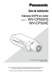
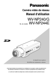
Installation Guide
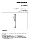
Color CCTV Camera
Model Nos.
WV-CP500
WV-CP504
This illustration represents WV-CP500.
Lens: Option
Before attempting to connect or operate this product, please read these
instructions carefully and save this manual for future use.
No model number suffix is shown in this manual.
WARNING:
• This apparatus must be earthed.
• Apparatus shall be connected to a mains socket outlet with a protective earthing connection.
• The mains plug or an appliance coupler shall
remain readily operable.
• To prevent fire or electric shock hazard, do not
expose this apparatus to rain or moisture.
• The apparatus should not be exposed to dripping or splashing and that no objects filled with
liquids, such as vases, should be placed on the
apparatus.
• All work related to the installation of this product should be made by qualified service personnel or system installers.
• The connections should comply with local electrical code.
For Canada
This Class A digital apparatus complies with
Canadian ICES-003.
CAUTION
For U.S.A
RISK OF ELECTRIC
SHOCK DO NOT OPEN
NOTE: This equipment has been tested and
found to comply with the limits for a Class A digital
device, pursuant to Part 15 of the FCC Rules.
These limits are designed to provide reasonable
protection against harmful interference when the
equipment is operated in a commercial environment. This equipment generates, uses, and can
radiate radio frequency energy and, if not
installed and used in accordance with the instruction manual, may cause harmful interference to
radio communications.
Operation of this equipment in a residential area
is likely to cause harmful interference in which
case the user will be required to correct the interference at his own expense.
CAUTION: TO REDUCE THE RISK OF ELECTRIC SHOCK,
DO NOT REMOVE COVER (OR BACK).
NO USER-SERVICEABLE PARTS INSIDE.
REFER SERVICING TO QUALIFIED SERVICE PERSONNEL.
The lightning flash with arrowhead symbol, within an equilateral triangle, is intended to alert
the user to the presence of uninsulated "dangerous voltage"
within the product's enclosure
that may be of sufficient magnitude to constitute a risk of electric shock to persons.
FCC Caution: To assure continued compliance,
(example - use only shielded interface cables
when connecting to computer or peripheral devices). Any changes or modifications not expressly
approved by the party responsible for compliance
could void the user’s authority to operate this
equipment.
The exclamation point within an
equilateral triangle is intended to
alert the user to the presence of
important operating and maintenance (servicing) instructions in
the literature accompanying the
appliance.
Power disconnection. Unit with or without ON-OFF
switches have power supplied to the unit whenever
the power cord is inserted into the power source;
however, the unit is operational only when the ONOFF switch is in the ON position. Unplug the power
cord to disconnect the main power for all units.
2
For U.S.A
The model number and serial number of this
product may be found on the surface of the unit.
You should note the model number and serial
number of this unit in the space provided and
retain this book as a permanent record of your
purchase to aid identification in the event of
theft.
Model No.
Serial No.
Important safety instructions
1) Read these instructions.
2) Keep these instructions.
3) Heed all warnings.
4) Follow all instructions.
5) Do not use this apparatus near water.
6) Clean only with dry cloth.
7) Do not block any ventilation openings. Install in accordance with the manufacturer's
instructions.
8) Do not install near any heat sources such as radiators, heat registers, stoves, or other
apparatus (including amplifiers) that produce heat.
9) Do not defeat the safety purpose of the polarized or grounding-type plug. A polarized plug
has two blades with one wider than the other. A grounding type plug has two blades and a
third grounding prong. The wide blade or the third prong are provided for your safety. If the
provided plug does not fit into your outlet, consult an electrician for replacement of the
obsolete outlet.
10) Protect the power cord from being walked on or pinched particularly at plugs, convenience
receptacles, and the point where they exit from the apparatus.
11) Only use attachments/accessories specified by the manufacturer.
12) Use only with the cart, stand, tripod, bracket, or table specified by the manufacturer, or
sold with the apparatus. When a cart is used, use caution when moving the cart/apparatus
combination to avoid injury from tip-over.
S3125A
13) Unplug this apparatus during lightning storms or when unused for long periods of time.
14) Refer all servicing to qualified service personnel. Servicing is required when the apparatus
has been damaged in any way, such as power-supply cord or plug is damaged, liquid has
been spilled or objects have fallen into the apparatus, the apparatus has been exposed to
rain or moisture, does not operate normally, or has been dropped.
3
Limitation of liability
THIS PUBLICATION IS PROVIDED "AS IS"
WITHOUT WARRANTY OF ANY KIND,
EITHER EXPRESS OR IMPLIED, INCLUDING
BUT NOT LIMITED TO, THE IMPLIED
WARRANTIES OF MERCHANTABILITY,
FITNESS FOR ANY PARTICULAR PURPOSE,
OR NON-INFRINGEMENT OF THE THIRD
PARTY'S RIGHT.
THIS PUBLICATION COULD INCLUDE
TECHNICAL INACCURACIES OR
TYPOGRAPHICAL ERRORS. CHANGES ARE
ADDED TO THE INFORMATION HEREIN, AT
ANY TIME, FOR THE IMPROVEMENTS OF
T H I S P U B L I C AT I O N A N D / O R T H E
CORRESPONDING PRODUCT (S).
Disclaimer of warranty
IN NO EVENT SHALL Panasonic Corporation
B E L I A B L E T O A N Y PA R T Y O R A N Y
PERSON, EXCEPT FOR REPLACEMENT OR
REASONABLE MAINTENANCE OF THE
PRODUCT, FOR THE CASES, INCLUDING
BUT NOT LIMITED TO BELOW:
(1) ANY DAMAGE AND LOSS, INCLUDING
WITHOUT LIMITATION, DIRECT OR
INDIRECT, SPECIAL, CONSEQUENTIAL
OR EXEMPLARY, ARISING OUT OF OR
RELATING TO THE PRODUCT;
(2) PERSONAL INJURY OR ANY DAMAGE
CAUSED BY INAPPROPRIATE USE OR
NEGLIGENT OPERATION OF THE USER;
(3) U N A U T H O R I Z E D D I S A S S E M B L E ,
REPAIR OR MODIFICATION OF THE
PRODUCT BY THE USER;
(4) INCONVENIENCE OR ANY LOSS ARISING WHEN IMAGES ARE NOT DISPLAYED, DUE TO ANY REASON OR
CAUSE INCLUDING ANY FAILURE OR
PROBLEM OF THE PRODUCT;
4
(5) ANY PROBLEM, CONSEQUENTIAL
INCONVENIENCE, OR LOSS OR DAMAGE, ARISING OUT OF THE SYSTEM
COMBINED BY THE DEVICES OF THIRD
PARTY.
Preface
This product is a 1/3-inch type {1/3"} CCD color CCTV camera. Connection of this product to a
video monitor allows users to use this product as a monitoring camera.
• WV-CP500: 120 V AC power supply
• WV-CP504: 24 V AC, 12 V DC power supply
Introduction of SUPER-D5 (super dynamic function)
Integration of SUPER-D5 into the CCD and signal processing circuit has achieved approximately 128 times higher dynamic range as compared with conventional camera. Thanks to the integration of the darkness compensation function, a subject on which much illuminance difference
exists resulting from bright and dark areas can be naturally displayed in an image.
Introduction of newly developed high-resolution CCD
The introduction of the newly developed CCD with 976 of horizontal pixels has led to the horizontal resolution of as high as 650 TV lines (typ.).
Auto back focus function (ABF) equipped
Moving the CCD inside the camera to an optimal position with the operation button of this unit
or the setup menu allows users to automatically adjust the back focus.
The back focus is adjustable with the setup menu through the system controller (option) even
after installation of this unit.
The auto back focus function also allows users to correct out of focus when changing between
color and black-and-white images.
High sensitivity achieved thanks to noise reduction function
Minimum illumination 0.3 lx (F1.4) has been accomplished for color images thanks to the introduction of low noise circuit design.
Night monochrome image activation function equipped
No operation is required at night because the image automatically changes from the color
mode to the black-and-white mode at low illuminance.
Intelligent VMD (i-VMD) functions of motion detection and object abandonment/removal
detection equipped
The motion and abandonment/removal of an object are detectable.
The states of covering the camera with a cloth, a cap or others and changing the camera direction notably can be detected (interference detection).
The detection resolution has been significantly improved as compared with a conventional
type, and the introduction of the newly developed detection method has improved detection
accuracy under the condition that the motion detection is prone to malfunction due to leaves
swaying.
Note:
• The i-VMD function is not the dedicated function to prevent thefts, fires, etc. We are not
responsible for any accidents or damages occurring in case.
5
About the user manuals
The operating instructions of the camera consist of 2 sets: this book and operating instructions
(PDF).
This book explains how to install the camera.
Refer to the "Operating Instructions (PDF)" on the provided CD-ROM for descriptions of how to
perform the unit settings. Adobe® Reader® is required to read PDF. When the Adobe® Reader®
is not installed on the PC, download the latest Adobe® Reader® from the Adobe web site and
install it.
Trademarks and registered trademarks
Adobe and Reader are either registered trademarks or trademarks of Adobe Systems
Incorporated in the United States and/or other countries.
6
Contents
Important safety instructions.......................................................................................................
Limitation of liability.....................................................................................................................
Disclaimer of warranty.................................................................................................................
Preface........................................................................................................................................
About the user manuals..............................................................................................................
Trademarks and registered trademarks......................................................................................
Precautions.................................................................................................................................
Major operating controls and their functions...............................................................................
Precautions for installation..........................................................................................................
Installation and connection..........................................................................................................
Optional dedicated lens..........................................................................................................
External synchronization switch.............................................................................................
Setup menu.................................................................................................................................
List of setup menu.....................................................................................................................
Basic operation.........................................................................................................................
Screen transition diagram.........................................................................................................
Troubleshooting...........................................................................................................................
Specifications..............................................................................................................................
Standard accessories..................................................................................................................
3
4
4
5
6
6
8
9
12
14
14
18
22
22
24
26
27
29
30
7
Precautions
This product has no power switch.
Power is supplied from an external 12 V DC/
24 V AC (WV-CP504) or 120 V AC (WVCP500) power-supply device. Refer to service personnel for how to turn on/off the
power.
Use this product for indoor use only.
Do not expose this product to direct sunlight
for hours and do not install the product near
a heater or an air conditioner. Otherwise, it
may cause deformation, discoloration and
malfunction. Keep this product away from
water.
To keep on using with stable performance
• Parts of this product may deteriorate and
it may shorten lifetime of this product
when using in locations subject to high
temperatures and high humidity. Do not
expose this product to direct heat sources such as a heater.
• Use this product at temperatures within
–10 °C to +50 °C {14 °F to 122 °F}, and
humidity below 90 % (when using this
product without turning the power off).
Do not rub the edges of metal parts with
your hand.
Failure to observe this may cause injury.
not use strong abrasive detergent when
cleaning this product. When the dirt is hard
to remove, use a mild detergent and wipe
gently. Then, wipe off the remaining detergent with a dry cloth.
Otherwise, it may cause discoloration. When
using a chemical cloth for cleaning, read the
caution provided with the chemical cloth
product.
Noise on monitor
This product is equipped with a super sensitive CCD. Therefore, white dot noise may
appear on the monitor. This phenomenon is
not trouble.
Discoloration on the CCD color filter
When continuously shooting a bright light
source such as a spotlight, the color filter of
the CCD may have deteriorated and it may
cause discoloration. Even when changing the
fixed shooting direction after continuously
shooting a spotlight for a certain period, the
discoloration may remain.
Do not aim this product at strong light
sources.
A light source such as a spot light causes a
blooming (light bleeding) or a smear (vertical
lines).
Smear
Do not attempt to disassemble this product.
To prevent electric shock, do not remove
screws or covers.
There are no user-serviceable parts inside.
Ask qualified service personnel for servicing.
Handle this product with care.
Do not abuse this product. Avoid striking,
shaking, etc. The product could be damaged
by improper handling or storage.
Cleaning this product body
Turn the power off when cleaning the product. Use a dry cloth to clean this product. Do
8
Bright subject
Blooming
Turn the circuit breaker off which supplies
this product with the power when abnormal conditions are encountered.
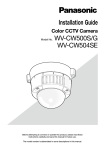
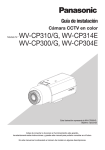
Major operating controls and their functions
Side view (WV-CP500)
ALC lens connector
Side cover
Tripod mount base
Inside the side cover
(Slide the cover leftward to the lock position.)
(UP)
NEAR
BF/MENU
(LEFT)
(SET)
FAR
(RIGHT)
(DOWN)
Operation buttons*
* The following names are assigned to
each button in this book:
: Up button (UP)
: Down button (DOWN)
: Left button (LEFT), NEAR
: Right button (RIGHT), FAR
: Setting button (SET), BF/MENU
Side view (WV-CP504)
ALC lens connector
Tripod mount base
9
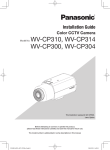
Rear view (WV-CP500)
External terminal
ALARM OUT
GND
ALARM IN
Power indicator
Video output connector
POWER
VIDEO OUT
120V ~ 60Hz
Power connector
Rear view (WV-CP504)
External terminal
ALARM OUT
VIDEO OUT
GND
POWER
ALARM IN
Power indicator
(UP)
NEAR
24V ~ IN
1-L
2-N
(LEFT)
GND
BF/MENU
(SET)
FAR
(RIGHT)
(DOWN)
12V
IN
NC
AC/DC power terminal
Video output connector
10
Operation buttons*
* The following names are assigned to
each button in this book:
: Up button (UP)
: Down button (DOWN)
: Left button (LEFT), NEAR
: Right button (RIGHT), FAR
: Setting button (SET), BF/MENU
Side cover (only for WV-CP500)
When the operation buttons are used, the
side cover is slide leftward to the lock position.
Power indicator
This indicator lights up when the power is on.
ALC lens connector
The ALC connector is connected to this ALC
lens connector.
Power connector (only for WV-CP500)
The included power cord is connected to this
power connector.
Tripod mount base
This socket is used to mount the camera
mount bracket (option). The tripod socket
can be mounted on either top or bottom of
the camera head.
(Tripod socket hole: 1/4-20 UNC for tripod)
AC/DC power terminal
(only for WV-CP504)
The power supply of 24 V AC or 12 V DC is
connected to this terminal.
External terminal (☞ page 18)
Operation buttons
This buttons are used to perform various settings in the setup menu.
Video output connector
The Coaxial cable (locally procured) is connected to this video output connector.
11
Precautions for installation
This camera is designed to be used
indoors. This camera is not operable outdoors.
Do not operate this product beyond the
specified temperature, humidity or power
source ratings.
Use this product at temperatures within
–10 °C to +50 °C {14 °F to 122 °F}, and
humidity below 90 %.The input power source
is 12 V DC/24 V AC (WV-CP504) or 120 V AC
(WV-CP500).
Installing place
Contact your dealer for assistance if you are
unsure of an appropriate place in your particular environment.
• Make sure that the installation area is
strong enough to hold the camera, such
as a concrete ceiling.
• If a ceiling board such as plaster board
is too weak to support the total weight,
the area shall be sufficiently reinforced.
• Do not install this product in a humid or
dust-laden environment.
Otherwise, lifetime of the internal parts
may be shortened.
Avoid installing in the following locations.
• Locations where it may get wet from rain
or water splash
• Locations where a chemical agent is
used such as a swimming pool
• Locations subject to steam and oil smoke
such as a kitchen, Locations near flammable gas or vapor
• Locations where radiation or x-ray emissions are produced
• Locations subject to strong magnetic
field or radio waves
• Locations where corrosive gas is produced
• Locations where it may be damaged by
briny air such as seashores
• Locations where the temperature is not
within –10 °C to +50 °C {14 °F - 122 °F}.
12
• Locations subject to vibrations (This
product is not designed for on-vehicle
use.)
• Locations subject to condensation as the
result of severe changes in temperature
Avoid installing the camera in a place with
a high level of noise.
Installation near an air conditioner, an air
cleaner, a vending machine, or the like
causes noise.
Avoid connections during a lightning
storm.
Otherwise, an electric shock may be caused.
Be sure to remove this product if it is not
in use.
Keep the camera cable away from the
lighting cable.
Failure to observe this may cause noise.
Radio interference
When the camera is used near TV/radio
antenna, strong electric field or magnetic
field (near a motor or a transformer), images
may be distorted and noise sound may be
produced.
Mounting screws
• Screws are not supplied with this product.
• Prepare them according to the material
and strength of the area where the product is to be installed.
• Do not use an impact driver. Use of an
impact driver may damage the screws.
• The screws and bolts must be tightened
with an appropriate tightening torque
according to the material and strength of
the installation area.
Power cord (only for WV-CP500)
Connect the power cord securely. Run the
power cord so that no load is applied to the
cord when panning or tilting the camera.
(Failure to observe this may disconnect the
power cord, and accordingly no image is displayed.)
13
Installation and connection
Cautions:
• ONLY CONNECT WV-CP504 TO 24 V AC OR 12 V DC CLASS 2 POWER SUPPLY.
• Be sure to connect the grounding lead to the GND terminal.
z Rotate the lens (option) clockwise slowly to mount the lens.
Protrusion from mount:
ø20 mm {25/32”} or less
Important:
• For use of C-mount lens, use the C-mount adaptor (option).
• For prevention of damage to the camera body, use a lens with protrusion of 5.5 mm {7/32"}
or less from the flange surface.
Protrusion from flange:
5.5 mm {7/32"} or less
Optional dedicated lens
Lens type
ALC lens for 1/3 inch CCD cameras
Model Nos.
2x vari-focal
WV-LZA61/2S
WV-LZA62/2
14
8x vari-focal
WV-LZ62/8S
15x motorized zoom
WV-LZ61/15
x Connect the lens cable to the ALC lens connector of the camera.
1 3
ALC lens connector
2 4
Pin No.
1
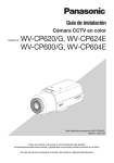
cSecure the camera mount bracket
(option) to an installation position, and
mount the camera on the camera mount
bracket.
Important:
• If the total weight of the camera and lens
exceeds 1 kg {2.2 lbs.}, use a housing to take
measures against camera drop.
• Prepare mounting screws according to the
material of the area where the camera mount
bracket (option) is to be installed. The installation method may be different depending on
the material of the area where the bracket is
to be installed.
• When installing on steel:
Fix with bolts and nuts (M6 or M8).
• When installing on concrete:
Fix with anchor bolts or AY plug bolts (M6
or M8).
Recommended tightening torque (M6):
5.0 N·m {3.69 lbf·ft}
Recommended tightening torque (M8):
6.2 N·m {4.57 lbf·ft}
2
3
4
Brake @
Brake !
Drive !
Drive @
<Installation sample on a ceiling>
Camera mount
bracket (option)
Screws (locally
procured)
Screws (locally
procured)
15
• The mounting conditions of the camera mount bracket are described as follows:
Installation
place
Applicable mount
bracket
Recommended
screw
Number of
screw
Minimum pull-out
strength (per 1 pc.)
On ceiling
WV-7011
M6
4 pcs.
196 N {44.06 lbf}
WV-7010
M8
3 pcs.
196 N {44.06 lbf}
WV-7012
M6
3 pcs.
196 N {44.06 lbf}
WV-831
M8
4 pcs.
921 N {207.05 lbf}
WV-7013
M6
3 pcs.
2.25 kN {505.82 lbf}
On wall
For some applicable mount brackets, "A" is attached to the model number. The mounting conditions are the same even for the A-attached models.
• When attaching an optional tripod mount
base on the bottom of the camera, use
the removed screws to attach the tripod
mount base. Use of longer or shorter
screws may cause drop or damage.
Recommended tightening torque:
0.39 N·m {0.29 lbf·ft}
Tripod socket
hole: 1/4-20
UNC for tripod
Tripod mount
base
Mounting
screws
16
v The video output cable is connected to this video output connector.
Important:
• Be sure to turn off the power of each device before connection.
• Be sure to secure the coaxial cable connectors.
Connect a coaxial cable to the video output connector.
ALARM OUT
GND
ALARM IN
Coaxial cables
POWER
To video input
VIDEO OUT
120V ~ 60Hz
WV-CP500
bUse a cable tie (locally procured) to attach the coaxial cable to the camera mount
bracket.
Important:
• The cable tie shall be made of metallic or durable material to be strong enough because
the tie plays the role of camera drop prevention measures in case.
• When the camera mount bracket is mounted on a wall, be sure to observe the mounting
height described on the illustration above.
<Installation sample on a ceiling>
<Installation sample on a wall>
Camera mount
bracket (option)
The cable shall be
tied to the camera
mount bracket to
avoid slack.
The cable shall be
tied to the camera
mount bracket to
avoid slack.
Camera mount
bracket (option)
More than
270 cm {8.9'}
Floor
17
External synchronization switch
The settings of the alarm input/output are configured on the SETUP menu.
Refer to the network operating instructions (PDF) for further information.
Important:
• Be sure to turn off the power of each device before connection.
Alarm output
Input specification: Open collector output (max. voltage: 16 V DC)
Off: Internally pulled up
2 V to 4 V DC
On: Output voltage 1 V DC or less (max.
drive current: 100 mA)
Functions: Alarm output
Black-and-white switching output
ALARM OUT
GND
ALARM IN
WV-CP500
POWER
VIDEO OUT
120V ~ 60Hz
ALARM OUT (Alarm output)
GND
ALARM IN (Alarm input)
Alarm input
Input specification: No-voltage make
contact input (3 to 5 V DC, internally
The external terminal is the same between
pulled up)
WV-CP500 and WV-CP504.
Off: Open or 3 to 5 V DC
On: Make contact with GND (required
drive current: 0.2 mA or more)
Functions: Alarm input
VMD enabling input
Color/BW switching input
Scene file switching input
* When an external device is connected, exercise care to avoid exceeding the rating.
* Applicable wire: 22 AWG-28 AWG, solidWV-CP500
wire/stranded wire
Strip the end 9 mm to 10 mm {11/32" to 13/32"} of the wire and
Stripped
insert it.
ALARM OUT
GND
ALARM IN
POWER
VIDEO OUT
9 mm - 10 mm
{11/32" to 13/32"}
120V ~ 60Hz
ALARM OUT (Alarm output)
GND
ALARM IN (Alarm input)
The external terminal is the same between
WV-CP500 and WV-CP504.
18
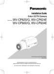
n Turn on the power.
WV-CP500
The included power cord is connected to this power connector.
Connect between the power connector on the rear side of the camera and a plug socket
with the supplied power cord.
ALARM OUT
GND
ALARM IN
POWER
Power cord (accessory)
VIDEO OUT
120 V AC 60 Hz
120V ~ 60Hz
WV-CP504
ALARM OUT
VIDEO OUT
GND
POWER
ALARM IN
2-N
GND
1-L
DC 12 V
@ (GND)
NC
!
IN
(SET)
FAR
(RIGHT)
NC
To 24 V AC/12 V DC
power supply
A
<Ratings>
AC 24 V
BF/MENU
(DOWN)
12V
B
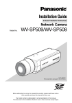
q Loosen the screw of the power cord plug
(accessory).
w Connect the power supply (option) of 24 V
AC or 12 V DC to the power cord plug.
Strip the end of the wire by 3 mm to 7 mm
{1/8" to 1/4"}, and twist the stripped part of
the wire sufficiently to avoid short circuit.
• Specification of cable (wire)
AWG #16 - #28, Single core, twisted
* Check whether the stripped part of the
wire is not exposed and is securely connected.
(UP)
NEAR
24V ~ IN
1-L
2-N
(LEFT)
GND
C
Important:
• The power supply of 24 V AC/12 V DC shall
be insulated against 120 V AC.
• The power supply is automatically selected
either 24 V AC or 12 V DC. No setting is
required with this camera.
Power cord plug
(accessory)
Stripped
Approx. 3 mm - 7 mm
e Tighten the screw of the power cord plug.
{1/8" to 1/4"}
r Connect the power cord plug to the AC/DC
power terminal on the rear side of the camera.
* Make sure that the power cord plug is inserted fully into the AC/DC power supply terminal.
19
mAdjust the camera angle by loosening the screw of the camera mount bracket
while viewing the video monitor.
Be sure to loosen the screw of the camera mount bracket when the camera angle is adjusted. If the camera angle is changed when the screw is tight, excessive force is applied to
the camera mount bracket and camera, and accordingly they may be damaged. Be sure to
tighten the screw securely after camera angle adjustment.
, Adjust the focus.
To use the varifocal lens/zoom lens
• Reset the back focus position to the CS mount default position before the back focus
adjustment (Press the right and left buttons simultaneously for more than 2 seconds, or
move the cursor to "MANUAL-ADJ" of "BACK-FOCUS" in the setup menu and press the
right and left buttons simultaneously for more than 2 seconds after pressing the setting button.).
• Be aware that the adjustment method varies with varifocal lens or zoom lens models. For
further information, refer to the operating instructions for the lens.
• The adjustment procedure for general varifocal lenses is described as follows: For further
information, refer to the operating instructions for the lens to be used.
q Display a subject that exists as far as possible to adjust the back focus (10 m {33'} or
more recommended).
w For 8-, or 10-fold magnification lenses, adjust the back focus (+ See below) after setting the zoom to the WIDE end and setting the focus to the FAR end.
For 2-, or 3-fold magnification lenses, adjust the back focus (+ See below) after setting
the zoom to the TELE end and setting the focus to the FAR end.
e Adjust the view angle and focus coarsely by adjusting the zoom and focus of the lens
to center a subject in the screen, and then perform the main adjustment of the back
focus (+ See below).
To use a fixed-focal lens
• For a fixed focus lens with focus adjustment, adjust the back focus (+ See below) after setting the focus of the lens to the FAR end.
How to adjust the back focus
Use the operation buttons (+ pages 12 and 13) for this adjustment.
The back focus is also adjustable in the setup menu. Refer to the operating instructions
(PDF) for further information.
q Press the setting button after adjusting the view angle while viewing the video monitor.
w The focus position indicator is displayed in the lower part of the screen, and the back
focus is automatically adjusted.
NEAR
FAR
.........|..........
INDICATOR XXXX FOCUSING
20
e To perform fine adjustment of the back focus after automatic back focus adjustment,
use the right or left button. (No operation for 10 seconds or more closes the setup
menu.)
Note:
• When an auto iris lens is used to record a subject, the originally adjusted focus may be
slightly off depending on the iris state resulting from the focal depth of the lens. In such a
case, open the aperture by darkening the subject as much as possible in the same way of
taking picture, and then adjust the focus. Defocus can be prevented.
• For adjustment according to "How to adjust the back focus", the focus can automatically be
adjusted under the optimal follow-up conditions even though the illuminance changes
(Note: The adjusted focal point is not necessarily the same as the optimal focal point at a
certain illuminance.).
• The out-of-focus level in the near-infrared light region may be higher than that in the visible
light region.
Setting "C/L ← → B/W" of "BACK-FOCUS SETUP" to "AUTO" or "PRESET" in the setup menu
(+ the setup instructions (PDF) allows users to adjust the focus in both the near-infrared
light and visible light regions (The variation in illuminance is not followed after focus adjustment.).
• When a non-Panasonic lens that has an extended range for lens focusing is used, adjust
the back focus after setting the focus to a position at a short distance from the FAR end. If
adjustment is performed in the extended range, appropriate adjustment
21
Setup menu
Performing each setting item in the setup menu should be completed in advance to use this
unit. Perform the settings for each item in accordance with the conditions of the camera shooting area.
Refer to the operating instructions (PDF) for further information.
List of setup menu
Setup item
CAMERA ID
This item specifies the camera title. The camera title that indicates
the camera location and other information about the camera is created with alphanumeric characters and symbol, and displayed on
the screen.
CAMERA
Performs the camera operation settings.
SCENE 1/SCENE 2
Selects a scene file. It is possible to register and save the settings
as a scene file in case that it is necessary to change the settings
such when shooting at night or on holidays.
ALC/ELC
Selects the method of controlling the quantity of light in accordance
with the lens to be used.
SHUTTER
Specifies the electronic shutter speed.
AGC
Specifies gain adjustment.
SENS UP
Specifies electronic sensitivity enhancement.
WHITE BAL
Specifies white balance adjustment.
DNR
Selects the level of the digital noise reduction function.
BW MODE
Performs each setting regarding the black-and-white mode such as
switching between color and black-and-white images.
i-VMD
Performs settings regarding intelligent VMD (Video Motion Detector)
such as motion detection and object abandonment/removal detection.
SYSTEM
Performs the settings regarding the camera system such as synchronization, alarm input/output, and privacy zone.
SYNC
Specifies the synchronization type.
ALARM IN/OUT
Performs the settings of the ALARM IN connector and the ALARM
OUT connector.
PRIVACY ZONE
Hides undesired portions in the camera shooting area.
STABILIZER
Decides whether or not to enable the image stabilizer.
EL-ZOOM
Toggles the electronic zoom on and off.
BACK-FOCUS
22
Description
Selects the back focus setting type and performs fine adjustment.
Setup item
Description
SPECIAL
CHROMA GAIN
Adjusts the chroma level.
AP GAIN
Adjusts the aperture level.
PEDESTAL
Adjusts the pedestal (brightness) level.
HUE
Adjusts the chroma phase (hue).
PIX OFF
Corrects image defects such as flaws.
COMMUNICATION
Performs the communication setting of the system with a receiver
into which this unit is integrated.
CAMERA RESET
Restores the settings in the setup menu to the default settings.
SER.NO.
Displays the serial number of this unit.
LANGUAGE
Selects a language to be used in the setup menu.
23
Basic operation
The description below explains how to operate the setup menu basically.
The operations in the setup menu are performed with the operation buttons (☞ pages 9 and
10) after calling up the setup menu on the connected video monitor.
The operations in the setup menu can also be performed through the system controller (option).
Screenshot 1
Hold down the setting button for approx. 2
seconds to call up the top screen of the
setup menu.
MODEL
WV-CP500 SERIES
CAMERA ID
OFF
CAMERA
SYSTEM
BACK-FOCUS
SPECIAL
LANGUAGE
END
SETUP DISABLE
Step 1
Press the up button or the down button to
move the cursor to "END".
Step 2
Press the right button to move the cursor to
"SETUP", and press the setting button to
change the setup mode from "DISABLE" to
"ENABLE".
Screenshot 2
The setup mode changes to "ENABLE", and
the setup menu becomes ready to be set.
MODEL
WV-CP500 SERIES
CAMERA ID
OFF
CAMERA
SYSTEM
BACK-FOCUS
SPECIAL
LANGUAGE
END
24
SETUP ENABLE
Step 3
Move the cursor to the item to be set, and
press the setting button.
Screenshot 3
The selected setup screen in the setup menu
appears on the screen.
**CAMERA SETUP**
SCENE1
ALC/ELC
ALC
SHUTTER
OFF
AGC
ON(HIGH)
SENS UP
OFF
WHITE BAL
ATW1
DNR
HIGH
BW MODE
AUTO1
i-VMD
RET TOP END
Note:
• If the top screen of the setup menu is
called up with the operation buttons
while a camera image is displayed, the
setup mode is always "DISABLE" to prevent operation errors.
To perform settings in the setup menu,
change the setup mode to "ENABLE".
• The cursor is a reversely highlighted
part.
Step 4
Perform the settings for each item.
• Selection of setting item:
Press the up button or down button to
move the cursor.
• Change of settings:
Press the right button or left button.
• Display of advanced setup screen:
Press the setting button when "O" is
attached to the target setting item.
• Return to previous setup screen:
Move the cursor to "RET" and press the
setting button.
• Return to the top screen:
Move the cursor to "TOP" and press the
setting button.
Step 5
To return to the camera image screen, move
the cursor to "END" and press the setting button.
25
Screen transition diagram
Top screen
MODEL
WV-CP500 SERIES
CAMERA ID
OFF
CAMERA
SYSTEM
BACK-FOCUS
SPECIAL
LANGUAGE
END
SETUP ENABLE
"CAMERA ID" screen
**CAMERA ID**
0123456789
ABCDEFGHIJKLM
NOPQRSTUVWXYZ
().,'":;&#!?=
+-*/%$
SPACE POSI
RET TOP END RESET
................
"CAMERA SETUP" screen
**CAMERA SETUP**
SCENE1
ALC/ELC
ALC
SHUTTER
OFF
AGC
ON(HIGH)
SENS UP
OFF
WHITE BAL
ATW1
DNR
HIGH
BW MODE
AUTO1
i-VMD
RET TOP END
"SYSTEM SETUP" screen
**SYSTEM SETUP**
SYNC
INT
ALARM IN/OUT
PRIVACY ZONE
STABILIZER
EL-ZOOM
OFF
OFF
OFF
RET TOP END
"BACK-FOCUS SETUP" screen
**BACK-FOCUS SETUP**
ABF
PUSH SW
MANUAL-ADJ
C/L
B/W
AUTO
SETUP-SW LOCK OFF
NEAR
FAR
.........|.........
INDICATOR XXXX
RET TOP END
"SPECIAL SETUP" screen
**SPECIAL SETUP**
...|...128
CHROMA GAIN
...|... 32
AP GAIN
...|... 32
PEDESTAL
...|... 0
HUE
+
PIX OFF
COMMUNICATION COAX
CAMERA RESET PUSH SW
SER.NO. XXXXXXXX
RET TOP END
"LANGUAGE SETUP" screen
**LANGUAGE SETUP**
LANGUAGE
SET
RET TOP END
26
ENGLISH
Troubleshooting
Before asking for repairs, check the symptoms with the following table.
Contact your dealer if a problem cannot be solved even after checking and trying the solution
in the table or a problem is not described below.
Symptom
No image displayed
Cause/solution
Reference
pages
•Are the power cord and coaxial cable
connected appropriately?
→ Check whether the connection is
appropriately established. 17, 19
•Is the monitor brightness appropriately
adjusted, or is the contrast appropriately adjusted?
→ Check whether the monitor settings
are appropriate. –
•Is the lens cap detached?
→ Check whether the lens cap is
removed. –
• Is the lens of the camera soiled with
dirt or dust?
→ Check whether the lens of the
camera is clean. –
•Is the focus adjusted correctly?
→ Check if the focus is adjusted correctly. 20 - 21
Blurred image
27
Inspect the power cord, power plug and power connectors periodically.
Symptom
Cause/solution
Reference
pages
•The power cord, power connector, or
power plug is damaged.
Use of the damaged cord, connector,
or plug may cause electric shock or
fire.
Disconnect the power plug immediately and request repair to your dealer.
–
Damaged power cord
sheathing
Heated portion of power
line consisting of power
cord, connector, and
power plug during use
Warmed power cord or
loosened connection by
bending or stretching
during use
28
Specifications
• General
Power source:
WV-CP500: 120 V AC 60 Hz
WV-CP504: 24 V AC 60 Hz, 12 V DC
Power consumption:
WV-CP500: 3.2 W
WV-CP504: 24 V AC: 3.6 W, 12 V DC: 310 mA
Ambient operating temperature: –10 °C to +50 °C {14 °F to 122 °F}
Ambient operating humidity:
Less than 90 % (non condensing)
Video output:
VBS: 1.0 V [p-p]/75 Ω, NTSC, BNC connector
External I/O terminals:
Alarm input, VMD enabling input, Color/BW switching input,
Scene file switching input, Alarm output, Black-and-white
switching output
Dimensions:
WV-CP500: 75 (W) x 65 (H) x 132.5 (D) mm
{2-15/16" (W) x 2-9/16" (H) x 5-7/32" (D)}
(Connectors and terminals excluded)
WV-CP504: 7
2 (W) x 65 (H) x 103.5 (D) mm
{2-27/32" (W) x 2-9/16" (H) x 4-1/16" (D)}
(Connectors and terminals excluded)
Weight:
WV-CP500: Approx. 430g {0.95 lbs} (Power cord excluded)
WV-CP504: Approx. 350g {0.77 lbs}
Finish:
Light FL silver
• Camera
Image sensor:
Effective pixels:
Scanning area:
Scanning system:
Scanning frequency:
Synchronization:
Resolution:
Minimum illumination:
Signal-to-noise ratio:
Dynamic range:
ALC lens drive:
Lens mount:
1/3 inch interline transfer CCD
976 (H) x 494 (V)
4.8 mm (H) × 3.6 mm (V)
2:1 interlace
Horizontal: 15.734 kHz
Vertical: 59.94 Hz
Internal (INT), multiplexed vertical drive (VD2) or line-lock (LL)*
* Phase adjustable
Horizontal: 6
50 TV lines typ. (color mode)
700 TV lines or more (BW mode)
Vertical: 350 TV lines or more (at center)
Color mode: 0.3 lx {0.03 footcandle}
(sensitivity up OFF, AGC HIGH: F1.4)
0.01 lx {0.001 footcandle}
(sensitivity up 32x, AGC HIGH: F1.4)*
BW mode: 0.04 lx {0.004 footcandle}
(sensitivity up OFF, AGC HIGH: F1.4)
0.0015 lx {0.00015 footcandle}
(sensitivity up 32x, AGC HIGH: F1.4)*
* Converted value
50 dB (AGC OFF)
52 dB typ. (Super Dynamic 5 ON)
DC drive
CS-mount
29
Functions:
Camera title:
Light control mode setting:
Super Dynamic 5
Electronic shutter speed:
AGC:
Sensitivity up:
White balance:
Digital noise reduction:
Color/BW:
Intelligent VMD (i-VMD):
Number of scene file:
Privacy zone:
Image stabilizer:
Electronic zoom:
Auto back focus:
Display language:
Up to 16 characters (alphanumeric characters, marks)
ALC/ALC+/ELC
ON/ON (i-VMD)/OFF
OFF (1/60), 1/100, 1/250, 1/500, 1/1000, 1/2000, 1/4000,
1/10000 s
ON (HIGH, MID, LOW)/OFF
OFF/AUTO (×2, ×4, ×6, ×10, ×16, ×32)/FIX (×2, ×4, ×6, ×10,
×16, ×32)
ATW1/ATW2/AWC
HIGH/LOW
AUTO1/AUTO2/ON/OFF
Video Motion Detection
Object Detection (Removal and Left Behind)
Scene Change Detection
2
ON (1)/ON (2)/OFF
ON/OFF
ON (up to 2x)/OFF
ABF/MANUAL/switching between color and BW interlocking
JAPANESE/ENGLISH/FRANÇAIS/ESPAÑOL/DEUTSCH/
ITALIANO/êìëëäàâ
Standard accessories
CD-ROM* ....................................................... 1 pc.
Operating Instructions (this book) . ................ 1 pc.
Warranty card ................................................. 1 pc.
*The CD-ROM contains the operating instructions (PDF).
The following parts are used during installation procedures.
Power connector (only for WV-CP500)............ 1 pc.
Power cord plug (only for WV-CP504) ........... 1 pc.
30
31
Panasonic System Solutions Company,
Unit Company of Panasonic Corporation of North America
www.panasonic.com/business/
For customer support, call 1.800.528.6747
Three Panasonic Way 2H-2, Secaucus,
New Jersey 07094
Panasonic Canada Inc.
5770 Ambler Drive, Mississauga, Ontario, L4W 2T3 Canada
(905)624-5010
http://www.panasonic.ca
Panasonic Sales Company
Panasonic Puerto Rico, Inc.
AVE 65de Inf, Km 9.5 Carolina, PR 00985
(787)750-4300
© Panasonic Corporation 2009
Ns0409-0/1
3TR005978AZA
Printed in China