1
IP Proprietary Telephone
Model No.
KX-NT400
Thank you for purchasing an IP Proprietary Telephone (IP-PT).
Please read this manual carefully before using this product and save this manual for future use.
For more details, please refer to the manuals of the PBX.
SD Logo is
a trademark.
Document Version 2010-01
Introduction
Introduction
Feature Highlights
Color LCD Touch Screen
Call handling
Call logs
Contacts
Chat
The large, color LCD touch screen provides a simple interface for operating the KX-NT400. You can assign
commonly used phone numbers and functions to flexible keys for easy access. You can also check messages,
missed calls, and more simply by pressing buttons on the screen. The touch screen also provides an intuitive
interface for managing contacts and call logs.
2
Operating Instructions
Document Version 2010-01
Introduction
Interact Efficiently with Other Users
The KX-NT400 provides features that support interacting and working efficiently with other users. The following
are examples of these features.
• Set a presence status, such as "Available" or "In Conference", that can be viewed by other users.
• View the state of other users’ telephones.
• Establish a text chat session with other users.
Network Camera Integration
The KX-NT400 can display video feeds from Panasonic Network Cameras (e.g., KX-HCM/BB-HCM/BL-C
series). You can register up to 20 cameras. If a registered camera is connected to a doorphone, whenever you
make a call to or receive a call from that doorphone, the video feed is automatically displayed on the
KX-NT400. In addition, you can register camera information with a contact, and view the camera’s video feed
when talking to the contact.
Document Version 2010-01
Operating Instructions
3
Introduction
Portal
You can view intranet Web pages on the KX-NT400 via the portal (Web browser). This can be useful for
accessing resources such as company news or an employee directory. You can also make calls directly from
an intranet Web page that contains links to telephone numbers.
Data Import and Export to SD Memory Card
The KX-NT400 contains an SD memory card slot so that you can back up the KX-NT400’s data to an SD
memory card. You can back up information such as your personal contacts, chat log, and settings. If you switch
phones or data is lost from the KX-NT400, you can recover your data from the SD memory card.
4
Operating Instructions
Document Version 2010-01
Introduction
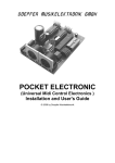
System Diagram
The figure below illustrates an example network setup using the KX-NT400.
1
2
3
4
5
7
6
8
4
9
LAN
Other Connections
Panasonic KX-NCP Series PBX
Voice Processing System
Panasonic Network Camera
Panasonic KX-NT400
Doorphone and Door Opener
Proprietary Telephone or Single Line Telephone
PC Running CA Client
Web Server
Portable Station
IMPORTANT
•
If a PC that has Communication Assistant (CA) installed is connected to the KX-NT400, do not set the
extension number in CA to the same extension number that is assigned to the KX-NT400.
Document Version 2010-01
Operating Instructions
5
Introduction
Notice
•
6
When a portable station is configured to share an extension number with the KX-NT400, to apply the
configuration you must restart the KX-NT400.
Operating Instructions
Document Version 2010-01
Introduction
Other Information
Included Documentation
Operating Instructions (this document)
Describes how to connect, use, program, and maintain the unit.
Note
•
The contents and design of the software are subject to change without notice.
Trademarks
•
•
The Bluetooth® word mark and logos are owned by the Bluetooth SIG, Inc. and any use of such marks by
Panasonic Corporation is under license.
All other trademarks identified herein are the property of their respective owners.
MPEG-4 Visual License
•
This product is licensed under the MPEG-4 Visual patent portfolio license for the personal and
non-commercial use of a consumer for (i) encoding video in compliance with the MPEG-4 Visual Standard
("MPEG-4 Video") and/or (ii) decoding MPEG-4 Video that was encoded by a consumer engaged in a
personal and non-commercial activity and/or was obtained from a video provider licensed by MPEG LA to
provide MPEG-4 Video. No license is granted or shall be implied for any other use. Additional information
including that relating to promotional, internal, and commercial uses and licensing may be obtained from
MPEG LA, LLC. See http://www.mpegla.com.
JPEG License
•
The software of this product is based in part on the work of the Independent JPEG Group.
Fugue License
•
This unit uses the "Fugue" flash file system by Kyoto Software Research Corporation. Fugue © 1999 2008 Kyoto Software Research, Inc. All rights reserved. You may not modify, decompile, disassemble, or
reverse engineer the software.
Firmware Notice
•
The firmware of the KX-NT400 is protected by copyright laws and international treaty provisions, and all
other applicable laws. It can not be reverse engineered, decompiled, or disassembled.
Document Version 2010-01
Operating Instructions
7
Introduction
For Future Reference
Record the information in the space below for future reference.
Note
•
The serial number of this product may be found on the label affixed to the side of the unit. You should
note the serial number of this unit in the space provided and retain this manual as a permanent record
of your purchase to aid in identification in the event of theft.
MODEL NO.
SERIAL NO.
DATE OF PURCHASE
NAME OF DEALER
DEALER'S ADDRESS
DEALER'S TEL. NO.
8
Operating Instructions
Document Version 2010-01
For Your Safety
For Your Safety
To reduce the risk of injury, loss of life, electric shock,
fire, malfunction, and damage to equipment or property,
always observe the following safety precautions.
Explanation of symbols
The following symbols are used to classify and describe
the level of hazard and injury caused when the
denotation is disregarded and improper use is
performed.
WARNING
Denotes a potential hazard that could result in
serious injury or death.
CAUTION
Denotes a hazard that could result in minor injury or
damage to the unit or other equipment.
WARNING
General Safety
Do not disassemble this unit. Dangerous
electrical shock could result. The unit must
only be disassembled and repaired by
qualified service technicians.
Never attempt to insert wires, pins, etc. into
the vents or other holes of this unit.
To prevent possible fire or electric shock, do
not expose this unit to rain or moisture.
If damage to the unit exposes any internal
parts, immediately disconnect the cable or
cord. If the power is supplied from the network
to the IP-PT [Power-over-Ethernet],
disconnect the Ethernet cable. Otherwise,
disconnect the AC adaptor cord. Then return
this unit to a service center.
This handset earpiece is magnetized and may
retain small ferrous objects.
The following symbols are used to classify and describe
the type of instructions to be observed.
The use of excessive sound volume through
earphone, headphones, or headsets may
cause hearing loss.
This symbol is used to alert users to a specific
operating procedure that must not be
performed.
Disconnect this unit from power outlet/the
Ethernet cable if it emits smoke, an abnormal
smell, or makes unusual noise. These
conditions can cause fire or electric shock.
Confirm that smoke has stopped and contact
an authorized service center.
Installation
This symbol is used to alert users to a specific
operating procedure that must be followed in
order to operate the unit safely.
Do not use this unit near water, for example,
near a bathtub, washbowl or sink. Damp
basements should also be avoided.
The unit should only be connected to a power
supply of the type described in the Operating
Instructions or as shown on the label on the
unit.
Placement
Care should be taken so that objects do not
fall onto, and liquids are not spilled into, the
unit. Do not subject this unit to excessive
smoke, dust, moisture, mechanical vibration,
shock, or direct sunlight.
Do not place heavy objects on top of this unit.
Document Version 2010-01
Operating Instructions
9
For Your Safety
Place this unit on a flat surface.
•
Use only the correct Panasonic handset.
Allow 10 cm (3 15/16 in) clearance around the
unit for proper ventilation.
CAUTION
Keep the unit away from heating appliances
and devices that generate electrical noise,
such as fluorescent lamps, motors and
televisions. These noise sources can interfere
with the performance of the unit. It also should
not be placed in rooms where the temperature
is less than 5 °C (41 °F) or greater than 40 °C
(104 °F).
Do not press or rub the LCD touch screen with
too much force. A light touch is enough for the
LCD touch screen to respond.
Wipe the unit with a soft cloth. Do not clean
the unit with abrasive powders or with
chemical agents such as benzene or thinner.
The SD memory card and the handset hook
pose a choking hazard. Keep the SD memory
card and the handset hook out of reach of
children.
When left unused for a long period of time,
disconnect the unit from the AC outlet. When
the unit receives power from a PoE power
supply, disconnect the LAN cable.
Notice
•
•
•
•
10
If the unit does not operate properly, disconnect
the AC adaptor cord and LAN cable and then
connect again.
If you are having problems making calls,
disconnect the Ethernet cable and connect a
known working IP-PT. If the known working
IP-PT operates properly, have the defective
IP-PT repaired by an authorized Panasonic
factory service center. If the known working
IP-PT does not operate properly, check the PBX
and the Ethernet cable.
Under power failure conditions, the IP-PT may
not operate. Please ensure that a separate
telephone, not dependent on local power, is
available for use in remote sites in case of
emergency.
If an error message is shown on the unit’s
display, consult the network administrator.
Operating Instructions
Document Version 2010-01
For Your Safety
Data Security
We recommend observing the security precautions
described in this section, in order to prevent the
following:
– loss, disclosure, falsification, or theft of user
information
– unauthorized use of the unit
– interference or suspension of use caused by an
unauthorized party
We cannot be responsible for damages resulting
from the misuse of this product.
User information is defined as the following:
– Contacts’ names, phone numbers, and IP
addresses
– Call logs
Preventing Data Loss
•
•
Keep a copy of all important data (such as contact
lists) in case the machine malfunctions and data
cannot be recovered.
Use a personal computer to make periodic backups
of recordings stored on the SD memory card.
Preventing Data Disclosure
•
•
•
•
•
•
•
Do not leave the unit or SD memory card in a
location where it can be accessed or removed
without authorization.
Store backups in a secure location.
Do not store sensitive personal information in the
unit.
In the following situations, initialize the unit (see
"Data Maintenance" on page 166), and remove the
SD memory card from the unit.
– Before disposing of the unit
– Before handing the unit over to a third party
– Before having the unit serviced
Make sure the unit is serviced by only a certified
technician.
The confidentiality of the information on the SD
memory card becomes the responsibility of the
customer. To prevent data leakage, render the SD
Memory Card physically unusable before disposal.
When user information is sent from the KX-NT400
to a PC or other external device, the confidentiality
of that information becomes the responsibility of the
customer. Before disposing of the PC or other
external device, ensure that data cannot be
Document Version 2010-01
retrieved from it by formatting the hard disk and/or
rendering it physically unusable.
Preventing Data Disclosure Over the
Network
•
•
•
To ensure the security of private conversations,
only connect the unit to a secure network.
To prevent unauthorized access, only connect the
unit to a network that is properly managed.
Make sure all personal computers that are
connected to the unit employ up-to-date security
measures.
For Bluetooth® Headset
Users
Medical:
Consult the manufacturer of any personal medical
devices, such as pacemakers or hearing aids, to
determine if they are adequately shielded from external
RF (radio frequency) energy (the product operates in
the frequency range of 2.4000 GHz to 2.4835 GHz and
the power output is 2.5 mW [max.]). Do not use the
product in health care facilities if any regulations posted
in the area instruct you not to do so. Hospitals or health
care facilities may be using equipment that could be
sensitive to external RF energy.
Operating Instructions
11
Additional Information
Additional Information
Important Safety Instructions
When using this unit, basic safety precautions,
including those below, should always be followed to
reduce the risk of fire, electric shock and injury to
persons.
1. Read and understand all instructions.
2. Follow all warnings and instructions marked on this
unit.
3. Unplug this unit from the AC outlet before cleaning.
Do not use liquid or aerosol cleaners. Clean with a
damp cloth.
4. Do not use the unit near water, for example, near a
bathtub, kitchen sink, or laundry tub, in a wet
basement, or near a swimming pool.
5. Place this unit on a flat surface. Serious damage
and/or injury may result if the unit falls.
6. The unit should never be placed near or over a
radiator or other heat source.
7. This unit should be operated only from the type of
power source indicated on the unit label. If you are
not sure of the type of power supply to your home,
consult your dealer or local power company.
8. Do not allow anything to rest on the power cord. Do
not locate this unit where the cord may be stepped
on or tripped on.
9. To reduce the risk of fire or electric shock, do not
overload AC outlets and extension cords.
10. Do not insert objects of any kind into this unit
through openings, as they may touch dangerous
voltage points or short out parts that could result in
a risk of fire or electric shock. Never spill liquid of
any kind on the unit.
11. To reduce the risk of electric shock, do not
disassemble this unit. Only qualified personnel
should service this unit. Opening or removing
covers may expose you to dangerous voltages or
other risks. Incorrect reassembly can cause electric
shock.
12. Unplug this unit from the AC outlet and have the unit
serviced by qualified service personnel in the
following cases:
A. When the power supply cord or plug is damaged
or frayed.
B. If liquid has been spilled on the unit.
C. If the unit has been exposed to rain or water.
D. If the unit does not work normally by following
the manual. Adjust only controls covered by the
manual. Improper adjustment may require
repair by an authorized service center.
12
Operating Instructions
E. If the unit has been dropped, or damaged.
F. If the unit’s performance deteriorates.
13. Avoid using a telephone (other than a cordless type)
during an electrical storm. There is a remote risk of
electric shock from lightning.
14. Do not use the telephone in the vicinity of a gas leak
to report the leak.
SAVE THESE INSTRUCTIONS
FCC and Other Information
This equipment has been tested and found to comply
with the limits for a Class B digital device, pursuant to
Part 15 of the FCC Rules. These limits are designed to
provide reasonable protection against harmful
interference in a residential installation. This equipment
generates, uses, and can radiate radio frequency
energy and, if not installed and used in accordance with
the instructions, may cause harmful interference to
radio communications. However, there is no guarantee
that interference will not occur in a particular installation.
If this equipment does cause harmful interference to
radio or television reception, which can be determined
by turning the equipment off and on, the user is
encouraged to try to correct the interference by one or
more of the following measures:
• Reorient or relocate the receiving antenna.
• Increase the separation between the equipment
and receiver.
• Connect the equipment into an outlet on a circuit
different from that to which the receiver is
connected.
• Consult the dealer or an experienced radio/TV
technician for help.
CAUTION
Any changes or modifications not expressly
approved by the party responsible for compliance
could void the user’s authority to operate this
device.
FCC Declaration of Conformity
Trade Name: Panasonic
Model Number: KX-NT400
Responsible Party:
Panasonic Corporation of North America
One Panasonic Way
Secaucus, NJ 07094 U.S.A.
Telephone No.: 1-800-211-PANA (7262)
This device complies with Part 15 of the FCC Rules.
Document Version 2010-01
Additional Information
Operation is subject to the following two conditions:
(1) This device may not cause harmful interference, and
(2) this device must accept any interference received,
including interference that may cause undesired
operation.
This equipment complies with Part 68 of the FCC rules
and the requirements adopted by the ACTA. On the
bottom of the cabinet of this equipment is a label that
contains, among other information, the following
product identifier:
US:ACJKXNANKX-NT400
If requested, this number must be provided to the
telephone company.
If this equipment causes harm to the telephone network,
the telephone company will notify you in advance that
temporary discontinuance of service may be required.
But if advance notice isn't practical, the telephone
company will notify the customer as soon as possible.
Also, you will be advised of your right to file a complaint
with the FCC if you believe it is necessary.
The telephone company may make changes in its
facilities, equipment, operations or procedures that
could affect the operation of the equipment. If this
happens the telephone company will provide advance
notice in order for you to make necessary modifications
to maintain uninterrupted service.
If trouble is experienced with this equipment, for repair
or warranty information, please contact:
Panasonic Service and Technology Company-BTS
Center
415 Horizon Drive Bldg. 300 Ste. 350-B
Suwanee, GA 30024-3186
WHEN PROGRAMMING EMERGENCY NUMBERS
AND (OR) MAKING TEST CALLS TO EMERGENCY
NUMBERS:
a. Remain on the line and briefly explain to the
dispatcher the reason for the call.
b. Perform such activities in the off-peak hours, such
as early morning or late evenings.
This equipment is hearing aid compatible.
This unit features a Bluetooth Module slot that can
be used to wirelessly connect a Bluetooth headset
to the unit.
Radio Frequency Exposure Requirements
(When an optional Bluetooth Module is installed)
This product complies with FCC radiation exposure
limits set forth for an uncontrolled environment. To
comply with FCC RF exposure requirements, it must be
installed and operated in accordance with provided
instructions. The unit requires minimum 20 cm (8 in)
spacing must be provided between antennas and all
person’s body (excluding extremities of hands, wrists
and feet) during wireless modes of operation. This
transmitter must not be colocated or operated in
conjunction with any other antenna or transmitter.
Compliance with TIA-1083 standard
Compatible with
Hearing Aid T-Coil
Telephone handsets identified with
this logo have reduced noise and
interference when used with T-Coil
equipped hearing aids and cochlear
implants.
T
TIA-1083
If the equipment is causing harm to the telephone
network, the telephone company may request that you
disconnect the equipment until the problem is resolved.
Connection to party line service is subject to state tariffs.
Contact the state public utility commission, public
service commission or corporation commission for
information.
If your home has specially wired alarm equipment
connected to the telephone line, ensure the installation
of this equipment does not disable your alarm
equipment. If you have questions about what will
disable alarm equipment, consult your telephone
company or a qualified installer.
Document Version 2010-01
Operating Instructions
13
Table of Contents
Table of Contents
Before Operating the Telephone ..........................................................17
Accessory Information ...................................................................................................17
Location of Controls .......................................................................................................18
Operation Board Angle Adjustment ..............................................................................23
Hooking the Handset ......................................................................................................25
Screens & Soft Buttons ..................................................................................................27
Navigation ......................................................................................................................27
HOME Screen ................................................................................................................29
Contacts Screen .............................................................................................................32
Calls Screen ...................................................................................................................37
Calls Screen in Line Buttons Mode .............................................................................37
Calls Screen in Call List Mode .....................................................................................40
Call Log Screen ..............................................................................................................47
Camera Screen ..............................................................................................................49
Chat Screen ...................................................................................................................52
Portal Screen ..................................................................................................................54
Feature Key Screen .......................................................................................................55
Options Screen ...............................................................................................................57
Basic Operations .............................................................................................................58
Confirming Your Extension Number ...............................................................................58
Going off- and on-hook ...................................................................................................58
Adjusting the Volume .....................................................................................................58
Basic Screen Operations ................................................................................................59
Entering Text ..................................................................................................................60
Basic Feature Operation ........................................................................62
Making Calls ....................................................................................................................62
Making a Call ..................................................................................................................62
Making a Call from the Contact List ...............................................................................63
Dialing by Using Call Logs .............................................................................................65
Redialing the Last Number You Dialed (Redial, Last Number) ......................................66
One-touch Dialing ...........................................................................................................66
Receiving Calls ................................................................................................................67
Receiving a Call .............................................................................................................67
Redirecting Calls ............................................................................................................68
During a Conversation ....................................................................................................69
Holding a Call .................................................................................................................69
Receiving a Second Call (Answering Call Waiting) ........................................................70
Talking to Two Parties Alternately (Call Splitting) ..........................................................71
Transferring a Call (Call Transfer) ..................................................................................71
Mute ...............................................................................................................................72
Recording Calls (Two-way Recording) ...........................................................................72
Conference Call (Multiple Party Conversation) ............................................................73
Making a Conference Call ..............................................................................................73
Removing a Participant from the Conference ................................................................74
Leaving a Conference (Unattended Conference) ...........................................................74
Locking Operations (Application Lock) ........................................................................75
Checking Messages ........................................................................................................76
Checking New Messages ...............................................................................................76
Accessing Voice Mail .....................................................................................................77
Checking Missed Calls ...................................................................................................78
Presence Status Setting .................................................................................................78
14
Operating Instructions
Document Version 2010-01
Table of Contents
Call Forwarding/Do Not Disturb .....................................................................................79
Advanced Feature Operation ................................................................81
Network Camera ..............................................................................................................81
Selecting Cameras to View ............................................................................................81
Zooming In and Out ........................................................................................................81
Adjusting the Angle of the Camera .................................................................................82
Opening Doors ...............................................................................................................82
Full-Screen Mode ...........................................................................................................82
Chat ..................................................................................................................................83
Making a Call to a Chat Participant ................................................................................83
Portal (Web Browser) ......................................................................................................84
Selecting a URL to Access .............................................................................................84
Going Back to Your Homepage ......................................................................................84
Making Calls from the Portal ..........................................................................................84
Other Feature Operations ......................................................................86
When the Dialed Line is Busy or There is No Answer .................................................86
Sending a Call Waiting Notification (Call Waiting) ..........................................................86
Leaving a Message Waiting Indication ...........................................................................86
Leaving a Voice Message ..............................................................................................86
Reserving a Busy Line (Automatic Callback Busy) ........................................................87
Joining an Existing Conversation (Executive Busy Override) ........................................87
Overriding Do Not Disturb (DND Override) ....................................................................87
If a Host PBX is Connected ............................................................................................88
Accessing External Services (External Feature Access [EFA]) .....................................88
PBX Feature List ....................................................................................89
Customizing the Telephone ................................................................108
Contact List ...................................................................................................................108
Adding a New Contact ..................................................................................................108
Adding a Contact from a Call Log ................................................................................108
Adding a Contact from the PBX ...................................................................................109
Adding a Contact from an LDAP Directory ...................................................................109
Editing a Contact ..........................................................................................................109
Deleting a Contact ........................................................................................................109
Details for Contacts ......................................................................................................109
User Options ..................................................................................................................113
Password Settings ........................................................................................................113
Display Settings ............................................................................................................113
Dial Number Settings ...................................................................................................114
Language Settings .......................................................................................................115
Directory List Select Settings .......................................................................................115
IP Camera Settings ......................................................................................................116
IP Camera Selection Buttons Settings .........................................................................117
Portal Settings ..............................................................................................................117
Presence Settings ........................................................................................................118
Administrator Options ..................................................................................................121
LDAP Server Settings ..................................................................................................121
Dial Modification Settings .............................................................................................122
PT Programming ...........................................................................................................125
Customizing the Flexible Buttons ...............................................................................133
Entering Characters .....................................................................................................145
Document Version 2010-01
Operating Instructions
15
Table of Contents
Installation and Settings ......................................................................147
Connections ..................................................................................................................147
Wall Mounting ................................................................................................................150
Bluetooth Headset Connections ..................................................................................153
Installation ....................................................................................................................153
Bluetooth Headset Operation .......................................................................................155
Setting Up the KX-NT400 ..............................................................................................157
Accessing the Start-up Settings ...................................................................................157
Language Settings .......................................................................................................159
IP Address Settings ......................................................................................................159
IP Port Settings ............................................................................................................160
Quality of Service (QoS) Settings .................................................................................161
Maintenance .................................................................................................................162
Firmware Version Update .............................................................................................163
Setting Initialize ............................................................................................................165
Firmware Version .........................................................................................................165
Error Log ......................................................................................................................166
Maintaining the KX-NT400 ............................................................................................166
Data Maintenance ........................................................................................................166
Initializing the KX-NT400 ..............................................................................................168
Restarting the KX-NT400 .............................................................................................168
Cleaning the KX-NT400 ...............................................................................................169
Appendix ...............................................................................................170
Specifications ................................................................................................................170
Programming Items ......................................................................................................171
User Options ................................................................................................................171
Administrator Options ...................................................................................................176
Firmware Version Update ..........................................................................................180
SD Memory Cards .........................................................................................................181
Important Information ...................................................................................................181
Compatible SD Memory Cards .....................................................................................181
Inserting and Removing SD Memory Cards .................................................................181
Write Protection (LOCK) ...............................................................................................181
Formatting SD Memory Cards ......................................................................................182
Troubleshooting ............................................................................................................183
Common Issues and Solutions .....................................................................................183
Error Messages ............................................................................................................192
Error Codes ..................................................................................................................193
Index............................................................................................................197
16
Operating Instructions
Document Version 2010-01
Before Operating the Telephone
Before Operating the Telephone
Accessory Information
Included Accessories
*1
*1
Handset (1)
Handset Cord (1)
Stylus Pen (1)
Wall Mounting Adaptor (1)
Screws for Adaptor (2)
Screws and Washers for Wall (3 each)
For extra orders for the accessories, call toll-free: 1-800-332-5368.
Optional Accessories
AC Adaptor
KX-A420 (PSLP1662)
Bluetooth Module
KX-NT307 (PSLP1528)
Headset
KX-TCA86/KX-TCA92
Document Version 2010-01
Operating Instructions
17
Before Operating the Telephone
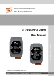
Location of Controls
Front View
A
B
C
D
E
F
J
G
H
I
LCD (Liquid Crystal Display)
Message/Ringer Lamp
When you receive an intercom call, the lamp flashes green, and on an outside call, the lamp flashes red.
When someone has left you a message, the lamp stays on red.
SP-PHONE (Speakerphone)
Used for performing hands-free operations. When the SP-PHONE is used, the lamp next to the SP-PHONE
button turns red.
HOLD
Used to put a call on hold.
TRANSFER
Used to transfer a call to another party.
CANCEL
Used to cancel the selected item.
MIC
Used for hands-free conversation.
Navigator Key
Used to adjust the volume or select desired items.
ENTER
Used to assign the selected item.
Handset Hook
Keeps the handset stable when the KX-NT400 is mounted on a wall. For details, see "To Lock the Handset
Hook when the KX-NT400 is Wall Mounted (Page 25)".
18
Operating Instructions
Document Version 2010-01
Before Operating the Telephone
Right Side View
A
B
C
Side Cover
SD Memory Card Slot
Used to insert an SD memory card. SD memory cards are used to backup and restore personal settings
and data. For details, see "SD Memory Cards (Page 181)".
USB Port
Used to connect a USB keyboard.
Document Version 2010-01
Operating Instructions
19
Before Operating the Telephone
Left Side View
A
B
C
D
Handset
Handset Jack
Headset Jack
Handset Cord
For details, see "Connections (Page 147)".
20
Operating Instructions
Document Version 2010-01
Before Operating the Telephone
Back View
A
B
C
D
Stylus Pen
Used to press buttons on the LCD.
Back Cover
Bluetooth Module Socket
For details, see "Bluetooth Headset Connections (Page 153)".
Operation Board Angle Adjust Button
Used to adjust the angle of the operation board.
For details, see "Operation Board Angle Adjustment (Page 23)".
Document Version 2010-01
Operating Instructions
21
Before Operating the Telephone
Bottom View
LAN Port
PC Port
DC Jack
For details, see "Connections (Page 147)".
22
Operating Instructions
Document Version 2010-01
Before Operating the Telephone
Operation Board Angle Adjustment
The angle of the operation board can be set to one of seven angles (level 1 = 30°, level 7 = 60°).
IMPORTANT
•
When you use the KX-NT400 first time, before adjusting the angle of the operation board, press and
hold the angle adjustment button, lift the operation board until you hear the lock click, and then release
the button.
CAUTION
•
•
•
Hold the operation board until it is secured at the desired angle.
Make sure you do not pinch your fingers when raising or lowering the operation board.
Do not squeeze the LCD touch screen when adjusting the operation board; applying too much pressure
will damage the screen.
To raise:
1. Hold the base of the unit with one hand.
2. Gently lift the operation board one level at a time to the desired angle.
Document Version 2010-01
Operating Instructions
23
Before Operating the Telephone
To lower:
1. Hold down the button as shown in the illustration below.
2. Hold the base of the unit with one hand.
3. Slightly lift the operation board to disengage the lock.
4. While holding down the button, tilt the board to the desired angle and then release the button.
24
Operating Instructions
Document Version 2010-01
Before Operating the Telephone
Hooking the Handset
You can hook the handset with following operations.
To Hook the Handset During a Conversation
1. Hook the handset over the top edge of the unit.
To Lock the Handset Hook when the KX-NT400 is Wall Mounted
1. Remove the handset hook from the slot.
2. Turn it up-side-down.
3. Slide the handset hook back into the slot until it locks.
Document Version 2010-01
Operating Instructions
25
Before Operating the Telephone
4. Handset is safely hooked when it is in the cradle.
26
Operating Instructions
Document Version 2010-01
Before Operating the Telephone
Screens & Soft Buttons
This section explains all of the buttons and icons that appear on each of the screens.
Navigation
You can navigate among the various screens on the KX-NT400 by using the tabs along the top screen.
A
Navigation details
A Tabs and controls
Description
Soft Button or Icon
/
Display the HOME screen (Page 29).
If the Calls screen is set to Line Buttons mode (the default
mode), an orange line appears on this tab when you have
new missed calls.
•
•
Checking Missed Calls (Page 78)
Calls Screen (Page 37)
Display the Contacts screen (Page 32).
Display the Calls screen (Page 37).
Display the Call Log screen (Page 47).
Document Version 2010-01
Operating Instructions
27
Before Operating the Telephone
Soft Button or Icon
Description
Display the Camera screen (Page 49).
Display the Chat screen (Page 52).
Display the Portal screen (Page 54).
Display the Options screen (Page 57).
/
28
Operating Instructions
Display additional tabs.
Document Version 2010-01
Before Operating the Telephone
HOME Screen
On the HOME screen, you can perform the following operations:
• Checking New Messages (Page 76)
• Checking Missed Calls (Page 78)
• Accessing Voice Mail (Page 77)
• Presence Status Setting (Page 78)
• Call Forwarding/Do Not Disturb (Page 79)
• Locking Operations (Application Lock) (Page 75)
• Auto answer (Page 67)
• Redialing the Last Number You Dialed (Redial, Last Number) (Page 66) (Call List mode only)
• Adjusting the Volume (Page 58)
The following screen shows the appearance of the HOME screen when the Calls screen is set to Line Buttons
mode.
A
B
If the Calls screen is set to Call List mode, additional buttons are displayed on the HOME screen.
C
Note
•
For details about the Calls screen’s modes, see "Calls Screen (Page 37)".
Document Version 2010-01
Operating Instructions
29
Before Operating the Telephone
HOME Screen Details
A Presence and messages
Soft Button or Icon
Description
Change your presence status.
•
Presence Status Setting (Page 78)
Change your Call Forwarding settings and Do Not Disturb
(DND) settings.
•
Call Forwarding/Do Not Disturb (Page 79)
Access the Voice Mail service.
This button appears if you have set the voice mail
system’s extension number.
•
Accessing Voice Mail (Page 77)
Check new messages.
This button appears only when there is a new message.
•
Checking New Messages (Page 76)
Display the missed call log.
This button appears only when there is a new missed call.
•
Checking Missed Calls (Page 78)
Displays the current time.
Note
If the Calls screen is set to Call List mode, the date is
displayed beneath the clock. For details about the
Calls screen, see "Calls Screen (Page 37)".
30
Operating Instructions
Document Version 2010-01
Before Operating the Telephone
B Miscellaneous controls
Soft Button or Icon
Description
Lock/Unlock access to all screens except the HOME,
Calls, and Feature Key screens.
: Access to screens is locked.
: Access to screens is unlocked.
/
•
Locking Operations (Application Lock) (Page 75)
Turn on/off Auto Answer (receiving an incoming call in
hands-free mode).
: Auto Answer is turned on.
: Auto Answer is turned off.
/
•
Receiving a Call (Page 67)
Indicates the ringer status.
: The ringer is turned on.
: The ringer is turned off.
/
•
Adjusting the Volume (Page 58)
Indicates the Bluetooth connection status.
: Communicating with module
: Linking
: Talking/Playing the background music
/
/
When a Bluetooth Module is not installed, these icons do
not appear on the screen.
•
Bluetooth Headset Connections (Page 153)
C Buttons available in Call List mode
Description
Soft Button or Icon
Redial the last number you dialed.
•
Redialing the Last Number You Dialed (Redial, Last
Number) (Page 66)
Display the Feature Key screen (Page 55).
Document Version 2010-01
Operating Instructions
31
Before Operating the Telephone
Contacts Screen
On the Contacts screen, you can view and make calls to contacts in your local directory and contacts stored
on an LDAP directory.
The following operations are available on this screen:
• Making a Call from the Contact List (Page 63)
• Starting a Chat Session (Page 83)
• Adding a New Contact (Page 108)
• Editing a Contact (Page 109)
• Deleting a Contact (Page 109)
Local Directory
LDAP Directory
A
D
B
E
C
Contacts Screen Details
A Local directory operations
Description
Soft Button or Icon
Select Directory to display the contacts stored in the local
directory.
To switch to the LDAP directory, press the directory
selection list, and select LDAP Search.
•
Making a Call from the Local Directory (Page 63)
Add a new contact to your personal contacts.
•
•
Adding a New Contact (Page 108)
Adding a Contact from the PBX (Page 109)
Search the local directory for a contact.
•
32
Operating Instructions
Making a Call from the Local Directory (Page 63)
Document Version 2010-01
Before Operating the Telephone
B Contact list entries
Soft Button or Icon
Description
Shows the status of the contact’s telephone.
Also, you can make a call, start a chat, or edit the
information about the contact.
•
•
•
•
Making a Call from the Local Directory (Page 63)
Chat (Page 83)
Telephone status icons (Page 33)
Details for Contacts (Page 109)
Scroll the list on the screen.
Scroll to the top/bottom of the list on the screen.
Telephone status icons
The icons for each directory entry indicate the status of each extension’s telephone.
For extensions using KX-NT400
Icon
Phone Status
Presence Status (Absent Message)
Presence status not set (Available)
Idle
Presence status On or DND for internal call
Presence status not set (Available)
Busy
Presence status On or DND for internal call
Presence status not set (Available)
Ringing
Presence status On or DND for internal call
For extensions logged in to Communication Assistant (CA)
Icon
Phone Status
Absent Message
Absent message not set (Available)
Idle
Absent message On or DND for internal call
Automatic absent message is set or DND for internal call
Document Version 2010-01
Operating Instructions
33
Before Operating the Telephone
Icon
Phone Status
Absent Message
Absent message not set (Available)
Busy
Absent message On or DND for internal call
Automatic absent message is set or DND for internal call
Absent message not set (Available)
Ringing
Absent message On or DND for internal call
Automatic absent message is set or DND for internal call
No Icon
The line is not connected
Note
•
The status of CA users connected through CA Server is not displayed. For details, consult your
administrator.
For other extensions
Phone Status
Icon
Absent Message
Absent message not set (Available)
Idle
Busy
Absent message On or DND for internal call
Absent message not set (Available)
Absent message On or DND for internal call
Absent message not set (Available)
Ringing
No Icon
Absent message On or DND for internal call
The line is not connected
C Contact summary information
Description
Soft Button or Icon
/
Display/hide the soft keyboard.
: The soft keyboard is not displayed.
: The soft keyboard is displayed.
•
34
Operating Instructions
Using the Soft Keyboard (Page 60)
Document Version 2010-01
Before Operating the Telephone
Soft Button or Icon
Description
Switch the character table used for entering characters
with the dial keys.
•
Entering Characters (Page 145)
Shows information for the selected contact:
• Phone number
• Presence status
Display the Dial window for pre-dialing.
•
Making a Call (Page 62)
Disconnect the current call.
D LDAP directory operations
Description
Soft Button or Icon
Select LDAP Search to display a contact list stored in
LDAP servers.
To switch to the local directory, press the directory
selection list, and select Directory.
•
Making a Call from the LDAP Directory (Page 64)
Display the LDAP Server Select screen.
Search the LDAP directory for a contact.
•
Making a Call from the LDAP Directory (Page 64)
Display the Advanced screen, from which you can perform
an advanced search.
•
Document Version 2010-01
Making a Call from the LDAP Directory (Page 64)
Operating Instructions
35
Before Operating the Telephone
E LDAP contact list entries
Soft Button or Icon
Description
Shows the contact’s name and registered phone number.
Also, you can make a call to and display detailed
information for the selected contact.
•
•
36
Operating Instructions
Making a Call from the LDAP Directory (Page 64)
Adding a Contact from an LDAP Directory (Page 109)
Document Version 2010-01
Before Operating the Telephone
Calls Screen
When you start a conversation or you answer a call, the Calls screen appears.
On the Calls screen, you can use PBX call handling features.
There are 2 modes for operating the Calls screen:
• Line Buttons Mode
In this mode, the Calls screen is similar to a conventional IP proprietary telephone (IP-PT). This mode lets
you easily access flexible keys, which you can customize freely. This is the default mode.
See "Calls Screen in Line Buttons Mode (Page 37)".
• Call List Mode
In this mode, your active calls are displayed in a list, and the available functions are displayed as buttons.
See "Calls Screen in Call List Mode (Page 40)".
For details about changing the mode, see "Display Settings (Page 113)".
Calls Screen in Line Buttons Mode
Line Buttons mode lets you easily access flexible keys. You can customize the flexible keys to access frequently
used functions and destinations. For details, see "Customizing the Flexible Buttons (Page 133)".
Additionally, to use the Call Waiting Caller ID (Visual Caller ID) function, use Line Buttons mode.
A
B
C
D
Calls Screen in Line Buttons Mode Details
A Soft buttons
Soft Button or Icon
Description
Soft buttons.
Use these buttons for feature key operations.
The buttons change according to current operation.
Document Version 2010-01
Operating Instructions
37
Before Operating the Telephone
Soft Button or Icon
Description
Sub-display.
Displays messages related to the current operation.
B Feature key page selection
Description
Soft Button or Icon
Change the feature key page.
C Feature keys
Description
Soft Button or Icon
You can customize the flexible buttons by assigning
functions to them.
•
Customizing the Flexible Buttons (Page 133)
D Function buttons
Description
Soft Button or Icon
Used to leave a message waiting indication or call back the
party who left the message waiting indication.
When you have a message waiting indication, this
button’s light blinks red.
•
•
Checking Message Waiting (Page 76)
Leaving a Message Waiting Indication (Page 86)
Used to make or receive intercom calls.
When you have seized the intercom line, this button’s light
lights green.
Used to mute the microphone during a conversation.
When mute is active, this button’s light blinks red.
•
38
Operating Instructions
Mute (Page 72)
Document Version 2010-01
Before Operating the Telephone
Soft Button or Icon
Description
Used to disconnect the current call and make another call
without hanging up. You can also use this button to access
external features, if any are available.
•
Accessing External Services (External Feature Access
[EFA]) (Page 88)
Used to redial the last outside phone number that you
dialed.
•
Document Version 2010-01
Redialing the Last Number You Dialed (Redial, Last
Number) (Page 66)
Operating Instructions
39
Before Operating the Telephone
Calls Screen in Call List Mode
Call List mode displays a list of all calls that you are currently handling. Call handling functions that are available
for the currently selected call are displayed beneath the list. The buttons change depending on the status of
the selected call.
Note
•
To display the Calls screen in Call List mode, see "Display Settings (Page 113)".
A
B
Calls Screen in Call List Mode Details
A Current call display
Description
Soft Button or Icon
Display information about the current calls.
Each entry shows the following information:
• For Outgoing Calls
– Call status icon
– The dialed number or name when available
– Duration of call
• For Incoming Calls
– Call status icon
– Number of the caller (up to 16 digits) or name when
available
– Group name of the caller when available
– Duration of call
•
•
40
Operating Instructions
Call status icons (Page 41)
During a Conversation (Page 69)
Document Version 2010-01
Before Operating the Telephone
Soft Button or Icon
Description
Scroll the list on the screen.
Call status icons
Call Status
Icon
Off-hook
Outgoing call
Incoming call
Active call
Call on hold
Call in a conference call (Conference is established)
Busy
Do not disturb
Parked call
No valid call (Reorder tone is heard)
B Call operations
Note
•
The buttons in area B change according to the selected call. When there is no available operation for
the selected call, no buttons are displayed.
Common
Description
Soft Button or Icon
/
Display the next/previous page for available
operations.
Hang up the call.
Document Version 2010-01
Operating Instructions
41
Before Operating the Telephone
Soft Button or Icon
Description
Mute/unmute outgoing voice and sound.
: Outgoing voice and sound is muted.
: Outgoing voice and sound is not muted.
/
•
Mute (Page 72)
For outgoing calls
Description
Soft Button or Icon
Leave a notification that you called to the called
extension.
This button appears only for internal calls.
•
Leaving a Message Waiting Indication (Page 86)
Leave a message using the voice mail service.
This button appears only for internal calls.
•
Leaving a Voice Message (Page 86)
For incoming calls
Description
Soft Button or Icon
Answer the selected call.
Redirect the selected call to a preset extension.
•
Redirecting Calls (Page 68)
Redirect the selected call to your voice mailbox.
•
42
Operating Instructions
Redirecting Calls (Page 68)
Document Version 2010-01
Before Operating the Telephone
For active calls
Soft Button or Icon
Description
Record the current call to voice mail.
This feature requires a Panasonic Voice Processing
System.
•
Recording Calls (Two-way Recording) (Page 72)
Stop recording the current call.
•
Recording Calls (Two-way Recording) (Page 72)
Invite a third party and establish a conference call.
•
Conference Call (Multiple Party Conversation)
(Page 73)
Park the call in an idle parking zone.
•
Holding a Call in a System Parking Zone (Call Park)
(Page 70)
Park the call in a specified parking zone.
•
Holding a Call in a System Parking Zone (Call Park)
(Page 70)
Transfer the call.
•
Transferring a Call (Call Transfer) (Page 71)
Transfer the call to an extension’s voice mail.
•
Transferring a Call (Call Transfer) (Page 71)
Put the call on hold.
•
Document Version 2010-01
Holding a call at your extension (Call Hold)
(Page 69)
Operating Instructions
43
Before Operating the Telephone
Soft Button or Icon
Description
Use External Feature Access (EFA) to access special
features offered by a host PBX or a telephone
company.
•
Accessing External Services (External Feature
Access [EFA]) (Page 88)
Switch the call on hold and the current call.
•
Talking to Two Parties Alternately (Call Splitting)
(Page 71)
For calls on hold
Description
Soft Button or Icon
Retrieve the selected call on hold.
•
Holding a Call (Page 69)
For calls in a conference call
Description
Soft Button or Icon
Invite a third party and establish a conference call.
•
Making a Conference Call (Page 73)
Remove the selected participant from the conference.
•
44
Operating Instructions
Removing a Participant from the Conference
(Page 74)
Document Version 2010-01
Before Operating the Telephone
For busy calls
Soft Button or Icon
Description
You can receive a callback ringing notification from an
extension when it becomes available.
This button appears only for internal calls.
•
Reserving a Busy Line (Automatic Callback Busy)
(Page 87)
Send the called extension a call waiting signal.
This button appears only for internal calls.
•
Sending a Call Waiting Notification (Call Waiting)
(Page 86)
Leave a notification that you called at the called
extension.
This button appears only for internal calls.
•
Leaving a Message Waiting Indication (Page 86)
Override the selected call.
The call will shift to conference mode.
This button appears only for internal calls.
•
Joining an Existing Conversation (Executive Busy
Override) (Page 87)
For Do Not Disturb calls
Description
Soft Button or Icon
Override Do Not Disturb.
•
Document Version 2010-01
Overriding Do Not Disturb (DND Override)
(Page 87)
Operating Instructions
45
Before Operating the Telephone
For parked calls
Soft Button or Icon
Description
Retrieve the selected parked call.
•
46
Operating Instructions
Holding a Call in a System Parking Zone (Call Park)
(Page 70)
Document Version 2010-01
Before Operating the Telephone
Call Log Screen
On the Call Log screen, you can view a list of your outgoing, incoming, and missed calls.
The following operations are available on this screen:
• Dialing by Using Call Logs (Page 65)
• Adding a Contact from a Call Log (Page 108)
A
B
Call Log Screen Details
A Call log selection
Soft Button or Icon
Description
Display the Outgoing call log.
Display the Incoming call log.
Display the Missed call log.
Document Version 2010-01
Operating Instructions
47
Before Operating the Telephone
B Call log entries
Soft Button or Icon
Description
Display the status icon, caller’s name, and timestamp of
the call.
You can make a call, add the party to the local directory,
display the caller’s picture, and display detailed
information.
•
•
•
Call log icons (Page 48)
Dialing by Using Call Logs (Page 65)
Adding a Contact from a Call Log (Page 108)
Scroll the log list on the screen.
Scroll to the top/bottom of the log list on the screen.
Call log icons
Icon
48
Outgoing
Incoming
Outgoing Answered Call
Incoming Received Call
Outgoing Unanswered Call
Incoming Missed Call
Operating Instructions
Missed
Incoming Missed Call
Document Version 2010-01
Before Operating the Telephone
Camera Screen
On the Camera screen, you can perform operations related to cameras.
• Network Camera (Page 81)
A
B
C
Camera Screen Details
A Camera display
Description
Soft Button or Icon
Shows the selected camera’s video feed.
•
Document Version 2010-01
Adjusting the Angle of the Camera (Page 82)
Operating Instructions
49
Before Operating the Telephone
B Camera selection buttons
Soft Button or Icon
Description
Quick-access button for registered cameras.
The name you registered for the camera is displayed on
the button (e.g., "Back Door", "Front").
•
•
Selecting Cameras to View (Page 81)
IP Camera Settings (Page 116)
C Camera operation
Description
Soft Button or Icon
Select a camera to display.
•
•
Selecting Cameras to View (Page 81)
IP Camera Settings (Page 116)
Choose a preset viewing angle for the selected camera.
•
Adjusting the Angle of the Camera (Page 82)
Zoom in the view.
*1
•
Zooming In and Out (Page 81)
Zoom out the view.
*1
•
Zooming In and Out (Page 81)
Show/hide the pan and tilt buttons on the camera view.
*1
•
Adjusting the Angle of the Camera (Page 82)
Switch to full-screen mode.
*1
•
Full-Screen Mode (Page 82)
Pan-scan the view.
*1
•
50
Operating Instructions
Adjusting the Angle of the Camera (Page 82)
Document Version 2010-01
Before Operating the Telephone
Soft Button or Icon
Description
Tilt-scan the view.
*1
•
/
Adjusting the Angle of the Camera (Page 82)
Mute/unmute outgoing voice and sound from the
KX-NT400.
: Outgoing voice and sound is muted.
: Outgoing voice and sound is not muted.
•
Mute (Page 72)
During a conversation with a doorphone, open the door
connected to a doorphone camera.
•
*1
Opening Doors (Page 82)
Depending on the camera model, this operation might not be available, or it might not function due to security settings, etc.
Document Version 2010-01
Operating Instructions
51
Before Operating the Telephone
Chat Screen
On the Chat screen, you can participate in a chat session with another KX-NT400 user or Communication
Assistant user. You can start a chat session by selecting a contact on the Contacts screen.
The following operations are available on this screen:
• Chat (Page 83)
• Making a Call to a Chat Participant (Page 83)
A
B
Chat Screen Details
A Chat area
Description
Soft Button or Icon
Scroll the chat log on the screen.
B Chat controls
Description
Soft Button or Icon
/
Display/hide the soft keyboard.
: The soft keyboard is not displayed.
: The soft keyboard is displayed.
•
Using the Soft Keyboard (Page 60)
Shows the name or the extension number of the other chat
participant.
52
Operating Instructions
Document Version 2010-01
Before Operating the Telephone
Soft Button or Icon
Description
Send the message you typed in the message input box.
Clear the text in the message input box.
Make a call to the other chat participant.
End the chat.
The other chat participant will be disconnected.
Document Version 2010-01
Operating Instructions
53
Before Operating the Telephone
Portal Screen
On the Portal screen, you can browse Web pages on your organization’s intranet.
• Portal (Web Browser) (Page 84)
A
Portal Screen Details
A Portal screen controls
Description
Soft Button or Icon
Select an intranet Web page from the Web page list.
•
Selecting a URL to Access (Page 84)
Display your homepage.
•
/
Display/hide the soft keyboard.
: The soft keyboard is not displayed.
: The soft keyboard is displayed.
•
54
Operating Instructions
Going Back to Your Homepage (Page 84)
Using the Soft Keyboard (Page 60)
Document Version 2010-01
Before Operating the Telephone
Feature Key Screen
If the Calls screen is set to Call List mode, you can use the Feature Key screen to perform operations in the
same way as on a Proprietary Display Telephone. You can access PBX features that are unavailable elsewhere
on the KX-NT400.
You can assign phone numbers and PBX features to the flexible keys for easy access. See the following section
for details:
• Customizing the Flexible Buttons (Page 133)
A
B
C
Note
•
•
The Feature Key screen is accessed by pressing Feature on the HOME screen. For details about the
HOME screen, see "HOME Screen (Page 29)".
If the Calls screen is set to Line Buttons mode, you cannot access this screen. All of the functions
available on this screen can be performed on the Calls screen. For details, see "Calls Screen in Line
Buttons Mode (Page 37)".
Feature Key Screen Details
A Soft buttons
Soft Button or Icon
Description
Soft buttons.
Use these buttons for feature key operations.
The buttons change according to current operation.
Sub-display.
Displays messages related to the current operation.
Document Version 2010-01
Operating Instructions
55
Before Operating the Telephone
B Feature key page selection
Soft Button or Icon
Description
Change the feature key page.
C Feature keys
Description
Soft Button or Icon
You can customize the flexible buttons by assigning
functions to them.
•
Customizing the Flexible Buttons (Page 133)
Return to the HOME screen.
•
56
Operating Instructions
HOME Screen (Page 29)
Document Version 2010-01
Before Operating the Telephone
Options Screen
From the Options screen, you can access various settings for the KX-NT400.
The following operations are available on this screen:
• User Options (Page 113)
• Administrator Options (Page 121)
A
Options Screen Details
A Options screen details
Description
Soft Button or Icon
Shows the extension number and name registered for your
extension.
Display the User Options screen.
•
User Options (Page 113)
Display the Administrator Options screen.
•
Document Version 2010-01
Administrator Options (Page 121)
Operating Instructions
57
Before Operating the Telephone
Basic Operations
This section explains the basics of using the
KX-NT400.
Confirming Your Extension
Number
You can view the extension number and name
registered to the KX-NT400 on the Options screen.
• To display the Options screen, press the Options
tab.
Going on-hook
In this manual, when you see the phrase "go on-hook",
you can do any of the following:
• Replace the handset on its cradle.
• If you are in hands-free mode, press
(SP-PHONE).
Usage tips
•
Certain on-screen buttons, such as the Hang up
button on the Calls screen (in Call List mode),
perform the same function as going on-hook.
Hands-free Mode
In hands-free mode, you can talk and hear the other
party in a conversation without using the handset. This
mode is useful for performing other tasks during a
conversation, such as writing.
Enabling hands-free mode
For details about the Options screen, see "Options
Screen (Page 57)".
Going off- and on-hook
With the KX-NT400 there are several ways to go
off-hook and on-hook:
• Using the handset
• Using the
(SP-PHONE) button
•
Using on-screen controls
Going off-hook
In this manual, when you see the phrase "go off-hook",
you can do any of the following:
• Lift the handset off of its cradle.
• Press
(SP-PHONE) while the handset is on its
cradle. This enables hands-free mode.
Usage tips
•
58
Certain on-screen buttons, such as the Answer
button on the Call Alert window, function like the
(SP-PHONE) button.
Operating Instructions
You can enable hands-free mode in one of the following
ways:
• In stand-by mode (i.e., when you have no active
(SP-PHONE).
calls), press
•
•
During a conversation while using the handset,
press
(SP-PHONE), and return the handset to
its cradle.
Certain on-screen buttons, such as the Answer
button on the Calls screen (in Call List mode),
activate hands-free mode as well. These buttons
appear only when you have an incoming call.
Canceling hands-free mode
You can cancel hands-free operation simply by lifting
the handset off its cradle.
Adjusting the Volume
You can adjust the ringer, handset, and speaker volume
using (UP) and (DOWN) on the Navigator key.
Adjusting the ringer volume
In stand-by mode (i.e., when you do not have any active
calls), press (UP) and (DOWN) on the Navigator
key.
Document Version 2010-01
Before Operating the Telephone
Usage tips
•
When the ringer volume is turned all the way down,
is displayed on the HOME screen. For details,
see "HOME Screen (Page 29)".
Adjusting the handset/headset/
speaker volume
explicitly written. For example, "Use the Navigator
key to highlight …".
Scrolling Pages
If there is more information than can be displayed on 1
screen, you can scroll the screen. The arrow buttons
and an indicator of the current and total number of
pages are displayed on the right side of the screen.
Press (UP) and (DOWN) on the Navigator key
during a conversation when using the handset, a
headset, or when you are in hands-free mode.
Basic Screen Operations
This section explains the basic operations for using the
screen.
Selecting Items
On screens such as the Contacts screen or Call Log
screen, you can select items using the stylus pen or the
Navigator key.
In this manual, when you see a phrase such as "Select
the item" or "Press the contact", you can do either of the
following:
• Press the item on-screen using the stylus pen.
• Press (UP) and (DOWN) on the Navigator key
to highlight the desired item, and then pressing
You can scroll through the pages by pressing the
arrows.
The arrows have the following meanings:
Scroll to the previous or following
page, respectively.
Scroll to the first or last page in the list,
respectively.
(ENTER).
Some items, such as call control buttons, can only be
operated using the stylus pen. If you cannot select an
item using the Navigator key, use the stylus pen to
select it instead.
Usage tips
•
Highlighted items are displayed with a yellow
background:
•
Some operations require you to use the Navigator
key to highlight an item before performing an action
on it. In this manual, when you must use the
Navigator key to perform an operation, it will be
Document Version 2010-01
Other Common Screen Operations
The following common operations can also be
performed using either the on-screen controls or the
hardware buttons.
On screens that have an OK button
The following actions are equivalent:
• Pressing OK with the stylus pen.
Operating Instructions
59
Before Operating the Telephone
•
Pressing
(ENTER).
Window with soft keyboard
On screens that have a Cancel button
The following actions are equivalent:
• Pressing Cancel with the stylus pen.
• Pressing
(CANCEL).
You can enter text by pressing the keys on the screen.
When you are finished entering text, press OK on the
bottom of the window.
Press Cancel to close the soft keyboard window without
changing the original contents of the text field.
Usage tips
Entering Text
•
Some screens, such as the Contacts and Chat
screens, contain a soft keyboard button:
There are 3 ways to input text:
• Using the Soft Keyboard (Page 60)
• Using a USB Keyboard (Page 61)
• Using the Dial Keys (Page 61)
Usage tips
•
•
You can select text by dragging over it with the
stylus pen.
•
After you have selected text, the following
operations are available (with the keyboard
operation shown in brackets):
– Copy (Ctrl + C)
– Cut (Ctrl + X)
– Paste (Ctrl + V)
Using the Soft Keyboard
When you press a text field on the screen, a window
containing the soft keyboard appears.
•
Press
to display and hide the soft keyboard.
To use the Shift key, press Shift once, and then
press the desired key. The keys will then return to
their original characters. You do not need to hold
Shift down while pressing a key as you do on a
normal keyboard.
The Ctrl key can be used in the same manner.
To enter accented characters, press
on the
soft keyboard:
If you are using the dial keys to enter text, pressing
switches the character table and allows you to
enter additional characters. For details about
character tables, see "Entering Characters
(Page 145)".
Note
•
60
Operating Instructions
The language for the soft keyboard depends on
the display language selected for the
KX-NT400. For details, see "Language Settings
(Page 115)".
Document Version 2010-01
Before Operating the Telephone
Using a USB Keyboard
If you connect a compatible USB keyboard*1 to the
KX-NT400, you can enter text with the USB keyboard
instead of the soft keyboard.
You can connect the keyboard at any time.
*1
User supplied.
Note
•
•
The USB port is located on the right side of the
KX-NT400. See "Right Side View (Page 19)".
For details about connecting a USB key board,
see "Connections for a USB Device
(Page 149)".
Using the Dial Keys
You can use the dial keys to enter text as well as
numbers. See "Entering Characters (Page 145)".
Document Version 2010-01
Operating Instructions
61
Basic Feature Operation
Basic Feature
Operation
, and then enter the phone number. When
you finish dialing, go off-hook or press
to connect the call.
Calling an Outside Party
Making Calls
You have to seize a CO line before dialing an outside
phone number. The KX-NT400 can seize a CO line
automatically for certain calls.
This section explains the basic methods for making a
call.
Automatic seizing
The number you are dialing is displayed in the
Dial window. When you finish dialing, the call will
be connected.
3. To end the call, go on-hook.
The KX-NT400 can seize a CO line automatically when
a call is made with one of the following operations:
• Pre-dialing (Page 62)
• Making a Call from the Contact List (Page 63)
• Dialing by Using Call Logs (Page 65)
• Redialing the Last Number You Dialed (Redial, Last
Number) (Page 66)
• One-touch Dialing (Page 66)
• Making Calls from the Portal (Page 84)
Pre-dialing
Manual seizing
In stand-by mode (i.e., when you have no active calls),
you can start dialing while still on-hook. The Dial
window will appear.
• To delete a number you entered, press (LEFT).
• To clear the entire number, press
(TRANSFER) or
(HOLD).
You have to seize a CO line manually when you directly
enter a phone number with dial keys.
1. Go off-hook.
or an L-CO button.
2. Press
An idle CO line will be seized.
3. Enter a phone number with dial keys.
Making a Call
1. In stand-by mode (i.e., when you have no active
calls), go off-hook.
2. Enter the number you want to call.
•
To connect the call, go off-hook or press
.
Note
Quick Dialing
•
If a number has been programmed in the PBX as a
Quick Dial number, you can dial that number by going
off-hook and entering the programmed number.
For details, consult your administrator.
Usage tips
Hot Line
•
You can configure the phone to automatically dial a
number immediately when you go off-hook. See "Hot
Line (Page 100)".
Operator Call
You can call an extension or a group assigned as the
operator. See "Operator Call (Page 102)".
Usage tips
•
After you dial, the Calls screen appears. For details,
see "Calls Screen (Page 37)".
•
You can create an L-CO button on the
KX-NT400. For details, see "Customizing the
Flexible Buttons (Page 133)".
To seize a specific CO line, in step 2 press the
corresponding CO button on the Calls screen or on
the Feature Key screen (in Call List mode). For
details about these screens, see "Calls Screen in
Line Buttons Mode (Page 37)" and "Feature Key
Screen (Page 55)".
To select an idle CO line in a specific CO line group
automatically, press a G-CO button, or press
and the CO line group number.
For details about creating a G-CO button, see
"Customizing the Flexible Buttons (Page 133)".
Note
•
62
If you want to dial a phone number on the
Contacts screen using the dial keys, press
Operating Instructions
Document Version 2010-01
Basic Feature Operation
Making a Call from the Contact
List
The KX-NT400 provides the following 2 types of contact
lists:
• Local Directory
The local directory contains the following types of
contacts:
– Your personal contacts
– System speed dialing directory contacts
– Extension number directory contacts
For details about adding personal contacts, see
"Contact List (Page 108)".
•
•
The characters you enter are displayed in
.
• You can enter up to 3 characters to search
for.
• You can delete a character by pressing
(LEFT) on the Navigator key.
4. Select the contact you want to call.
A window with a list of available destinations
appears.
5. Select the desired destination and go off-hook.
Destination selection for a personal contact
LDAP Directory
If you have configured the settings for an LDAP
server, you can view the contacts stored on that
server.
For details about configuring LDAP server settings,
see "LDAP Server Settings (Page 121)".
Note
•
When you display the Contacts tab, the
previously selected directory is displayed. The
first time you display the Contacts tab, the local
directory is displayed.
Destination selection for a contact from the
system speed dialing directory or extension
directory
Making a Call from the Local
Directory
1. Press the Contacts tab.
2. If necessary, press the directory selection list and
select Directory.
Note
•
You can start a chat session by pressing
Start Chat. For details, see "Chat
(Page 83)".
6. To end the call, go on-hook.
Usage tips
•
3. To search for a contact, start entering the contact’s
name. For details about entering characters, see
"Entering Text (Page 60)".
Note
•
The contact list is searched in real time.
Document Version 2010-01
•
If you select a contact and then go off-hook, the
contact will be dialed immediately. The first number
registered, in the order of office ® mobile ® home,
is dialed.
You can add new contacts, and contacts from the
system speed dialing directory and extension
directory. For details, see "Contact List
(Page 108)".
Operating Instructions
63
Basic Feature Operation
•
•
The icons displayed next to contacts (such as
) indicate the contacts’ status. For details, see
"Telephone status icons (Page 33)".
The following information about the selected
contact is shown at the bottom of the Contacts
screen:
•
You can delete a character by pressing
(LEFT) on the Navigator key.
to display contacts that match the search
4. Press
criteria.
5. Select the contact you want to call.
A window with a list of available destinations
appears.
6. Press Call and go off-hook.
– "404": Phone number
– "Available": Presence status (The presence
•
status is only displayed if the information can be
provided by the PBX.)
For details about presence status, see "Presence
Status Setting (Page 78)".
For details about the icons and buttons on the
Contacts screen, see "Contacts Screen
(Page 32)".
Note
•
You cannot search directories that are not
displayed. To display/hide directories, see
"Directory List Select Settings (Page 115)".
Making a Call from the LDAP
Directory
7. To end the call, go on-hook.
Advanced search
You can do an advanced search of the LDAP directory.
In an advanced search, you can search by criteria such
as first name, last name, and company. This feature is
available only when the KX-NT400 is idle.
1. On the Contacts screen, make sure the LDAP
directory is displayed.
2. Press Advanced.
1. Press the Contacts tab.
2. If necessary, press the directory selection list and
select LDAP Search.
3. Enter the terms you want to search for, and then
press Search.
3. To search for a contact, start entering the contact’s
name. For details about entering characters, see
"Entering Text (Page 60)".
Contacts that contain all of the search terms are
displayed.
Note
•
•
64
The characters you enter are displayed in
.
You can enter up to 32 characters to search
for.
Operating Instructions
Usage tips
•
If you select a contact and then go off-hook, the
contact will be dialed immediately.
Document Version 2010-01
Basic Feature Operation
•
•
You can add a contact in the LDAP directory to your
personal contacts. For details, see "Contact List
(Page 108)".
When you select a contact in the LDAP directory,
you can display detailed information (such as the
contact’s name, phone numbers, e-mail address,
etc.) by pressing Show Details.
You can use the buttons at the bottom of the window
to call the contact’s office, mobile, or home phone if
they are registered.
Note
•
If you select a contact and then go off-hook,
the contact will be dialed immediately.
3. Select the desired entry.
Detailed information for the selected entry will
appear.
4. Press Call.
Note
•
•
Press
to select a different LDAP server.
For details about specifying LDAP server
information, see "LDAP Server Settings
(Page 121)".
For details about the icons and buttons on the
Contacts screen, see "Contacts Screen
(Page 32)".
Dialing by Using Call Logs
The last 100 incoming calls, outgoing calls, and missed
calls are stored in their respective logs, in order of
newest to oldest call.
You can make calls to the contacts/numbers listed in
the call logs.
1. Press the Call Log tab.
2. Select a log by pressing Outgoing, Incoming, or
Missed.
•
If you go off-hook while Call is selected, the
contact will be dialed immediately.
5. To end the call, go on-hook.
Usage tips
•
•
For details about the buttons and icons on the Call
Log screen, see "Call Log Screen (Page 47)".
On the detailed information screen, the following
actions are also available:
– Add to Directory: Add the information from the
call log to your personal directory. See "Adding
a Contact from a Call Log (Page 108)".
– Recorded Picture: When you receive a call
from a destination with an integrated camera, a
picture is taken and stored in the call log. Press
this button to view the picture.
– Show Details: Display a screen with additional
details about the call, such as the time the call
started and ended, and the duration.
: Delete the call log.
–
Note
•
Document Version 2010-01
If you have new missed calls, displaying the
Missed call log clears the Missed Call button
from the HOME screen. See "HOME Screen
(Page 29)".
Operating Instructions
65
Basic Feature Operation
Redialing the Last Number You
Dialed (Redial, Last Number)
Operation in Line Buttons mode
You can redial the last outside phone number that you
dialed.
1. On the Calls screen, press REDIAL, and go
off-hook.
Note
•
Up to 32 digits can be stored and redialed.
One-touch Dialing
You can make a call with One-touch operation if you
have created a One-touch dialing button for the desired
party.
Operation in Line Buttons mode
1. On the Calls screen, select the list number of the
desired party from the buttons 1–6.
2. To end the call, go on-hook.
Operation in Call List mode
You can redial the last number that you dialed. This
operation redials both extension numbers and outside
phone numbers.
1. On the HOME screen, press Redial, and go
off-hook.
2. Select the desired party and go off-hook.
3. To end the call, go on-hook.
Operation in Call List mode
1. Press Feature on the HOME screen.
2. To end the call, go on-hook.
Usage tips
•
66
Pressing the Redial button on your Bluetooth
headset redials the last outside phone number you
dialed. To enable this feature, consult your
administrator.
Operating Instructions
Document Version 2010-01
Basic Feature Operation
2. Select the list number of the desired party from the
buttons 1–6.
Receiving Calls
This section explains the basic methods for receiving a
call.
Receiving a Call
When you have an incoming call, the Call Alert window
appears.
3. Select the desired party and go off-hook.
4. To end the call, go on-hook.
Usage tips
•
For details about creating One-touch dialing
buttons, see "Customizing the Flexible Buttons
(Page 133)".
If you are viewing the Camera screen when an
incoming call arrives, the Call Alert window appears
along the bottom of the screen.
1. Go off-hook, or, on the Call Alert window, press
Answer.
2. To end the call, go on-hook.
Auto answer
You can have the KX-NT400 automatically answer an
incoming call.
• To enable Auto Answer: On the HOME screen,
.
press
• To disable Auto Answer: On the HOME screen,
press
.
Note
•
•
For intercom calls, the call is connected without
the KX-NT400 ringing.
For outside calls, the call is connected after a
programmed number of rings.
Usage tips
•
Document Version 2010-01
After you answer a call, the Calls screen appears.
For details, see "Calls Screen (Page 37)".
Operating Instructions
67
Basic Feature Operation
•
•
•
You can redirect incoming calls to another
telephone number or your voice mailbox. See
"Redirecting Calls (Page 68)".
If you press Close on the Call Alert window, the
window will close, but the call will continue ringing.
When you receive another call while the Call Alert
window is displayed, the following window appears:
Note
•
To redirect a call to your mailbox, you must set
the voice mail system’s extension number. You
can also set a number that appears as the
default redirect destination. For details, see
"Dial Number Settings (Page 114)".
To redirect the call on the Calls screen (Call
List mode only)
– to Calls: Display the Calls screen.
– Close: Close the window.
If you close the Call Alert window without answering
the call, you can still redirect the call from the Calls
screen (in Call List mode).
Note
•
For incoming calls from CO lines, the
KX-NT400 can display up to 16 digits of the
caller’s phone number.
Redirecting Calls
You can redirect incoming calls to another destination
(extension or outside party), or to your mailbox.
If you are on a call when you redirect a new incoming
call, the incoming call will be redirected and your current
call will continue uninterrupted.
To redirect the call on the Call Alert window
1. Press the Calls tab.
2. Select the incoming call.
3. Press one of the following buttons:
• Redirect to Input No. 123
You can redirect a call directly from the Call Alert
window, which appears when a call arrives.
•
Redirect the call to the indicated number,
"123" in this case.
Redirect to voice mail
Redirect the call to your mailbox.
Note
•
•
1. Select one of the following options to redirect the
call:
• VM:
Redirect the call to your mailbox.
• XXX
Redirect the call to the number indicated by
"XXX". Press the text box to enter the number
to redirect the call to.
2. Press Redirect.
68
Operating Instructions
To redirect a call, you must set the redirect
destination and/or the voice mail system’s
extension number. For details, see "Dial
Number Settings (Page 114)".
If the Calls screen is set to Line Buttons mode,
incoming calls cannot be redirected from the
Calls screen. For details about Line Buttons
mode, see "Calls Screen in Line Buttons Mode
(Page 37)".
Usage tips
•
You can configure the KX-NT400 to redirect all
incoming calls to a specified destination. For
details, see "Call Forwarding/Do Not Disturb
(Page 79)".
Document Version 2010-01
Basic Feature Operation
During a Conversation
When you start a conversation, the Calls screen
appears.
Calls screen in Line Buttons mode
Holding a call at your extension (Call
Hold)
Operation in Line Buttons mode
To hold the current call
1. Press
(HOLD).
To retrieve a call on hold at your extension
1. On the Calls screen, do one of the following:
• To retrieve an external call, press
(flashing CO button).
•
Calls screen in Call List mode
To retrieve an internal call, press
.
Operation in Call List mode
To hold the current call
1. On the Calls screen, select the current call.
2. Press Put the call on hold.
To retrieve a call on hold at your extension
1. On the Calls screen, select the held call that you
want to retrieve.
2. Press Retrieve the Call, and go off-hook.
This section explains how to perform the following
operations from the Calls screen:
• Put a call on hold or park a call (page 69)
• Receive a second call (page 70)
• Alternate speaking between 2 calls (page 71)
• Transfer a call (page 71)
• Record a call (page 72)
• Making a conference call (page 73)
• Transfer a call to Voice Mail (page 71)
• Access special features (page 88)
Note
•
For information about establishing a conference
call, see "Conference Call (Multiple Party
Conversation) (Page 73)".
Holding a Call
You can put a call on hold by either holding the call at
your extension (Call Hold) or holding the call in a
parking zone of the PBX (Call Park).
Document Version 2010-01
Note
•
•
If a call is not retrieved within a specified time,
you will hear alarm as a reminder (Hold Recall).
If an outside call is not retrieved within a
specified time, it is automatically disconnected.
Depending on the PBX’s settings, you can
retrieve a call held at another extension by
entering a feature number. You can also
retrieve another extension’s held call by
programming that extension as a flexible
button.
For details about feature numbers for holding
and retrieving calls, see "Call Hold
(Page 92)".
For details about programming flexible buttons,
see "Customizing the Flexible Buttons
(Page 133)".
Operating Instructions
69
Basic Feature Operation
Holding a Call in a System Parking
Zone (Call Park)
4. Go on-hook.
You can hold a call in a common parking zone. Calls
held in a parking zone can be retrieved by any
extension.
You can put a call in either an idle parking zone
(automatic) or a specified parking zone (manual).
To hold a call in a specified parking zone
1. On the Calls screen, select the call you want to
Operation in Line Buttons mode
3. In the Park the call window, use the dial keys to
To hold the current call in an idle parking zone
1. On the Calls screen, press
(TRANSFER).
2. Press
.
The display indicates the parking zone that the call
was held in.
3. Go on-hook.
To hold a call in a specified parking zone
1. On the Calls screen, press
hold.
2. Press Park the call (Manual).
enter the number of the parking zone you want to
hold the call in.
–or–
Press
and
to increase and decrease the
parking zone number incrementally.
4. Press OK.
A window appears indicating the parking zone the
call was held in.
5. On the window, press OK.
6. Go on-hook.
(TRANSFER).
2. Press
, and then enter the number of the
parking zone to park the call in.
When you enter the parking zone number, use 2
digits (e.g., 04).
A window appears indicating the parking zone the
call was held in.
3. On the window, press OK.
4. Go on-hook.
To retrieve a parked call
To retrieve a parked call
1. On the Calls screen, select the call you want to
retrieve.
2. Press Unpark the call, and go off-hook.
Usage tips
•
1. Press
, and then enter the number of the
parking zone to retrieve the call from.
When you enter the parking zone number, use 2
digits (e.g., 04).
2. Go off-hook.
•
•
Operation in Call List mode
To hold a call in an idle parking zone
1. On the Calls screen, select the call you want to
•
You can retrieve a call that was parked by another
extension by using the procedure "To retrieve a
parked call" in "Operation in Line Buttons mode
(Page 70)".
If a call is not retrieved within a specified time, you
will hear an alarm as a reminder (Call Park Recall).
If an outside call is not retrieved within a specified
time, it is automatically disconnected.
If you hear a reorder tone when retrieving a parked
call, there is no held call. Confirm the stored parking
zone number.
After you park a call, you can perform other
operations.
hold.
2. Press Park the call (Automatic).
Receiving a Second Call
(Answering Call Waiting)
A window appears indicating the parking zone the
call was held in.
3. On the window, press OK.
During a conversation, if a second call arrives, the Call
Alert window appears. You will also hear a call waiting
tone.
70
Operating Instructions
Document Version 2010-01
Basic Feature Operation
1. On the Call Alert window, press Answer.
Operation in Line Buttons mode
When you answer the second call, the current call
will be put on hold.
2. To return to the original call, retrieve the held call.
See "Holding a Call (Page 69)".
To transfer a call
Note
3. Wait until the other party answers to announce the
•
To enable this feature, consult your
administrator.
Usage tips
•
Instead of answering the second call, you can
redirect it. See "Redirecting Calls (Page 68)".
Talking to Two Parties
Alternately (Call Splitting)
When you are talking to one party and have another
party on hold, you can switch the call on hold and the
current call.
(TRANSFER).
1. Press
2. Call the party you want to transfer the call to.
For details, see "Making Calls (Page 62)".
transfer. (This step can be omitted.)
4. Go on-hook.
To transfer a call to an extension’s mailbox
1. On the Calls screen, press the flexible button that
is programmed as the Voice Mail Transfer button.
2. Enter the extension number of the mailbox to
transfer the call to.
3. Go on-hook.
Note
•
For details about creating a Voice Mail Transfer
button, see "Customizing the Flexible Buttons
(Page 133)".
Operation in Line Buttons mode
Operation in Call List mode
(TRANSFER).
1. Press
2. Call the second party.
3. Press
(TRANSFER).
To transfer a call using the touch screen
1. On the Calls screen, select the call to transfer.
2. Press Transfer the Call.
Operation in Call List mode
1. On the Calls screen, select the call you want to put
on hold.
2. Press Transfer the Call.
3. Call the second party.
4. Press Split the Call.
The Contacts screen will appear.
3. Call the party you want to transfer the call to.
For details, see "Making a Call from the Contact List
(Page 63)".
4. Wait until the other party answers to announce the
transfer. (This step can be omitted.)
5. Go on-hook.
To transfer a call using the hard keys
1. On the Calls screen, select the call to transfer.
(TRANSFER).
2. Press
Transferring a Call (Call
Transfer)
You can transfer a call to another destination (extension
or outside party), or to your mailbox.
Document Version 2010-01
You will be switched to the Contacts screen, and
the Dial window will appear.
3. Call the party you want to transfer the call to.
For details, see "Making Calls (Page 62)".
4. Wait until the other party answers to announce the
transfer. (This step can be omitted.)
5. Go on-hook.
Operating Instructions
71
Basic Feature Operation
To transfer a call to an extension’s mailbox
1. On the Calls screen, select the call to transfer.
2. Press Transfer to VM.
3. Enter the extension number of the mailbox you want
to transfer the call to.
4. Press OK.
5. Go on-hook.
•
Operation in Call List mode
To mute your voice
1. On the Calls screen, press
.
To return to the conversation
1. On the Calls screen, press
.
Usage tips
Usage tips
•
When you are not at your desk or not in the office
and receive a forwarded outside call, for example
on your cellular phone, it is possible to transfer the
call to an extension in the PBX by pressing # +
desired extension number. For details, consult your
administrator.
Recording Calls (Two-way
Recording)
Note
•
•
When you transfer a call to another extension,
if the call is not answered within a specified
time, the call may be transferred back to your
extension.
If an outside call is transferred back to your
extension and you do not answer within a
specified time, the call will be disconnected.
To transfer a call to a mailbox, you must
program the voice mail extension number. For
details, see "Dial Number Settings
(Page 114)".
You can also mute your voice during a doorphone
call. For details, see "Opening Doors (Page 82)".
You can record a conversation if a Panasonic Voice
Processing System (VPS) (e.g., KX-TVA series) is
connected. The call is recorded to your mailbox on the
VPS.
Note
•
To use this feature, you must program the voice
mail extension number. For details, see "Dial
Number Settings (Page 114)".
Operation in Line Buttons mode
To record a conversation
1. On the Calls screen, press the flexible button that
Mute
you programmed as the Two-way Record button.
You can mute your voice during a conversation. While
the mute is turned on, you will be able to hear the other
party, but the other party will not be able to hear you.
The built-in microphone, handset, and headset are all
muted when the mute is turned on.
To stop recording
1. On the Calls screen, press the flexible button that
you programmed as the Two-way Record button.
Note
•
Operation in Line Buttons mode
To mute your voice
1. On the Calls screen, press
For details about creating a Two-way Record
button, see "Customizing the Flexible Buttons
(Page 133)".
.
Operation in Call List mode
To return to the conversation
1. On the Calls screen, press
.
To record a conversation
1. On the Calls screen, select the call you want to
record.
72
Operating Instructions
Document Version 2010-01
Basic Feature Operation
2. Press Record the call.
To stop recording
1. On the Calls screen, select the call you are
recording.
2. Press Stop Recording.
Usage tips
•
To listen to the recorded conversation, access your
mailbox and follow the audio guidance. For details,
see "Accessing Voice Mail (Page 77)".
Conference Call (Multiple
Party Conversation)
During a conversation, you can add additional parties
to your call and establish a conference call.
If you are added to a conference call, you cannot
perform any of the conference operations explained in
this section. In this case, you can leave the conference
at any time by going on-hook.
Up to 8 parties (intercom and CO lines) can participate
in a conference call.
Calls screen during a conference call in Call List
mode
Making a Conference Call
During a conversation, you can call another party and
establish a conference call.
Operation in Line Buttons mode
1. Make a call to the first party you want to include in
the conference.
For details, see "Making Calls (Page 62)".
2. Press
(TRANSFER), and then call the party you
want to add to the conversation. For details, see
"Making Calls (Page 62)".
3. After the called party answers, press
(TRANSFER) and then press
.
Operation in Call List mode
1. Make a call to the first party you want to include in
the conference.
For details, see "Making Calls (Page 62)".
2. On the Calls screen, press Make a conference.
Document Version 2010-01
Operating Instructions
73
Basic Feature Operation
The current call is put on hold, and the Contacts
screen will appear.
3. Call the party you want to add to the conversation.
For details, see "Making Calls (Page 62)".
4. After the called party answers, press Make a
conference to begin the conference call.
Usage tips
•
•
You can repeat this procedure to add additional
parties to the conference. You can have a
conference with a maximum of eight parties
(comprising intercom or CO lines) simultaneously.
During a three-party conversation, pressing
(TRANSFER) alternates between the other
parties in the conversation.
Removing a Participant from the
Conference
During a conference, you can remove other parties from
the conference.
This feature is only available during a 3-party
conference.
Operation in Call List mode
1. On the Calls screen, select the party you want to
remove.
2. Press Remove participant.
The selected party is disconnected, and you can
continue to speak with the remaining party or
parties.
Leaving a Conference
(Unattended Conference)
You can leave a conference call that you established
and allow the other parties to continue the conversation.
Both parties will hear an alarm tone before a specified
timeout. You will also hear an alarm tone at your
extension. The call is disconnected when the timer runs
out unless you return to the conference.
Operation in Line Buttons mode
To leave a conference and be able to return
1. On the Calls screen, press the flexible button that
you programmed as the conference button.
2. Go on-hook.
Operation in Line Buttons mode
1. Press
(TRANSFER) once or twice to establish
a conversation with the party to be disconnected.
The other party will be put on hold.
2. On the Calls screen, press FLASH.
This will disconnect the party.
3. Do one of the following:
• Press the flashing green flexible button that
corresponds to the original party.
The other conference participants can continue
talking.
To return to a conference
1. On the Calls screen, do one of the following:
• Press the flashing green flexible button that
corresponds to the call.
•
Note
•
•
Press INT' if it is flashing.
Note
•
The FLASH button must be set to Flash/Recall
mode. For details, consult your administrator.
Press INT' if it is flashing.
For details about creating a conference button,
see "Customizing the Flexible Buttons
(Page 133)".
Operation in Call List mode
To leave a conference and be able to return
1. On the Calls screen, select the call of one of the
parties in the conference.
74
Operating Instructions
Document Version 2010-01
Basic Feature Operation
2. Press Make a conference.
3. Go on-hook.
The other conference participants can continue
talking.
Note
•
When you leave a conference, the status of the
first conference participant changes to
(on hold). The statuses of the other parties do
not change.
To return to a conference
1. On the Calls screen, select the call on hold.
2. Press Retrieve the Call.
•
Locking Operations
(Application Lock)
The Application Lock feature lets you restrict operation
to only a few operation screens. When you set the
Application Lock, you can still access some screens,
such as the HOME and Calls screens.
If you try to access a screen that is locked, you will be
prompted for a password to turn off Application Lock.
To use the Application Lock, you must enable the
Application Lock feature. For details, see "Password
Settings (Page 113)".
To set the Application Lock
1. On the HOME screen, press
.
–or–
Go off-hook.
To cancel the Application Lock
1. On the HOME screen, press
, or access a
Usage tips
2. On the Unlock Application window, enter the
When a conference call includes more than 1
internal call, you can also return to the conference
by simply going off-hook.
screen that is locked.
Application Lock password.
To leave a conference and not be able to return
(TRANSFER).
1. Press
2. Go on-hook.
Note
•
To leave a conference call involving two outside
parties and have the conversation continue,
your extension must be enabled to transfer calls
to CO lines through COS programming.
3. Press OK.
Note
•
Document Version 2010-01
If you enter the wrong password a
pre-programmed number of times, your
extension will become locked. To unlock your
extension, the PIN and PIN lock for your
extension must be cleared. For details, consult
your manager.
Operating Instructions
75
Basic Feature Operation
Checking Messages
When you receive a message waiting or a voice
message, a button appears on the HOME screen and
the Message/Ringer lamp lights red. You can check
your new messages by pressing this button.
Checking New Messages
There are 3 types of messages you can receive at your
extension:
• Message waiting.
• Messages on the PBX’s built-in voice mail
(Simplified Voice Message [SVM]).
• Messages on a Panasonic Voice Processing
System (VPS) (e.g., KX-TVA series).
•
If the Calls screen is set to Line Buttons mode, you
can also check message waiting by pressing
on the Calls screen.
•
You can delete the message waiting by pressing
.
Checking Messages Stored on the
Simplified Voice Message (SVM)
System
If SVM is configured on the PBX, callers can leave short
voice messages at your extension.
1. On the HOME screen, press New Message.
Note
•
Depending on the network and PBX
configurations, some message types might not
be available. For details about which message
types are available, consult your administrator.
Checking Message Waiting
Extension users can leave message waiting indications
to indicate that they called and want you to return their
call.
2. Press Retrieve Message Waiting.
3. Press the message from the SVM in the list.
4. Press Call Back.
You will be connected to the SVM. Follow the audio
guidance.
1. On the HOME screen, press New Message.
Usage tips
•
•
2. Press Retrieve Message Waiting.
3. Press the message you want to check.
4. Press Call Back.
Usage tips
•
76
The message from the SVM is deleted
automatically after checking all new messages on
the SVM.
You can also check messages on the SVM by
accessing your voice mailbox using feature
numbers. For details, see "Simplified Voice
Message (SVM) (Page 104)".
Note
•
•
Even if you have more than one new message
on the SVM, only one message from the SVM
is displayed.
Checking messages on the SVM is not
recorded in the outgoing call log.
If you call back the party that left the message
waiting and the party answers, the message will be
removed from the message waiting list.
Operating Instructions
Document Version 2010-01
Basic Feature Operation
Checking Messages Stored on a
Panasonic Voice Processing System
(VPS)
If a Panasonic VPS (e.g., KX-TVA series) is configured
on your network, callers can leave voice messages in
your mailbox.
Note
•
The Access Voice Mail button is displayed if
you have set the voice mail system’s extension
number. For details, see "Dial Number Settings
(Page 114)".
1. On the HOME screen, press New Message.
2. Press Retrieve Voice Message.
You will be connected to the voice mail system.
Follow the audio guidance.
Note
•
The Retrieve Voice Message button is only
displayed if you have set the voice mail
system’s extension number. For details, see
"Dial Number Settings (Page 114)".
Accessing Voice Mail
You can access your voice mailbox from the HOME
screen.
1. On the HOME screen, press Access Voice Mail.
You will be connected to the voice mail system.
Follow the audio guidance.
Document Version 2010-01
Operating Instructions
77
Basic Feature Operation
Checking Missed Calls
Presence Status Setting
When there are new missed calls, the Missed Call
button appears on the HOME screen and displays the
number of missed calls that you have. The KX-NT400
can store the information for up to 100 missed calls.
Your presence status is displayed to other parties,
letting them know whether you are available, in a
meeting, away from your desk, etc.
The KX-NT400 has several preset presence statuses
that you can select. You can also create custom
presence statuses.
1. Press Missed Call to display the Missed call log.
1. On the HOME screen, press the first drop-down list.
Usage tips
•
•
If the Calls screen is set to Line Buttons mode, an
orange line appears above the HOME tab when
there are new missed calls.
For details about making calls from a call log, see
"Dialing by Using Call Logs (Page 65)".
2. On the Presence Select window, select the desired
presence status.
• If you have created additional presence
statuses, press Custom to display them.
• Press Options to enter a custom presence
status. For details, see "Setting a custom
presence message".
• Press Close to close the window without
applying a presence status.
Note
•
Displaying the Missed call log clears the
Missed Call button from the HOME screen. If
the Calls screen is set to Line Buttons mode,
the HOME tab also returns to its original
appearance.
Setting a custom presence message
Pressing Options on the Presence Select window
allows you to enter a temporary presence message.
1. On the Presence Select window, press Options.
2. Enter the desired presence message.
3. Press OK.
The message you set will be displayed to other
parties.
Note
•
Temporary presence messages are not saved.
If you change your presence status, your
custom message will be lost.
Usage tips
•
78
Operating Instructions
You can customize the existing presence statuses,
and add up to 8 new presence statuses. On the
Presence Select window, use the Navigator key to
select a presence status, and then press
. You
Document Version 2010-01
Basic Feature Operation
•
•
•
can also change the presence settings via the
Options screen.
For details, see "Presence Settings (Page 118)".
You can assign Call Forwarding/Do Not Disturb
settings to a presence status.
For details, see "Presence Setting Example 1
(Page 119)".
You can assign a feature number to be executed
when you select a presence status.
For details, see "Presence Setting Example 2
(Page 119)".
Your presence status is stored on the PBX as an
absent message.
You can have incoming calls automatically forwarded
to another destination. You can also have incoming
calls rejected (Do Not Disturb).
Simple Call Forwarding Settings
You can set one forwarding destination for external and
internal calls.
1. On the HOME screen, press the second drop-down
Note
•
Call Forwarding/Do Not
Disturb
list.
Depending on the regional setting (suffix code)
of the connected PBX, if you set the language
to Russian or Ukrainian, your presence status
might appear garbled.
2.
3.
4.
5.
If call forwarding or Do Not Disturb is already set,
the Advanced window appears. See "Advanced
Call Forwarding/Do Not Disturb Settings
(Page 80)".
On the FWD/DND Settings window, select one of
the text fields.
Enter a forwarding destination.
Select the radio button of the destination you want
to forward calls to.
Press OK.
Usage tips
•
•
Document Version 2010-01
On the FWD/DND Settings window, the numbers
you set for Phone 1 and Phone 2 are saved. These
settings will be available the next time you set a
forwarding destination.
Other is used for a temporary forwarding
destination. Every time you set a forwarding
destination, Other will be blank.
You can set your cellular phone as the forward
destination.
Operating Instructions
79
Basic Feature Operation
Advanced Call Forwarding/Do Not
Disturb Settings
Usage tips
•
On the Advanced window, you can press
Standard to display the simple call forwarding
settings.
*1
The no answer time can be set using a feature number. For
details about entering feature numbers, see "Call Forwarding
(FWD) (Page 91)".
You can set different forwarding destinations as well as
Do Not Disturb for external and internal calls separately.
1. On the HOME screen, press the second drop-down
list.
If call forwarding or Do Not Disturb is already set,
the Advanced window appears. Proceed to step 3.
2. On the FWD/DND Settings window, press
Advanced.
3. Set the forwarding settings for external and internal
calls:
• Always (All): Forward all calls.
• Busy: Only forward calls when you are busy
(i.e., on a call).
• No answer: Only forward calls when you do not
answer the phone after a set amount of time.*1
• Busy/No answer: Forward calls when you are
busy or do not answer after a set amount of
time.*1
• Do not disturb: Reject incoming calls.
If you want to apply the same settings to both types
of calls, select the For both external calls and
internal calls check box.
4. Enter a forwarding destination for external and
internal calls. See "Entering Text (Page 60)".
5. Press OK.
80
Operating Instructions
Document Version 2010-01
Advanced Feature Operation
Advanced Feature
Operation
Network Camera
You can view the video feeds from up to 20 registered
Panasonic Network Cameras (e.g., KX-HCM/BB-HCM/
BL-C series). For details about registering cameras,
see "IP Camera Settings (Page 116)".
Selecting Cameras to View
You can use the Location list or quick-access buttons
to select the camera you want to view.
• Location list: A list of all cameras that you have
registered.
• Quick-access buttons: 4 buttons to which you can
assign frequently accessed cameras.
1. Press the Location drop-down list, and then select
the camera you want to view.
–or–
On the bottom of the screen, select the
quick-access button of the camera you want to
view.
For details about the buttons and icons on the
Camera screen, see "Camera Screen (Page 49)".
Network Camera Features
Camera Control
• You can control the selected camera, such as by
•
zooming in and out, tilting and panning.
You can view and control a camera while on a call.
Doorphone/Contact Integration
• If a camera is connected to a doorphone or
•
registered to a contact in the contact list, the feed
from that camera is automatically displayed when
you receive a call from or make a call to that
doorphone or contact.
You can open the door connected to a doorphone
from the Camera screen.
For details about registering cameras with contacts, see
"Contact List (Page 108)".
Note
•
•
•
You can assign which cameras are accessed with these
buttons. For details, see "IP Camera Settings
(Page 116)".
Note
•
When on a call with a destination that has a
registered camera, the location "Incoming" (for
incoming calls) or "Outgoing" (for outgoing
calls) is added to the Location drop-down list
for the duration of the call.
Zooming In and Out
Use the following buttons to zoom in and out of the
image:
•
: Zoom in
•
: Zoom out
Depending on the camera model, some
operations might not be available.
Some operations might not function due to
security reasons, etc. For details, consult your
administrator.
If a camera feed does not display, see
"Troubleshooting (Page 183)" for assistance.
Document Version 2010-01
Operating Instructions
81
Advanced Feature Operation
Adjusting the Angle of the
Camera
Note
•
You can manually change the viewing angle of the
camera, or select from positions programmed in the
camera.
•
•
Changing the center point
1. Touch the video display area to center the camera
Positions are programmed via the camera’s
settings, and cannot be programmed from the
KX-NT400.
If a position name contains non-ASCII
characters, the position name will appear
garbled.
The text "Preset" is always displayed in the
Position drop-down list, even after you select a
programmed position.
at that point.
Panning and tilting the camera manually
1. Press
to enable the panning and tilting controls.
Four arrows will appear along the edges of the video
display.
2. Press the arrows to pan and tilt the camera.
Opening Doors
If you are on a call with a doorphone and are viewing
the feed from a camera integrated with the doorphone,
you can open the door from the KX-NT400.
1. On the Camera screen, press
.
Usage tips
•
Press
to mute your voice during a doorphone
call. For details about muting, see "Mute
(Page 72)".
Full-Screen Mode
You can expand the video area to fill the entire screen.
1. On the Camera screen, press
Performing a pan/tilt scan
A pan/tilt scan is when the camera pans (horizontal) or
tilts (vertical) as far as possible in one direction, and
then pans/tilts as far as possible in the other direction.
Finally, the camera returns to its original position.
.
In full-screen mode, you can do the following:
•
Press
•
move the camera to its home position.
Touch the screen or press
(CANCEL) to
return to the Camera screen.
(ENTER) on the Navigator key to
Use the following buttons to perform a pan/tilt scan:
•
: Perform a pan scan
•
: Perform a tilt scan
Selecting a programmed position
1. Press the Position drop-down list, and then select
the position you want to view.
82
Operating Instructions
Document Version 2010-01
Advanced Feature Operation
Chat
You can start a text chat with other KX-NT400 users,
and users of programs such as Communication
Assistant.
Usage tips
•
•
•
•
•
Note
•
You cannot chat with CA users connected
through CA Server. For details, consult your
administrator.
For details about the buttons and icons on the Chat
screen, see "Chat Screen (Page 52)".
To start a chat
1. On the Contacts screen, select the contact with
whom you want to chat.
Detailed information for the selected contact will
appear.
2. Press Start Chat.
•
Use the following buttons to perform the chat
operations:
– Send: Send the message you entered to the
other chat participant.
– Clear: Erase the text in the input box.
– Call: Call the other chat participant.
– Close: End the current chat.
During a chat, you can use all of the KX-NT400’s
features. To return to the Chat screen, press the
Chat tab.
Use
and
or (UP) and (DOWN) on the
Navigator key to scroll through the chat log.
You can view up to 200 previous messages when
scrolling through the chat log.
You can back up the chat log to an SD memory card.
For details, see "Data Maintenance (Page 166)".
You can send the message by pressing the Enter
key on the keyboard instead of pressing Send.
Note
•
•
You can chat with only 1 person at a time.
You can send up to 255 characters in a
message.
Making a Call to a Chat
Participant
After you start a text chat, you can call the other
participant from the Chat screen.
1. Start a text chat.
See "Chat (Page 83)".
2. Press Call.
The Chat screen will appear.
3. Enter a message using the soft keyboard or a
connected USB keyboard.
4. Press Send.
Receiving a chat request
When you receive a chat request, the Chat Alert
window appears.
1. Press Answer to accept the request.
Press Close to reject the request.
Document Version 2010-01
The call to the other chat participant will start, and
the screen will change to the Calls screen.
Operating Instructions
83
Advanced Feature Operation
Portal (Web Browser)
1. On the Portal screen, press the drop-down list.
The KX-NT400 has a feature for browsing intranet Web
pages, called the portal.
Note
•
The portal is designed only for viewing intranet
content.
2. Select the Web page you want to view.
Usage tips
•
For details about adding Web pages to the list, see
"Portal Settings (Page 117)".
Going Back to Your Homepage
For details about the buttons and icons on the Portal
screen, see "Portal Screen (Page 54)".
You can designate a Web page as your homepage, and
you can easily display this page at any time.
1. On the Portal screen, press Home.
Portal Features
•
•
•
•
Navigate intranet Web pages as you would with a
browser on a computer or mobile phone.
Use the soft keyboard or a connected USB
keyboard to enter text, fill out forms, etc.
Call phone numbers embedded in Web pages. For
details, see "Making Calls from the Portal
(Page 84)".
Scroll the page vertically and horizontally by using
the Navigator key.
Note
•
•
•
Before you can view Web pages, you must
program a list of pages that you can access
from the portal.
Certain pages might not display correctly in the
portal.
If pages do not display, see "Troubleshooting
(Page 183)" for assistance.
Selecting a URL to Access
Usage tips
•
For details about programming your homepage,
see "Portal Settings (Page 117)".
Making Calls from the Portal
You can make phone calls directly from a Web page if
the page has links that contain the "callto" command.
When you press a link that points to a phone number,
the Dial window appears containing the phone number
of the link:
On the Portal screen, you can select a Web page to
view. You can program a list of Web pages via the portal
settings.
84
Operating Instructions
Document Version 2010-01
Advanced Feature Operation
To call the phone number
1. Do one of the following:
• Go off-hook.
.
• Press
Note
•
•
If you are off-hook when you press a link that
points to a phone number, the number will be
dialed immediately.
You cannot use the dial keys to edit the number
displayed in the Dial window when you are
making a call from a Web page.
Document Version 2010-01
Operating Instructions
85
Other Feature Operations
Other Feature
Operations
When the Dialed Line is
Busy or There is No
Answer
When the party that you dialed is busy or does not
answer, there are several ways to let the other party
know that you called.
This section explains how to perform the following
operations:
• Send a call waiting notification (page 86)
• Leave a message waiting indication (page 86)
• Leave a voice message (page 86)
• Reserve a busy line (page 87)
• Join the call (page 87)
• Overriding Do Not Disturb (DND Override)
(Page 87)
Leaving a Message Waiting
Indication
When the called party is busy or does not answer your
call, you can leave a notification so that the called party
can call you back.
Operation in Line Buttons mode
1. On the Calls screen, press MSG.
Operation in Call List mode
1. On the Calls screen, press Leave message
waiting.
Note
•
This feature is available only for internal calls.
Leaving a Voice Message
Sending a Call Waiting
Notification (Call Waiting)
When the dialed party is busy, you can send a call
waiting notification to let the other party know you are
calling. The called party will hear a call waiting tone at
their extension.
Operation in Line Buttons mode
1. Press
.
Operation in Call List mode
1. On the Calls screen, press Wait and send call
waiting.
The dialed extension’s status will change to
"Ringing".
Note
•
86
If the called party does not answer, you can leave a
voice message.
To use this feature you must have a Panasonic Voice
Processing System (VPS). You must also set the
VPS’s extension number. For details, see "Dial Number
Settings (Page 114)".
This function is only available if the Calls screen is set
to Call List mode.
1. On the Calls screen, press Leave voice
message.
2. Follow the audio guidance to leave a message.
Note
•
•
•
When you have an incoming call, the Leave
voice message button is unavailable.
This feature is available only for internal calls.
If the Calls screen is set to Line Buttons mode,
you must either wait to be redirected to the VPS
or dial the VPS directly.
This feature is available only for internal calls.
Operating Instructions
Document Version 2010-01
Other Feature Operations
Reserving a Busy Line
(Automatic Callback Busy)
If the called party is busy, you can receive a callback
ringing from the extension when it becomes available.
Set your telephone to receive call-back ringing:
• When a dialed extension becomes idle.
• When the desired CO line that is in use by another
extension becomes idle.
When you answer the call back ringing:
• For an intercom call:
The called extension starts ringing automatically.
• For an outside call:
The line is seized.
Operation in Call List mode
1. On the Calls screen, press Override
(Conference).
You will join the called party’s conversation and
establish a 3-party conference.
Usage tips
•
You can also deny others the possibility of joining
your conversation (Default: Allow). For details, see
"Executive Busy Override Deny (Page 97)".
Note
•
Operation in Line Buttons mode
1. Press
.
When the extension becomes idle, your
KX-NT400 will ring. When you go off-hook, a call will
be made to the called extension.
•
•
Operation in Call List mode
1. On the Calls screen, press Set call back.
When the extension becomes idle, your
KX-NT400 will ring. When you go off-hook, a call will
be made to the called extension.
Note
•
•
To join another conversation, you must have
Executive Busy Override enabled at your
extension through COS programming.
If Executive busy Override Deny has been set
for the called party, this operation is
unavailable. For details, consult your
administrator.
This feature is available only for internal calls.
Overriding Do Not Disturb (DND
Override)
If your extension has sufficient privileges, you can call
someone even if they have set DND.
Operation in Line Buttons mode
If you do not answer the callback ringing within
10 seconds, this feature will be canceled.
This feature is available only for internal calls.
Joining an Existing
Conversation (Executive Busy
Override)
If your extension has sufficient privileges, you can call
a busy party and establish a 3-party conference.
1. Press
.
Operation in Call List mode
1. On the Calls screen, press Override the Call.
Note
•
To perform this operation, you must have DND
Override enabled at your extension through
COS programming.
Operation in Line Buttons mode
1. Press
.
You will join the called party’s conversation and
establish a 3-party conference.
Document Version 2010-01
Operating Instructions
87
Other Feature Operations
If a Host PBX is
Connected
Accessing External Services
(External Feature Access [EFA])
You can access special features (e.g., Call Waiting)
offered by a host PBX or telephone company. This
feature is only effective for an outside call.
Operation in Line Buttons mode
1. During an outside conversation, on the Calls
screen, press FLASH.
2. If required, enter the service code for the feature
you want to access.
Operation in Call List mode
1. During an outside conversation, on the Calls
screen, press Send Flash.
2. If required, enter the service code for the feature
you want to access.
Note
•
•
88
For operation in Line Buttons mode, the
FLASH button must be set to External Feature
Access (EFA) mode. For details, consult your
administrator.
Available service codes differ depending on
your telephone system and services offered by
your telephone company.
Operating Instructions
Document Version 2010-01
PBX Feature List
PBX Feature List
You can use the following PBX features. For details, refer to the corresponding sections in this guide or to the
Operating Manual for the connected PBX.
Note
•
•
The PBX features marked with a
icon are only available for the manager extension.
The buttons with [ ] do not exist by default. To create the buttons, see "Customizing the Flexible Buttons
(Page 133)".
Operation
Feature
Absent Message
You can show the reason you do not answer, if
the caller uses a Panasonic display proprietary
telephone.
There are eight preprogrammed messages and
one for your personal message (16 characters).
•
To set
+
–
(parameter) +
To cancel
Presence Status Setting (Page 78)
Account Code Entry
+ account code +
+ outside phone no.
You may give a specified account code to
extension users and check their telephone usage.
You can specify an account code for each client
and check the call duration.
Alternate Calling—Ring/Voice
The caller can alternate the alerting method,
either ring or voice, when making an intercom call.
On the other hand, any extension can set the
alerting method, either ring or voice, when
receiving an intercom call.
Automatic Callback Busy
You can set the telephone to receive callback
ringing:
• when a dialed extension becomes idle.
(After you answer the callback ringing, the
previously dialed extension number is
automatically redialed.)
• when your desired CO line that is in use by
another extension becomes idle.
(After you answer the callback ringing, you
can make a call using the seized CO line.)
•
To set
To cancel
Reserving a Busy Line (Automatic Callback
Busy) (Page 87)
Document Version 2010-01
Operating Instructions
89
PBX Feature List
Feature
Automatic Line Access
Operation
+ outside phone no.
You can select an idle CO line automatically.
Background Music (BGM)
You can listen to the background music through
your telephone speaker while on-hook.
An external music source, such as a radio, must
be connected.
If your extension becomes busy (off-hook, making
or receiving a call etc.), the music stops
temporarily. When you go back on-hook, the
music starts again.
90
Operating Instructions
To set
+ BGM no. (1 digit)
To cancel
Document Version 2010-01
PBX Feature List
Feature
Call Forwarding (FWD)
Operation
To set
+
You can have your incoming calls forwarded to a
specified destination.
(Both Calls)/
(Outside Calls)/
(Intercom Calls)
+
•
(All Calls) + phone no. +
Call Forwarding/Do Not Disturb (Page 79)
(Busy) + phone no. +
/
/
(No answer) + phone no. +
/
(Busy/No answer) + phone no. +
To cancel
+
(Both Calls)/
(Outside Calls)/
(Intercom Calls) +
To set Follow Me from another extension
+
(Both Calls)/
(Outside Calls)/
(Intercom Calls) +
+ your extension no.
To cancel Follow Me from another extension
+
(Both Calls)/
(Outside Calls)/
(Intercom Calls) +
+ your extension no.
To set the timer for "No answer" and "Busy/No
answer"
+
–
(second)
To set Call Forwarding for your Incoming Call
Distribution (ICD) Group
+
(Both Calls)/
(Outside Calls)/
(Intercom Calls) +
+ ICD group extension no. +
phone no. +
To cancel Call Forwarding for your ICD Group
+
(Both Calls)/
(Outside Calls)/
(Intercom Calls) +
Document Version 2010-01
+ ICD group extension no.
Operating Instructions
91
PBX Feature List
Feature
Call Forwarding to Voice Mail (Voice Mail
Integration)
If a Voice Processing System is connected, you
can forward them to your mailbox when you
cannot answer calls.
Operation
To set
+
(Both Calls)/
(Outside Calls)/
(Intercom Calls)
+
(All Calls) + voice mail extension no. +
(Busy) + voice mail extension no. +
•
Call Forwarding/Do Not Disturb (Page 79)
/
/
(No answer) + voice mail extension no. +
/
(Busy/No answer) +
voice mail extension no. +
To cancel
+
(Both Calls)/
(Outside Calls)/
(Intercom Calls) +
To transfer a call to a mailbox
Feature key screen*1 + [Voice Mail Transfer] + [DSS]
To listen to message
voice mail extension no.
Note
The default voice mail extension number is 500.
Call Hold
You can put a call on hold.
To hold a call
(TRANSFER) +
To retrieve a call
•
Holding a call at your extension (Call Hold)
(Page 69)
To retrieve a call by specifying a held line number
+ CO line no. which is held (3 digits)
To retrieve a call by specifying a holding extension
number
+ extension no. which has a held call
Calling Line Identification Restriction
(CLIR)
When making an outside call, you can select
whether the called party can see your telephone
number or not.
92
Operating Instructions
To show
To prevent
Document Version 2010-01
PBX Feature List
Feature
Calling/Connected Line Identification
Presentation (CLIP/COLP)
You can select the telephone number sent, either
the number of the line used or the number
assigned to your extension.
Operation
To show the CO line number
To show your extension number
CLIP:
When making an outside call, you can present
your preprogrammed telephone number to the
called party.
COLP:
When receiving an outside call, you can present
your preprogrammed telephone number to the
calling party.
Call Monitor
extension no. +
The preprogrammed extension can monitor
another extension.
Call Park
You can put a call on hold in a common parking
zone of the PBX so that any extension can
retrieve the parked call. You can use this feature
as a transferring feature.
•
Holding a Call in a System Parking Zone (Call
Park) (Page 70)
Call Pickup
You can answer an incoming call that is ringing at
another extension or group from your phone
without leaving your desk.
The following types of pickup are available:
Group Call Pickup:
Picks up a call within your group.
Directed Call Pickup:
Picks up a specified extension’s call.
Call Pickup Deny
To set (specified)
(TRANSFER) +
+ parking zone no. (2 digits)
To set (automatically)
(TRANSFER) +
To retrieve
+ stored parking zone no. (2 digits)
Group Call Pickup
+ group no. (2 digits)
Directed Call Pickup
+ extension no.
To deny
You can deny or allow other people to pick up your
calls.
To allow
Document Version 2010-01
Operating Instructions
93
PBX Feature List
Feature
Call Splitting
When talking to one party while the other party is
on hold, you can swap the calls back and forth
(alternately).
•
Talking to Two Parties Alternately (Call
Splitting) (Page 71)
Operation
To alternate between the parties leaving one party on
hold temporarily
(TRANSFER) + extension no. + Talk +
(TRANSFER) + Talk
To leave the conversation and then let the two parties
talk
(TRANSFER) + extension no. + Talk +
(TRANSFER) + go on-hook
Call Transfer
You can transfer a held call without talking, and
go on-hook even if the transferred party does not
answer the call.
•
Transferring a Call (Call Transfer) (Page 71)
Call Waiting
Sending a Call Waiting:
You can inform the called party that your call is
waiting.
Answering Call Waiting in the PBX:
During a conversation, a call waiting tone or voice
announcement through the speaker or the
handset occurs when an outside call has been
received or another extension is letting you know
a call is waiting.
Answering Call Waiting from the Telephone
Company:
This is an optional telephone company service.
You can receive a call waiting tone and the
caller’s information. For details, consult your
telephone company.
Receiving Call Waiting:
During a conversation, you can be informed of a
call waiting with a tone or voice announcement
through your built-in speaker or handset.
•
Call Transfer
(TRANSFER) + phone no.
When the Dialed Line is Busy or There is No
Answer (Page 86)
CO Line Group Access
To send a Call Waiting Notification
To disconnect the second call and then talk to the
original party
go on-hook + go off-hook +
To answer a Call Waiting from the Telephone Company
(TRANSFER) +
To set for intercom calls
+
(Tone)/
(Whisper OHCA)
To cancel for intercom calls (Manual Call Waiting)
(No call)
To set for outside calls (Automatic Call Waiting)
(Tone)
To cancel for outside calls
(No tone)
+ CO line group no. (2 digits) + outside phone no.
You can select an idle CO line in the specified CO
line group automatically.
94
Operating Instructions
Document Version 2010-01
PBX Feature List
Feature
Conference
You can add one or more parties to your
conversation.
•
Conference Call (Multiple Party
Conversation) (Page 73)
Conference, Unattended
The person who originated a conference can
leave the conference, and allow the other parties
to continue the conversation.
Connected Line Identification Restriction
(COLR)
Operation
To establish a conference
(TRANSFER) + phone no. + Talk +
+
To disconnect one party in Line Buttons mode (3-party
conference only)
(TRANSFER) once or twice to establish a conference
with the party to be disconnected + FLASH + flexible button/
INT' (corresponding to original party)
To leave a conference (3- to 7-party conference)
Feature key screen*1 + [Conference] + go on-hook
To return while others are talking
Feature key screen*1 + flexible button/INT' (corresponding
to original party)
To show
When receiving an outside call, you can select
whether the caller can see your telephone
number or not.
To prevent
Data Line Security
To set
You can protect the line against audible
notification tones, such as a call waiting tone
during a conversation.
Set this feature if your extension has a data
communication device, such as a PC or fax
machine connected to ensure secure data
transmission.
Dial Tone Transfer
(TRANSFER)
To cancel
Feature key screen*1 + [Toll Restriction]
The manager extension can change the
restriction level, permitting an extension to make
a call.
Document Version 2010-01
Operating Instructions
95
PBX Feature List
Feature
Direct Inward System Access (DISA)
When outside callers access extensions in the
PBX, a prerecorded message greets the caller
and gives information about how to access an
extension. You do not need the operator’s
assistance.
You may be able to access system features or call
an outside party with your password depending
on the security mode.
CAUTION
There is a risk that fraudulent telephone calls
will be made using the Outside-to-Outside
Call feature of DISA.
The cost of such calls will be billed to the
owner/renter of the PBX.
To protect the PBX from this kind of fraudulent
use, we strongly recommend:
a. Enabling DISA security (CO line Security
or All Security).
b. Keeping your passwords (verification
code PIN/extension PIN) secret.
c. Selecting complex, random PINs that
cannot be easily guessed.
d. Changing PINs regularly.
DND Override
Operation
To call an extension (In No Security Mode/CO line
Security Mode)
DISA phone no. + extension no.
To call an extension (In All Security Mode only)
+ your extension no./ (
+
DISA phone no. +
verification code) + extension PIN/verification code PIN +
extension no.
To call an outside party (In No Security Mode)
DISA phone no. + outside phone no.
To call an outside party (In CO line Security Mode/All
Security Mode)
+
+ your extension no./ (
DISA phone no. +
verification code) + extension PIN/verification code PIN +
outside phone no.
To retry
+ phone no.
extension no. +
The preprogrammed extension can call someone
who has set the DND feature.
Do Not Disturb (DND)
You can set this feature to prevent incoming calls
from ringing at your extension. This can be useful,
for example, when you are in a meeting or busy.
To set
+
(Both Calls)/
(Outside Calls)/
(Intercom Calls) +
To cancel
•
Call Forwarding/Do Not Disturb (Page 79)
Doorphone Call/Door Open
You can talk to a person at the door through the
doorphone. Also, you can open the door.
+
(Both Calls)/
(Outside Calls)/
(Intercom Calls) +
To call the doorphone
+ doorphone no. (2 digits)
To open the door from a specified extension
+ doorphone no. (2 digits)
•
Opening Doors (Page 82)
To open the door from any extension while talking to
the doorphone
96
Operating Instructions
Document Version 2010-01
PBX Feature List
Feature
Enhanced Walking Extension
In addition to exchanging the settings between
extensions (Walking Extension), you can change
the status of your extension to "Service-in" or
"Service-out" (Enhanced Walking Extension).
Service-in:
An extension is in use (normal status).
Service-out:
Extension Dial Lock and Do Not Disturb (DND)
are activated on an extension, and the extension
user cannot make unauthorized outside calls nor
receive calls.
Operation
To set an extension to Service-out status
To set an extension to Service-in status and have your
own settings available
+ your extension no. + extension PIN
Notice
•
After you have exchanged the settings
between extensions, the KX-NT400 must
be restarted for the change to take effect.
See "Manual Restarting (System Reset)
(Page 168)".
Executive Busy Override
phone no. +
The preprogrammed extension can call someone
who is busy on the telephone and establish a
three-party conversation.
•
Joining an Existing Conversation (Executive
Busy Override) (Page 87)
Executive Busy Override Deny
To allow
You can prevent other people from joining your
conversation.
To prevent
Extension Dial Lock
To lock
You can lock your extension so that other users
cannot make unauthorized outside calls.
To unlock
+ extension PIN
To make an outside call while your extension is locked
+ your extension no. + extension PIN + phone
no.
Document Version 2010-01
Operating Instructions
97
PBX Feature List
Feature
Operation
Extension Feature Clear
You can reset the settings of some features on
your extension to the default settings with one
operation.
Extension PIN (Personal Identification
Number)
To set
You can assign a password to each extension.
The following features require an extension PIN.
1. Screening calls (Live Call Screening [LCS])
2. Prohibiting other people from seeing your
personal speed dialing directory, call log,
SVM log, and from playing back the voice
messages in your message box (Display
Lock)
3. Using the same settings as your extension at
other extensions (Walking Extension)
4. Remote Control Operation (Walking COS)
5. Extension Dial Lock Clear
PIN +
+ extension PIN +
+ same extension
To cancel
+ stored extension PIN
CAUTION
There is a risk that fraudulent telephone calls
will be made if a third party discovers your
password (extension PIN).
The cost of such calls will be billed to the
owner/renter of the PBX.
To protect the PBX from this kind of fraudulent
use, we strongly recommend:
a. Keeping your PIN secret.
b. Selecting a complex, random PIN that
cannot be easily guessed.
c. Selecting complex, random PINs that
cannot be easily guessed.
d. Changing your PIN regularly.
•
•
•
Valid numbers for an extension PIN are "0"
through "9".
If the wrong extension PIN is entered a
preprogrammed number of times, the PIN is
locked.
If you forget your extension PIN or your
extension PIN is locked, your manager can
clear the extension PIN and extension PIN
lock.
External Background Music (BGM)
To stop
The manager extension can broadcast
background music in the office through external
speakers.
To start
98
Operating Instructions
Document Version 2010-01
PBX Feature List
Feature
External Feature Access (EFA)
If a host PBX is connected, you can access
special features (e.g., Call Waiting) offered by the
host PBX or telephone company. This feature is
only effective for an outside call.
•
Operation
<Example> To hold the current call and then talk to the
new party
(TRANSFER) +
+ service code
Accessing External Services (External
Feature Access [EFA]) (Page 88)
External Relay
+ relay no. (2 digits)
If an external relay is connected, preprogrammed
extensions can switch on a relay (e.g., alarm)
connected to the PBX.
External Sensor
Off-hook
If an external sensor is connected,
preprogrammed extensions can receive an alert
call from an external sensor (e.g., security alarm)
connected to the PBX.
Group Paging
You can make a voice announcement to
proprietary telephones or external speakers or
both in the preset group simultaneously.
To page
+ paging group no. (2 digits)
To answer
To deny (Paging Deny)
To allow
Hands-free Answerback
You can answer an incoming call without going
off-hook as soon as the line is connected.
When an intercom call arrives, you will hear the
caller talking without the phone ringing.
When an outside call arrives, you will hear the
caller talking after a preprogrammed number of
rings. Hands-free Answerback for outside calls
requires system programming.
•
Options tab + Administrator Options + Programming +
AUTO ANS/MUTE
Auto answer (Page 67)
Document Version 2010-01
Operating Instructions
99
PBX Feature List
Feature
Headset Operation
You can have a conversation using a headset. In
this case, you must select "Headset on" in
programming mode or set the Headset button on
(red) in advance.
•
Basic Operations (Page 58)
Operation
To talk using the headset
(SP-PHONE)
To use the handset during a conversation using the
headset
Off-hook
To talk in hands-free mode during a conversation using
the headset
Feature key screen*1 + [Headset]
Hospitality Features–Remote Wake-up
Call
To set
The hotel operator can remotely set or cancel a
Timed Reminder to a room extension. This allows
guests to request wake-up calls without having to
program the extension themselves. The hotel
operator can also confirm the current Timed
Reminder setting for a room extension.
(AM)/
–or–
+ extension no. + hour/minute +
(PM) +
(once)/
(daily)
+ extension no. + hour/minute +
(once)/
(daily)
To cancel
+ extension no.
To confirm
+ extension no.
Hot Line
To store
+ phone no. +
You can make an outside call simply by going
off-hook if you have preprogrammed your phone.
To set
To cancel
Last Number Redial
You can make a call to the outside party whom
you last called.
Live Call Screening (LCS)
While a caller is leaving a message in your
mailbox, you can monitor the call without
answering.
100
Operating Instructions
To set Live Call Screening
Feature key screen*1 + [Live Call Screening] + extension
PIN
To cancel Live Call Screening
Feature key screen*1 + [Live Call Screening]
Document Version 2010-01
PBX Feature List
Feature
Log-in/Log-out, Wrap-up
You can control your status in an incoming call
distribution group.
When in the Log-out mode, incoming calls to the
group will not ring at your extension. When you
return, calls will again ring at your extension
(Default: Log-in). Even if your extension is
logged-in, you can have a specified time period
(wrap-up time) when you will not receive calls
after completing a previous call. This time can be
used for you to write a report and so on.
You can also manually select "Not Ready" mode
to temporarily leave a distribution group.
Operation
To set Log-out
+ ICD group extension no. (Specified)/
(All)
To set Log-in
+ ICD group extension no. (Specified)/
(All)
To enter Ready mode
To enter Not Ready mode
To toggle Ready/Not Ready/Wrap-up mode
Feature key screen*1 + [Wrap-up]
Manual Queue Redirection
Feature key screen*1+ [Hurry-up]
When your incoming call distribution group is
busy and other outside calls arrive, the arriving
calls are put in a waiting queue.
Extensions can check the status of the queue with
the Hurry-up button light, and forward the longest
waiting call in the queue to a preset destination
manually.
Message Waiting (for a caller)
When the called extension is busy or does not
answer your call, you can leave a notification so
that the called party may call you back.
•
Leaving a Message Waiting Indication
(Page 86)
To leave a message waiting indication
To leave a message waiting indication directly without
calling
+ extension no.
To cancel
+ extension no.
Message Waiting (for a called extension)
To call back
As a message receiver, the Message/Ringer
Lamp lets you know that a call has been received.
If you receive notification, you can call the caller
back by a simple operation.
To clear message waiting indications
+ your extension no.
•
Checking New Messages (Page 76)
Document Version 2010-01
Operating Instructions
101
PBX Feature List
Feature
Operation
Network Direct Station Selection
(NDSS) Monitor Release
+ another PBX extension no. +
An NDSS button allows an extension user to
monitor another extension connected to another
PBX in a private network. When it becomes
unnecessary to monitor an extension via NDSS,
the manager can stop the PBX from monitoring it.
Any NDSS buttons set to monitor that extension
will also stop monitoring.
Off-hook Monitor
(SP-PHONE)
You can let other people in the room listen to the
conversation through the speaker while
continuing the conversation using the handset.
Operator Call
You can call an extension or a group assigned as
the operator.
•
Making a Call (Page 62)
Personal Speed Dialing
You can store up to 100 numbers at your
extension for your personal use.
To store a phone number
+ personal speed dialing no. (2 digits) + phone
no. +
To dial
+ personal speed dialing no. (2 digits)
Primary Directory Number (PDN)/
Secondary Directory Number (SDN)
Extension
Primary Directory Number (PDN) buttons and
Secondary Directory Number (SDN) buttons are
useful when extension users will handle calls for
other extensions.
For example, a secretary or multiple secretaries
can handle calls and check the call status of a
boss or multiple bosses.
Printing Message
SDN Direct Dial–Enhanced DSS Key Mode
Feature key screen*1 + [SDN]
SDN Direct Dial–Standard DSS Key Mode
Feature key screen*1 + [SDN] + [SDN]
Call Hold and Call Hold Retrieve
Feature key screen*1 + [PDN]/[SDN]
+ message no. (+ parameter) +
You can record a variety of information from your
extension using up to 8 preprogrammed
messages. Message information from all
extensions is recorded with the PBX. For
example, it is possible to use this feature as a time
card by selecting preprogrammed "sign in" and
"sign out" messages.
102
Operating Instructions
Document Version 2010-01
PBX Feature List
Feature
Recording Out Going Message (OGM)
The manager extension can record three kinds of
greeting messages (OGM) as follows:
1. DISA message
Used to greet and guide callers so that they
access an extension user group or outside
party without operator assistance.
2. Incoming Call Distribution Group
message
Used to greet and guide callers to an
incoming call distribution group.
3. Timed Reminder message
Used for a wake-up call message when the
extension answers the Timed Reminder.
Operation
To record
Options tab + Administrator Options + Programming +
+ OGM floating extension no. + AUTO DIAL/
STORE
To play back
+ OGM floating extension no.
To record from an external BGM (MOH) port
Options tab + Administrator Options + Programming +
+ OGM floating extension no. + CONF
+ AUTO DIAL/STORE
To clear the message
+ OGM floating extension no.
Note
The default of OGM floating extension numbers is 5xx
(xx: two-digit number of message).
Remote COS Access
You can use your calling privileges (Class of
Service) at another extension. You may override
restrictions which have been set. To use this
feature, an original extension number and an
extension PIN (Personal Identification Number)
are required. You can make a call by entering a
verification code and verification code PIN.
Remote Extension Dial Lock
The manager extension can lock other
extensions.
To call (Walking COS)
+ your extension no. + extension PIN + phone
no.
To call with a verification code (Verification Code Entry)
+ verification code + verification code PIN
+ outside phone no.
To unlock
+ extension no.
To lock
+ extension no.
Remote Setting
You can set the following features on your
telephone from another extension or through
DISA.
•
•
•
•
•
Call Forwarding (FWD)/Do Not Disturb (DND)
Changing the Log-in/Log-out Status of
Extensions
Absent Message
Extension Dial Lock
Time Service—Changing the Time Mode
(Day/Night/Lunch/Break)
Document Version 2010-01
From another extension
+ your extension no. + extension PIN + feature
no.
Through DISA
DISA phone no. +
extension PIN + feature no.
+ your extension no. +
Operating Instructions
103
PBX Feature List
Feature
Simplified Voice Message (SVM)
Your PBX can provide you with answering
machine service. Your extension is assigned a
message box, into which callers can leave voice
messages for you.
After callers reach your message box, they will
hear your personal greeting message. You can
record two kinds of personal greetings: a normal
greeting message and a greeting message for
each time mode. You can also play back and clear
your greeting messages and the voice messages
left by callers.
Operation
To record a normal greeting message
To play back a normal greeting message
To clear a normal greeting message
To record a greeting message for each time mode
+
(Day)/
(Night)/
(Lunch)/
(Break) +
To play back a greeting message for each time mode
+
(Day)/
(Night)/
(Lunch)/
(Break) +
To clear a greeting message for each time mode
(Day)/
+
(Night)/
(Lunch)/
(Break) +
104
Operating Instructions
Document Version 2010-01
PBX Feature List
Feature
Operation
To redirect your calls to your message box
+
(Both Calls)/
(Outside Calls)/
(Intercom Calls)
+
(All Calls) +
floating extension no. for the SVM feature +
/
(Busy) +
floating extension no. for the SVM feature +
/
(No answer) +
floating extension no. for the SVM feature +
/
(Busy/No answer) +
floating extension no. for the SVM feature +
Note
The default floating extension number for the SVM
feature is 591.
To leave a voice message directly to another extension
mailbox
+ extension no.
To listen to voice message
–or–
To listen to voice message by skipping to the desired
message
Press MESSAGE until desired SVM Log appears + go
off-hook
To clear the voice message that you are listening to
System Speed Dialing
+ system speed dialing no. (3 digits)
You can make calls using speed dialing numbers
stored in the PBX.
TIE Line Access
+ private phone no.
You can access extensions connected to other
PBXs in a private network.
Document Version 2010-01
Operating Instructions
105
PBX Feature List
Feature
Timed Reminder
You can receive an alarm at your telephone to
remind you of a meeting, appointment or as a
wake-up call.
The alarm can occur either once or daily (every
day until canceled) at a preset time. When you go
off-hook to answer, you will hear a special dial
tone or prerecorded message.
Also, you can confirm the current status of the
Time Service on the display.
Operation
To set
+ hour/minute +
(once)/
–or–
The manager extension or the preprogrammed
extension can change the time mode (Day,
Lunch, Break or Night).
There are two methods (Automatic or Manual) of
changing the time modes.
Trunk Answer From Any Station (TAFAS)
(PM) +
(daily)
+ hour/minute +
(once)/
(daily)
To cancel
To confirm
Feature key screen*1 +
Time Service Mode Control
(AM)/
(TRANSFER) several times
To change the time mode
+
(Day)/
(Night)/
(Lunch)/
(Break)
To select the time service switching mode (Automatic/
Manual)
Feature key screen*1 +
[Time Service Switching Mode (Automatic/Manual)]
+ speaker no. (1 digit)
You can be notified of incoming outside calls
through an external speaker. These calls can be
answered from any extension.
Two-way Record
Feature key screen*1 + [Two-way Record]
You can record a conversation into your mailbox
while talking on the phone.
•
Recording Calls (Two-way Recording)
(Page 72)
Two-way Transfer
Feature key screen*1 + [Two-way Transfer] + [DSS]
You can record a conversation into another
mailbox while talking on the phone.
One-touch Two-way Transfer
Feature key screen*1 + [One-touch Two-way Transfer]
You can record a conversation into another
mailbox with one-touch while talking on the
phone.
106
Operating Instructions
Document Version 2010-01
PBX Feature List
Feature
Walking Extension
Operation
+ your extension no. + extension PIN
You can exchange the settings set at another
extension with your own settings.
Notice
•
*1
After you have exchanged the settings
between extensions, the KX-NT400 must
be restarted for the change to take effect.
See "Manual Restarting (System Reset)
(Page 168)".
Depending on your settings, how you access this screen will differ.
•
If the Calls screen is set to Line Buttons mode:
→
•
Press the Calls tab.
If the Calls screen is set to Call List mode:
→
Press
+ Feature.
For details about the Calls screen, see "Calls Screen (Page 37)".
Document Version 2010-01
Operating Instructions
107
Customizing the Telephone
Customizing the
Telephone
3. On the top of the window, select the type of contact
you want to add:
Contact List
You can customize the contacts that appear in your
local directory on the Contacts screen. You can create
contacts for people, doorphones, and sensors.
•
There are 4 ways to add new contacts to the list:
• Adding entries manually
See "Adding a New Contact (Page 108)"
• Adding entries from the call log
See "Adding a Contact from a Call Log
(Page 108)"
• Adding entries from the system speed dialing
directory and the extension directory
See "Adding a Contact from the PBX (Page 109)".
• Adding entries from an LDAP directory
See "Adding a Contact from an LDAP Directory
(Page 109)"
Usage tips
•
•
•
You can add up to 300 personal contacts.
For details about the Contacts screen, see
"Contacts Screen (Page 32)".
You can select which directories are displayed on
the Contacts screen. For details, see "Directory
List Select Settings (Page 115)".
Phone: Add a contact, with up to 3 telephone
numbers
• Door: Add a doorphone
• Sensor: Add a sensor
You can enter the information for only 1 type of
contact.
4. Enter the information for the contact.
For details about the fields, see "Details for
Contacts (Page 109)".
5. Press OK.
Usage tips
•
To make a call from the contact list, see "Making a
Call from the Contact List (Page 63)".
Adding a Contact from a Call
Log
You can add new personal contacts from the Call Log
screen.
1. On the Call Log screen, select the call log you want
to add a contact from.
Adding a New Contact
You can add new personal contacts form the
Contacts screen.
1. On the Contacts screen, make sure the local
directory is displayed.
.
2. Press
108
Operating Instructions
•
•
Outgoing: Select from outgoing calls
Incoming: Select from incoming calls
Document Version 2010-01
Customizing the Telephone
• Missed: Select from missed calls
2. Select the entry with the information that you want
to add.
3. Press Add to Directory.
Adding a Contact from an LDAP
Directory
You can add new personal contacts from an LDAP
directory.
1. On the Contacts screen, make sure the LDAP
directory is displayed.
2. Select the contact you want to add.
3. Press
.
4. Fill in the fields as necessary.
For details about the fields, see "Details for
Contacts (Page 109)".
5. Press OK.
The Add Contact window appears. The phone
number and name (if available) from the entry will
be filled in.
4. Enter any additional information as necessary.
For details about the fields, see "Details for
Contacts (Page 109)".
5. Press OK.
You can delete the call log entry by pressing
You can edit the information for personal contacts in the
local directory.
1. On the Contacts screen, make sure the local
directory is displayed.
Usage tips
•
Editing a Contact
.
2. Select the contact you want to edit.
.
3. Press
4. Edit the information if necessary, and then press
Adding a Contact from the PBX
OK.
For details about the fields, see "Details for
Contacts (Page 109)".
You can add new personal contacts from the system
speed dialing directory and the extension directory.
Usage tips
1. On the Contacts screen, make sure the local
directory is displayed.
2. Select the contact you want to add from the system
•
To edit contacts in the system speed dialing
directory, extension directory, or an LDAP directory,
first add them to your personal contacts.
speed dialing directory or the extension directory.
Deleting a Contact
Note
•
To display the system speed dialing
directory and extension directory, the
corresponding check boxes have to be
selected in the Directory List Select
settings. See "Directory List Select Settings
(Page 115)".
.
3. Press
4. Fill in the fields as necessary.
For details about the fields, see "Details for
Contacts (Page 109)".
5. Press OK.
You can delete contacts from your personal directory.
You cannot delete entries from the LDAP directory.
1. On the Contacts screen, make sure the local
directory is displayed.
2. Select the contact you want to delete.
3. Press
.
4. On the confirmation dialog window, press Yes.
Details for Contacts
This section explains the fields for the different types of
contacts.
Document Version 2010-01
Operating Instructions
109
Customizing the Telephone
Phone
Use the Phone contact type for people or organizations.
Page 1/4—Basic Information
Note
•
When you are creating a contact with the type
Phone, you must enter a value for at least one
phone number.
Page 3/4—Camera Information 1
Name (required)
Enter the name of the contact.
• Maximum 32 characters
Company Name
Enter the name of the contact’s company.
• Maximum 64 characters
Department
Enter the department the contact works in.
• Maximum 64 characters
Page 2/4—Contact Information
Camera Address
Enter the IP address of the contact’s camera. Press
Test to verify the connection to the camera.
• Must be a valid IP address
Camera Login Code
Enter the login code for the contact’s camera.
• Maximum 15 characters
Camera Password
Enter the login password for the contact’s camera.
• Maximum 15 characters
Page 4/4—Camera Information 2
Phone Number (Office)
Enter the contact’s office phone number. Use this
field for extension numbers within your
organization.
• Maximum 64 digits
• Allowed characters: *, #, P (pause), 0–9
Phone Number (Mobile)
Enter the contact’s mobile phone number.
• Maximum 64 digits
• Allowed characters: *, #, P (pause), 0–9
Phone Number (Home)
Enter the contact’s home phone number.
• Maximum 64 digits
• Allowed characters: *, #, P (pause), 0–9
110
Operating Instructions
Camera HTTP Port Number
Enter the port number to that the camera uses for
HTTP communication.
• Default value: 80
• Value range: 1–65535
Camera Codec
Select the codec that the contact’s camera uses to
encode video.
• Select Motion JPEG or MPEG4.
• Default value: Motion JPEG
Document Version 2010-01
Customizing the Telephone
Camera RTSP Port Number (MPEG4 Only)
Enter the port number that the camera uses for
RTSP communication. This setting is only
necessary if the camera uses the MPEG4 codec.
• Default value: 554
• Value range: 1–65535
Page 2/3—Camera Information 1
Note
•
Consult your administrator to obtain the correct
values for the camera settings.
Door
Use the Door contact type for doorphones.
Page 1/3—Basic Information
Camera Address
Enter the IP address of the door’s camera. Press
Test to verify the connection to the camera.
• Must be a valid IP address
Camera Login Code
Enter the login code for the door’s camera.
• Maximum 15 characters
Camera Password
Enter the login password for the door’s camera.
• Maximum 15 characters
Page 3/3—Camera Information 2
Door Phone Name (required)
Enter the name to assign for the door phone.
• Maximum 32 characters
Door Phone Number (required)
Enter the number of the doorphone.
• Maximum 2 digits
• Allowed characters: *, #, P (pause), 0–9
Note
•
•
If you enter only 1 digit in Door Phone
Number, a 0 is added to the beginning of the
number automatically. For example, "5" is
changed to "05".
Valid doorphone numbers vary according to the
connected PBX.
Camera HTTP Port Number
Enter the port number that the camera uses for
HTTP communication.
• Default value: 80
• Value range: 1–65535
Camera Codec
Select the codec that the door’s camera uses to
encode video.
• Select Motion JPEG or MPEG4.
• Default value: Motion JPEG
Camera RTSP Port Number (MPEG4 Only)
Enter the port number that the camera uses for
RTSP communication. This setting is only
necessary if the camera uses the MPEG4 codec.
• Default value: 554
• Value range: 1–65535
Document Version 2010-01
Operating Instructions
111
Customizing the Telephone
•
Note
•
Consult your administrator to obtain the correct
values for the camera settings.
Sensor
Use the Sensor contact type for sensors, such as
motion sensors, that are connected to the PBX.
Page 1/3—Basic Information
Sensor Name (required)
Enter the name to assign for the sensor.
• Maximum 32 characters
Sensor Number (required)
Enter the number of the sensor.
• Maximum 2 digits
• Allowed characters: *, #, P (pause), 0–9
Note
•
•
If you enter only 1 digit in Sensor Number, a 0
is added to the beginning of the number
automatically. For example, "5" is changed to
"05".
Valid sensor numbers vary according to the
connected PBX.
Page 2/3—Camera Information 1
Must be a valid IP address
Camera Login Code
Enter the login code for the sensor’s camera.
• Maximum 15 characters
Camera Password
Enter the login password for the sensor’s camera.
• Maximum 15 characters
Page 3/3—Camera Information 2
Camera HTTP Port Number
Enter the port number that the camera uses for
HTTP communication.
• Default value: 80
• Value range: 1–65535
Camera Codec
Select the codec that the sensor’s camera uses to
encode video.
• Select Motion JPEG or MPEG4.
• Default value: Motion JPEG
Camera RTSP Port Number (MPEG4 Only)
Enter the port number that the camera uses for
RTSP communication. This setting is only
necessary if the camera uses the MPEG4 codec.
• Default value: 554
• Value range: 1–65535
Note
•
Consult your administrator to obtain the correct
values for the camera settings.
Camera Address
Enter the IP address of the sensor’s camera. Press
Test to verify the connection to the camera.
112
Operating Instructions
Document Version 2010-01
Customizing the Telephone
User Options
Details for Password Settings
This section explains the settings available in User
Options on the Options tab.
User options are settings that modify the appearance
and behavior of normal operation screens, such as the
HOME screen, Contacts screen, Portal screen, etc.
Changing these settings allow you to customize the
KX-NT400 to meet your work habits.
Note
•
You can edit the settings in User Options only
when the KX-NT400 is idle.
Password Settings
The Password settings allow you to activate the
Application Lock feature and set the Application Lock
password. When the Application Lock feature is
enabled, you can set the Application Lock from the
HOME screen.
The password is used to cancel the Application Lock
once you have set it.
To access the Password settings
1. Press the Options tab > User Options >
Password.
2. Configure the settings as desired.
See "Details for Password Settings (Page 113)".
3. Press OK.
Usage tips
•
For details about using the Application Lock, see
"Locking Operations (Application Lock) (Page 75)".
Application Lock
Select whether to enable the Application Lock
feature.
• Default: Don’t use
Current Password
When you are changing the password, enter the
current password in this box.
New Password
When you are changing the password, enter the
new password in this box.
• Maximum 16 characters
Verify Password
When you are changing the password, enter the
new password again in this box.
• Maximum 16 characters
CAUTION
To avoid unauthorized access to locked screens:
• Set a password when you enable the
Application Lock feature.
• Set a password that is random and cannot be
easily guessed.
• Change the password regularly.
Display Settings
The Display settings allow you to customize the settings
for the touch screen, such as the display color and
brightness. You can also set whether the display
provides audio feedback, calibrate the touch screen,
and select the mode for the Calls screen.
To configure the Display settings
1. Press the Options tab > User Options > Display.
2. Configure the settings as desired.
See "Details for Display Settings (Page 114)".
3. Press OK.
Document Version 2010-01
Operating Instructions
113
Customizing the Telephone
Note
Details for Display Settings
Touch Screen Calibration
Press Calibration to calibrate the touch screen.
Follow the on-screen instructions to perform
calibration.
Calibrating the screen ensures that the locations
you press on the screen match the displayed
controls.
Page 1/3
Page 3/3
Display Color
Press the drop-down list to select the display color.
Select Calls Screen
Select the display mode for the Calls screen.
• Display Calls with Call List: Display the active
calls in a list. For details, see "Calls Screen in
Call List Mode (Page 40)".
• Display Calls with Line Buttons (default):
Display a screen that is similar to a conventional
IP-PT. For details, see "Calls Screen in Line
Buttons Mode (Page 37)".
•
If you change the Display Color or Select Calls
Screen settings, the KX-NT400 automatically
restarts after you press OK.
LCD Brightness
Press the drop-down list to select the brightness for
the display.
Backlight Off Timer
Press the drop-down list to select the number of
minutes before the LCD dims. Selecting a shorter
time reduces the KX-NT400’s power consumption.
LCD Off Timer
Press the drop-down list to select the number of
minutes before the LCD turns off. Selecting a
shorter time reduces the KX-NT400’s power
consumption.
Page 2/3
Dial Number Settings
The Dial Number settings allow you to enter the voice
mail system’s extension number, and the default
number to redirect calls to.
To configure the Dial Number settings
1. Press the Options tab > User Options > Dial
Number.
2. Configure the settings as desired.
See "Details for Dial Number Settings
(Page 115)".
3. Press OK.
Usage tips
Touch Screen Sound
Select whether the KX-NT400 gives audio feedback
when you perform operations on the screen.
• Default: Off
114
Operating Instructions
•
For details about redirecting and voice mail
features, see the following sections:
– Redirecting Calls (Page 68)
– Transferring a Call (Call Transfer) (Page 71)
Document Version 2010-01
Customizing the Telephone
– Recording Calls (Two-way Recording)
–
–
(Page 72)
Checking New Messages (Page 76)
Accessing Voice Mail (Page 77)
Details for Dial Number Settings
Notice
•
If you have modified any of the preset presence
settings, changing the language resets them to
their default settings.
Note
•
If you change the Language settings, the
KX-NT400 automatically restarts after you
press OK.
Details for Language Settings
Voice Mail Number
If your organization uses voice mail, enter the voice
mail system’s extension number.
• Default: If a voice mail extension number is
specified in the PBX, the first specified number
is displayed.
• Maximum 5 digits
• Allowed characters: *, #, P (pause), 0–9
Incoming Redirect Number
Enter the destination (extension or outside number)
to use as the default destination for redirecting
incoming calls.
• Maximum 32 digits
• Allowed characters: *, #, P (pause), 0–9
Language Settings
The Language settings allow you to select the display
language.
You can select from a list of built-in languages, or, if you
have an SD memory card with additional language files,
you can select one of those languages.
To select the display language
1. Press the Options tab > User Options >
Language.
2. Press the drop-down list to select the display
language.
See "Details for Language Settings (Page 115)".
3. Press OK.
Language
Press the drop-down list to select the display
language.
• Default: English-US
• Built-in languages: English-US, English-UK,
French, French-CA, German, Spanish, Italian,
Portuguese, Russian, Ukrainian
Another
Select Another and then press
to select the
display language from an SD memory card.
Language files must be stored in the following
directory on the SD memory card:
\private\meigroup\pcc\pbxpt\nt400
Note
•
•
This language setting is not effective for the
sub-display on the Calls screen, Feature Key
screen (in Call List mode), or Programming
screen. To change the language settings for the
sub-display, see "PT Programming
(Page 125)".
For details about obtaining additional language
files, consult your dealer.
Directory List Select Settings
The Directory List Select settings allow you to select
which directory lists are displayed on the Contacts
screen.
Document Version 2010-01
Operating Instructions
115
Customizing the Telephone
To configure the Directory List Select settings
1. Press the Options tab > User Options > Directory
List Select.
2. Select the directories you want to display on the
Contacts screen.
See "Details for Directory List Select Settings
(Page 116)".
3. Press OK.
Usage tips
•
•
You can refresh the system speed dialing directory
and the extension directory information from the
PBX by pressing Refresh.
For details about the Contacts screen, see
"Contacts Screen (Page 32)".
Details for Directory List Select
Settings
Registered cameras can be viewed on the Camera
screen.
To register or edit a camera
1. Press the Options tab > User Options > IP
Camera.
To register a new camera
.
a. Press
To edit a camera
a. Select a camera, and then press
.
2. Enter the camera’s information as necessary.
See "Details for IP Camera Settings (Page 116)".
3. Press OK.
To delete a camera
1. Press the Options tab > User Options > IP
Camera.
2. Select a camera, and then press
.
3. On the confirmation dialog window, press Yes.
Usage tips
•
•
For details about network camera features, see
"Network Camera (Page 81)".
For details about the Camera screen, see "Camera
Screen (Page 49)".
Details for IP Camera Settings
Page 1/3
Local Directory
Select this to display the local directory (your
personal directory).
Extension List
Select this to display the extension directory from
the PBX.
Speed Dial
Select this to display the system speed dialing
directory from the PBX.
Note
•
You must select at least one directory.
IP Camera Settings
The IP Camera settings allow you to register, edit, and
delete network cameras.
You can register a maximum of 20 cameras.
116
Operating Instructions
Camera Name (required)
Enter the name to display for the camera in the
camera list.
• Maximum 20 characters
Camera Address (required)
Enter the IP address of the camera. Press Test to
verify the connection to the camera.
• Must be a valid IP address
Document Version 2010-01
Customizing the Telephone
Camera HTTP Port (required)
Enter the port number that the camera uses for
HTTP communication.
• Default value: 80
• Value range: 1–65535
Page 2/3
IP Camera Selection Buttons
Settings
The IP Camera Selection Buttons settings allow you to
assign up to 4 cameras to the buttons that appear at the
bottom of the Camera screen. These buttons let you
access the assigned cameras with one touch.
To assign cameras to the selection buttons
1. Press the Options tab > User Options > IP
Camera Selection Buttons.
2. Assign cameras to the buttons as desired.
See "Details for IP Camera Selection Buttons
Settings (Page 117)".
3. Press OK.
Login Code
Enter the login code for the camera.
• Maximum 15 characters
Password
Enter the password for the camera.
• Maximum 15 characters
Page 3/3
Codec
Select the codec that the camera uses to encode
video.
• Select Motion JPEG or MPEG4.
• Default value: Motion JPEG
Camera RTSP Port (MPEG4 Only)
Enter the port number that the camera uses for
RTSP communication. This setting is only
necessary if the camera uses the MPEG4 codec.
• Default value: 554
• Value range: 1–65535
Document Version 2010-01
Usage tips
•
•
For details about the selection buttons screen, see
"Selecting Cameras to View (Page 81)".
For details about the Camera screen, see "Camera
Screen (Page 49)".
Details for IP Camera Selection
Buttons Settings
Camera Button 1–Camera Button 4
Press the drop-down list for the corresponding
button to select a camera. You can select from
currently registered cameras.
Portal Settings
The Portal settings allow you to set a list of up to 50
intranet Web pages that you can access from the
Portal screen. You can also specify one of the pages
as the homepage.
Operating Instructions
117
Customizing the Telephone
To manage the intranet Web page list
1. Press the Options tab > User Options > Portal.
2. Use the buttons along the top of the window to
Details for Web Page List Settings
manage the Web page list:
Name (required)
Enter the name to display for the intranet Web page
in the list.
• Maximum 32 characters
Button
Description
Add a new Web page.
See "Details for Web Page List
Settings (Page 118)".
Edit the selected Web page.
See "Details for Web Page List
Settings (Page 118)".
Delete the selected Web page.
Set the selected Web page as
the homepage.
Move the selected Web page up
the list.
Move the selected Web page
down the list.
3. Press Close.
Usage tips
•
•
For details about features of the portal, see "Portal
(Web Browser) (Page 84)".
For details about the Portal screen, see "Portal
Screen (Page 54)".
Note
•
If you import Portal settings, no page will be set
as the homepage.
URL (required)
Enter the URL of the intranet Web page.
• Maximum 256 characters
Note
•
The KX-NT400 does not support the DNS
(Domain Name Server) protocol. Therefore,
URLs cannot contain domains such as
"www.example.com". You can only use URLs
with IP addresses, such as "192.168.0.1/nt400/
list.html". For details, consult your
administrator.
Presence Settings
The Presence settings allow you to customize your
presence buttons (e.g., "Available" or "In a Meeting").
In addition to the 7 preset presence statuses, you can
add up to 8 new presence statuses. You can also
modify the existing presence statuses.
You can assign Call Forwarding/Do Not Disturb settings
and a feature number to a presence status. When you
select that presence status, the Call Forwarding/Do Not
Disturb settings are applied and the feature number is
executed.
To customize the presence buttons
1. Press the Options tab > User Options >
Presence.
2. Select the presence status you want to configure.
To add a new presence status, select a blank item.
118
Operating Instructions
Document Version 2010-01
Customizing the Telephone
To add or modify the selected presence
status
.
a. Press
See "Details for Presence List Settings
(Page 119)".
To delete the selected presence status
a. Press
.
b. On the confirmation dialog window, press Yes.
3. Press Close.
To do this, configure the settings as follows:
Modify screen (see "Details for Presence List
Settings 2/2 (Page 120)")
Setting
Feature Number
Value
*771
Note
•
For details about Extension Dial Lock, see
"Extension Dial Lock (Page 97)".
Usage tips
•
•
You can select your presence status and Call
Forward/Do Not Disturb settings from the HOME
screen. For details, see "Presence Status Setting
(Page 78)".
You can assign a feature number to a presence
status. For details about feature numbers, see "PBX
Feature List (Page 89)".
Details for Presence List Settings
Page 1/2
Presence Setting Example 1
When you are away from your desk, you probably still
want to receive phone calls. Therefore, you can have
calls to your extension automatically forwarded to your
mobile phone (0-123-456) when you select the "Not at
My Desk" presence.
To do this, you would configure the settings as follows:
Modify screen (see "Details for Presence List
Settings 2/2 (Page 120)")
Value
Setting
Forward / DND Settings
Selected
FWD/DND Settings screen (see "Details for Call
Forwarding/Do Not Disturb Settings (Page 120)")
Value
Setting
For both external calls and
internal calls
Selected
For external calls
Always (All)
Dial
0123456
Button Name (required)
Enter the name to display on the presence button.
• Maximum 16 characters
Presence
Select this check box to set your presence message
when this presence status is selected. If you do not
select this check box, your presence does not
change when you select this presence status.
• Same as Button Name (default)
Assign the presence message to be the same
as the name assigned in Button Name.
• Available
Set your presence to "Available".
• Custom
Enter a custom presence message. The
presence message that you enter will be
displayed to other users.
Presence Setting Example 2
In addition to forwarding your calls while you are away,
you might want to keep others from making calls from
your phone. This can be accomplished by assigning the
Extension Dial Lock feature number to the "Not at My
Desk" presence.
Document Version 2010-01
Operating Instructions
119
Customizing the Telephone
•
Page 2/2
•
•
•
No answer: Only forward calls when you do not
answer the phone after a set amount of time.*1
Busy/No answer: Forward calls when you are
busy or do not answer after a set amount of
time.*1
Do not disturb: Reject incoming calls.
Not Assigned: Do not forward or reject calls.
Dial
If you selected a forwarding destination other than
Do not disturb or Not Assigned, enter the
destination (extension or outside number) to
forward calls to.
Forward / DND Settings
Select this check box to assign Call Forwarding/Do
Not Disturb settings when you select this presence
status. Press one of the drop-down lists to configure
the Call Forwarding/Do Not Disturb settings. For
details, see "Details for Call Forwarding/Do Not
Disturb Settings (Page 120)".
*1
The no answer time can be set using a feature number. For
details, see "Call Forwarding (FWD) (Page 91)".
Feature Number
Select this check box to execute a feature number
when you select this presence status. Enter a
feature number in the text box.
For example, when you select "Gone Home", you
could have the feature number executed for logging
out of a group.
For details about features numbers, see "PBX
Feature List (Page 89)".
Details for Call Forwarding/Do Not
Disturb Settings
For both external calls and internal calls
Select this check box if you want to apply the same
settings to both external and internal calls.
For external calls/For internal calls
Press the drop-down list to select when to forward
external and internal calls:
• Always (All): Forward all calls.
• Busy: Only forward calls when you are busy
(i.e., on a call).
120
Operating Instructions
Document Version 2010-01
Customizing the Telephone
Administrator Options
To edit an LDAP server’s configuration
a. Select an LDAP server.
.
b. Press
This section explains some of the settings available in
Administrator Options on the Options tab.
See "Details for LDAP Server Settings
(Page 121)".
To delete an LDAP server
a. Select an LDAP server.
b. Press
.
c. On the confirmation dialog window, press Yes.
3. Press Close.
Usage tips
Administrator options are settings that modify network
settings and telephone operations. Consult your
administrator for details about the correct settings.
The following settings are explained in this section:
• LDAP Server Settings (Page 121)
• Dial Modification Settings (Page 122)
•
•
For details about selecting and displaying LDAP
server directories, see "Making a Call from the
Contact List (Page 63)".
For details about the Contacts screen, see
"Contacts Screen (Page 32)".
Details for LDAP Server Settings
See the following sections for details about the other
items on this screen:
• For details about Network, see "Setting Up the
KX-NT400 (Page 157)".
• For details about Maintenance, see "Data
Maintenance (Page 166)".
• For details about Programming, see "PT
Programming (Page 125)".
• For details about Error Log, see "Error Messages
(Page 192)".
Page 1/2
LDAP Server Settings
Display Name (required)
Enter the name to display for the LDAP server.
• Maximum 20 characters
The LDAP Server settings allow you to specify the
LDAP servers that you can access on the Contacts
screen.
You can add, edit, and delete LDAP server settings.
To configure LDAP Server settings
1. Press the Options tab > Administrator Options >
LDAP Server.
2. Select an operation:
To add a new LDAP server
.
a. Press
Server Name/Address (required)
Enter the IP address of the LDAP server.
Press Test to verify the connection to the LDAP
server.
• Must be a valid IP address
Port Number (required)
Enter the port number that the LDAP server uses
for communication.
• Value range: 389, 636, 1024–65535
See "Details for LDAP Server Settings
(Page 121)".
Document Version 2010-01
Operating Instructions
121
Customizing the Telephone
Page 2/2
2. Configure the dial modification settings.
See "Details for Dial Modification Settings
(Page 122)".
3. Press OK.
Setting Example
This example illustrates how different numbers are
modified for a specific configuration.
Dial Modification Settings
Digits to Add
Digits to Remove
Server Logon
Select this check box if the LDAP server requires
authentication.
Account Name
Enter the account name for logging in to the LDAP
server.
• Maximum 128 characters
Password
Enter the password for logging in to the LDAP
server.
• Maximum 128 characters
Dial Modification Settings
The Dial Modification settings allow you to configure
how phone numbers are modified when making an
outside call.
When you dial an outside number*1, it is checked against
the dial modification table. If the leading digits in the
number match an entry in the table, then the number is
modified before being sent to the telephone company.
This feature is useful for adding dialing prefixes for
international calls and removing area codes from local
phone numbers.
*1
+8192
2
+81
0
3
+
001
4
092
Modification Results
• Dialed number: +81-92-123-4567
Result: 123-4567
The dialed number matches row 1. The matching
digits (+8192) are removed, and no digits are
added.
• Dialed number: +44-66-111-4444
Result: 001-44-66-111-4444
The dialed number matches row 3. The matching
digit (+) is removed, and the specified digits (001)
are added.
• Dialed number: 092-111-8888
Result: 111-8888
The dialed number matches row 4. The matching
digits (092) are removed, and no digits are added.
Details for Dial Modification Settings
Page 1/4
Note
•
1
The Dial Modification settings are not applied to
phone numbers dialed directly using the dial
keys.
An outside number is determined by its number of digits. If the
number of digits in a dialed number is equal to or greater than
the Min. number of digits of an outside line: setting, the dialed
number is treated as an outside call.
To configure Dial Modification settings
1. Press the Options tab > Administrator Options >
Dial Modification.
122
Operating Instructions
Access Code for International Call
Enter the access code for making international calls
from your country/area.
Document Version 2010-01
Customizing the Telephone
•
Maximum 8 digits
International area code
Enter the international area code for your country/
area.
• Maximum 3 digits
Min. number of digits of an outside line:
Enter the minimum number of digits for a public
telephone number (outside call).
• Value range: 1–32
Remove (0)
Select this check box to remove "(0)" from a phone
number. "(0)" is often used for international
numbers to indicate that it is not necessary when
dialing internationally.
For example, "+44-(0)123-4567" means:
• Number when dialing internationally:
44-123-4567
• Number when dialing locally:
0123-4567
Page 2/4–3/4
– Entry 9: "+7"
– Entry 10: "+"
For all other values of International area
code:
– Entry 9: "+[International area code]"
– Entry 10: "+"
Add Number 1–10
Enter the digits to add to the beginning of a dialed
telephone number after removing leading digits.
When a telephone number matches an entry in
Leading Digits to Remove, the specified digits are
removed, and then the corresponding digits in Add
Number are prepended to the telephone number.
• Maximum 8 digits or symbols
• Allowed characters: *, #, P (pause), 0–9
• Default values:
If International area code is "1":
– Entry 7: "0"
– Entry 8: "1"
– Entry 9: "1"
– Entry 10: "011"
If International area code is "7":
– Entry 7: "0"
– Entry 8: "8"
– Entry 9: "8"
– Entry 10: "810"
Leading Digits to Remove 1–10
Enter the digits to remove from the beginning of a
dialed telephone number. This can be used to
remove the local area code from a telephone
number, or international prefixes.
A telephone number is compared with the entries
starting with entry 1, and is modified according to
the first entry it matches.
• Maximum 16 digits or symbols
• Allowed characters: +, *, #, P (pause), 0–9
• Default values:
If International area code is "1":
– Entry 7: "0"
– Entry 8: "1"
– Entry 9: "+1"
– Entry 10: "+"
If International area code is "7":
– Entry 7: "0"
– Entry 8: "8"
Document Version 2010-01
For all other values of International area
code:
– Entry 9: "0"
– Entry 10: "[Access Code for International
Call]"
Page 4/4
Additional No. to Add:
Enter any additional digits to add to the beginning
of a dialed number. These digits are added to every
outside call.
• Maximum 8 digits or symbols
Operating Instructions
123
Customizing the Telephone
•
•
124
Allowed characters: *, #, P (pause), 0–9
Default values:
If International area code is 1: "1"
If International area code is 7: "8"
For all other values of International area
code: (blank)
Operating Instructions
Document Version 2010-01
Customizing the Telephone
PT Programming
By using programming mode, you can customize the KX-NT400 beyond the settings that are available on the
Options tab.
You can access programming mode on the Programming screen. In programming mode, most operations
are performed using the Navigator key and dial keys.
To program the KX-NT400 in programming mode
1. Press the Options tab > Administrator Options > Programming.
2. On the Programming screen, press PROG.
3. Enter the input for the feature you want to set, and then press
(ENTER).
See "Feature Programming (Page 126)".
4. Enter the parameters for the feature as necessary.
See "Feature Programming (Page 126)".
5. Press EXIT to exit.
Note
•
•
•
To continue programming other features, repeat the above procedure from step 2.
During programming, you can only use the dial keys to enter characters.
Pressing P allows you to access buttons normally found on ordinary IP-PTs as hard keys.
Usage tips
•
•
Once you enter programming mode (step 2 in the above procedure), you can also use the Navigator key
to scroll through the programmable features and to select parameters.
You can also access programming mode on the Calls screen or the Feature Key screen (in Call List mode).
For details, see "Calls Screen in Line Buttons Mode (Page 37)" and "Feature Key Screen (Page 55)".
Document Version 2010-01
Operating Instructions
125
Customizing the Telephone
Feature Programming
The following table explains the features that are available in programming mode and how to program them.
Note
•
The default values are displayed in bold.
Item
Display Language
Selection
Programming
Input
Selection & Parameter
Select the language via the Language settings.
Note
Changing this setting only
affects the language used
in the sub-display.
Display Switching Mode
Set whether the call duration for outside calls is
displayed on the Calls screen in Line Buttons mode.
If the Calls screen is set to Call List mode, the duration
is always displayed for both internal and external
calls, regardless of this setting.
•
Calls Screen (Page 37)
Store frequently dialed numbers in your contact list.
Speed Dial
•
Hot Line
Would you like to dial a preset
number simply by going
off-hook?
Contact List (Page 108)
desired no. (max. 32 digits)
Do not use
Use
Calling Line Identification
Restriction (CLIR)
Should you prevent your
number being displayed on
the called party’s telephone?
No—Allows your number
to be displayed
Calling/Connected Line
Identification Presentation
(CLIP/COLP)
Which number should be
displayed on the called and
calling party’s telephone?
Caller ID assigned to your
extension
126
Operating Instructions
Yes—Prevent your number
being displayed
Caller ID assigned on the CO
line being used
Document Version 2010-01
Customizing the Telephone
Item
Programming
Input
Selection & Parameter
No line
An idle CO line
Preferred Line Assignment
—Outgoing
Which do you prefer to seize
when you go off-hook to make
calls?
+
CO button no.
(01–48)
–or–
A CO/ICD Group button
(Flexible button)
–or–
(PDN button)
Intercom (On a PDN
extension, an idle PDN button is
selected when going off-hook.)
No line
The longest ringing line
(when multiple calls arrive)
Preferred Line Assignment
—Incoming
Which line do you prefer to
answer when you go
off-hook?
+
CO button no.
(01–48)
–or–
A CO/ICD Group button
A PDN button
(PDN button)
Ringing (Tone Call)
Alternate Receiving—Ring/
Voice
How do you prefer to receive
an intercom call?
Forced Answerback
Selection
Do you prefer to answer a call
without going off-hook
regardless of the Auto answer
setting?
•
Directly—The party’s voice
is heard without ringing.
Ring only—Prohibiting the
caller switching to the voice
mode.
No—Disable
Yes—Enable
Receiving a Call
(Page 67)
Document Version 2010-01
Operating Instructions
127
Customizing the Telephone
Item
Programming
Input
Selection & Parameter
Live Call Screening Mode
Set
Which service do you prefer
when a calling party is
recording a message in your
mailbox?
You can monitor the
message through the telephone
speaker. (Hands-free mode)
Only an alarm tone is heard.
(Private mode)
LCS Mode Set (After
Answering)
Would you like to keep
recording after answering the
call in the LCS mode?
No—Stop recording
Automatic Call Waiting*1
Would you prefer to
automatically hear a call
waiting tone when you receive
a call while already on the
phone?
No—Off
Yes—Keep recording
Yes—On
No call (Off)
Manual Call Waiting
How would you prefer to
receive call waiting
notifications for intercom
calls?
Tone (BSS)
Voice announcement
through the handset (Whisper
OHCA)
Call Waiting Tone Type
Selection
Which type of call waiting tone
do you prefer?
Absent Message
Would you like to show a
message on the caller’s
telephone display?
Personal Absent Message
Creating your personal
message
Tone 1
Tone 2
Set your absent message (presence status) via the
HOME screen.
•
Create personal absent messages (presence
message) via the Presence settings.
•
Call Forwarding (FWD)/Do
Not Disturb (DND)
To forward or refuse some or
all of your incoming calls
128
Operating Instructions
Presence Status Setting (Page 78)
Presence Settings (Page 118)
Set the Call Forwarding/Do Not Disturb status via the
HOME screen.
•
Call Forwarding/Do Not Disturb (Page 79)
Document Version 2010-01
Customizing the Telephone
Item
FWD N/A Timer
To set the timer for "No
answer" and "Busy/No
answer"
Programming
Input
Selection & Parameter
(0–120) seconds
(Default: 15 seconds)
Call Pickup Deny
Should you prohibit other
people from picking up your
calls?
No—Allow
Yes—Deny
No—Headset off
Headset Operation
Do you use the headset?
Yes—Headset on
Executive Busy Override
Deny
Do you prohibit other people
from joining your
conversation?
No—Allow
Paging Deny
Would you like to prohibit
paging announcements?
No—Allow
Key Pad Tone Set
Do you prefer to hear the key
pad tone?
No—Off
Yes—Deny
Yes—Deny
Note
Changing this setting
affects key tone for only
physical keys and
buttons.
Background Music (BGM)
Do you want background
music through your telephone
speaker while on-hook?
Bluetooth Registration
To register a Bluetooth
wireless headset on your
extension*2
Bluetooth Removal
To cancel the registration of a
Bluetooth wireless headset on
your extension*2
Document Version 2010-01
Yes—On
No—Off
+ BGM no.
(1 digit)
Yes—On
Pass key (max. 16 digits)
Confirm that the ID of your Bluetooth wireless headset
is displayed.
Operating Instructions
129
Customizing the Telephone
Item
Extension PIN (Personal
Identification Number)
To set your extension PIN or
change the stored extension
PIN
Extension Dial Lock
To prevent other people from
using your telephone
This feature is different from
the Application Lock.
Display Lock
To prevent other people from
seeing your personal speed
dialing directory, call log, SVM
log, and from playing back the
voice messages in your
message box
Programming
Input
Selection & Parameter
extension PIN
(max. 10 digits) +
ENTER/STORE +
same extension
PIN
To set an extension PIN
stored extension
PIN +
new extension
PIN
(max. 10 digits) +
ENTER/STORE +
same extension
PIN
To change the stored extension
PIN
extension PIN
(max. 10 digits) +
To unlock
extension PIN
(max. 10 digits) +
To lock
extension PIN
(max. 10 digits) +
To unlock
extension PIN
(max. 10 digits) +
To lock
This feature is different from
the Application Lock.
One-touch Dialing
Assignment Mode
Selection
Do you prefer to set the
One-touch dialing only?
*1
*2
No—Normal (Any Flexible
buttons can be modified.)
Yes—Only One-touch dial
keys can be modified. However,
to modify them, there is no need
to enter "2" before the number.
This setting applies to both outside and intercom calls. For intercom calls, this feature must be enabled through system programming.
Registering and canceling a Bluetooth wireless headset may take time. Please avoid any interruption during that time by, for example,
going off-hook.
CAUTION
There is a risk that fraudulent telephone calls will be made if a third party discovers your password (extension
PIN).
The cost of such calls will be billed to the owner/renter of the PBX.
To protect the PBX from this kind of fraudulent use, we recommend:
1. Keeping your PIN secret.
2. Selecting a complex, random PIN that cannot be easily guessed.
130
Operating Instructions
Document Version 2010-01
Customizing the Telephone
3. Changing your PIN regularly.
Clearing Features
You can reset the following features to their default values:
Features
Default Setting
Display Switching Mode
Automatic
Hot Line
Off
Calling Line Identification Restriction (CLIR)
Allow
Calling/Connected Line Identification Presentation (CLIP/COLP)
Caller ID assigned on your
extension
Preferred Line Assignment—Outgoing
Intercom
Preferred Line Assignment—Incoming
The longest ringing line
Alternate Receiving—Ring/Voice
Ringing (Tone Call)
Forced Answerback Selection
Disable
Live Call Screening Mode Set
Hands-free mode
LCS Mode Set (After Answering)
Stop recording
Automatic Call Waiting
On
Manual Call Waiting—Intercom Calls
On (Tone)
Call Waiting Tone Type Selection
Tone 1
Absent Message
Off
Personal Absent Message
Cleared
Call Forwarding (FWD)/Do Not Disturb (DND)—Intercom/Outside
Calls
Off
FWD N/A Timer
15 seconds
Call Pickup Deny
Allow
Headset Operation
Headset off
Executive Busy Override Deny
Allow
Paging Deny
Allow
Key Pad Tone Set
On
Background Music (BGM)
Off
Data Line Security
Off
Connected Line Identification Restriction [COLR]
Allow
Log-in/Log-out
Log-in
Message Waiting
Off
Timed Reminder
Cleared
Document Version 2010-01
Operating Instructions
131
Customizing the Telephone
To reset the features
1. Press the Options tab > Administrator Options > Programming.
2. On the Programming screen, press PROG.
3. Using the dial keys, press
.
(ENTER) 2 times.
4. Press
5. Press EXIT.
Usage tips
•
You can also reset the features on the Calls screen or the Feature Key screen (in Call List mode). For details,
see "Calls Screen in Line Buttons Mode (Page 37)" and "Feature Key Screen (Page 55)".
Note
•
132
If you do not want the Call Waiting, FWD/DND or Hot Line to be cleared by this feature, please ask your
dealer.
Operating Instructions
Document Version 2010-01
Customizing the Telephone
Customizing the Flexible Buttons
You can customize the flexible buttons that are displayed on the Calls screen or the Feature Key screen (in
Call List mode) by assigning functions to them. They can then be used to make or receive outside calls or as
feature buttons.
You can customize the flexible buttons on the Programming screen.
Note
•
The flexible buttons work as Single-CO (S-CO) button by default.
Programming Screen
The flexible buttons’ lights on the Programming screen indicate their status:
Light Status
Button Name
FWD/DND
AUTO ANS/MUTE
INT' (INTERCOM)
Meaning
Off
Both features are not set.
Red on
FWD mode
Flashing red slowly
DND mode
Off
Normal
Red on
Auto Answer ON
Green on
The extension is seized by you.
To customize flexible buttons
1. Press the Options tab > Administrator Options > Programming.
2. On the Programming screen, press PROG.
Document Version 2010-01
Operating Instructions
133
Customizing the Telephone
3. Select the page number of the flexible button you want to customize.
4. Press the flexible button you want to customize.
5. Using the dial keys, enter the programming input.
See "Programming Input Table (Page 134)".
6. Press
(ENTER).
7. Using the dial keys, enter a name for the button.
For details on entering characters with the dial keys, see "Entering Characters (Page 145)".
8. To continue programming, repeat the procedure from step 4.
–or–
To exit, press EXIT.
Usage tips
•
•
•
In step 5 in the procedure above, you can also use the Navigator key to scroll through the programmable
features and to select parameters.
You can exit the programming procedure at any time by lifting the handset.
You can also customize the flexible buttons on the Calls screen or the Feature Key screen (in Call List mode).
For details, see "Calls Screen in Line Buttons Mode (Page 37)" and "Feature Key Screen (Page 55)".
Programming Input Table
The following table explains the features that you can assign to flexible buttons and the input for programming
them.
134
Operating Instructions
Document Version 2010-01
Customizing the Telephone
Button
Description & Programming Input
Used to access an idle CO line for making outside calls.
Incoming outside calls from any CO line arrive at this button.
Programming Input
Loop-CO (L-CO)
The L-CO button light shows the current status as follows:
• Green on: The CO line is seized by you.
• Red on: The CO line is busy.
<Regular Hold mode>
• Flashing green slowly: Your held call
• Flashing red: Another extension’s held call
<Exclusive Call Hold mode>
• Flashing green moderately: Your held call
Used to access an idle CO line in a specified CO line group for making
outside calls.
Incoming calls from CO lines in the assigned CO line group arrive at
this button.
Programming Input
+ CO line group no. (2 digits)
Group-CO (G-CO)
The G-CO button light shows the current status as follows:
• Green on: The CO line is seized by you.
• Red on: The CO line is busy.
<Regular Hold mode>
• Flashing green slowly: Your held call
• Flashing red: Another extension’s held call
<Exclusive Call Hold mode>
• Flashing green moderately: Your held call
Used to access a specified CO line for making or receiving outside
calls.
Programming Input
+ CO line no. (3 digits)
Single-CO (S-CO)*1
Document Version 2010-01
The S-CO button light shows the current status as follows:
• Green on: The CO line is seized by you.
• Red on: The CO line is busy.
<Regular Hold mode>
• Flashing green slowly: Your held call
• Flashing red: Another extension’s held call
<Exclusive Call Hold mode>
• Flashing green moderately: Your held call
Operating Instructions
135
Customizing the Telephone
Button
Description & Programming Input
Used to access an extension with one touch.
It is also possible to be changed to the other feature button.
Direct Station Selection
(DSS)
Programming Input
+ Extension no.
For intercom calls, the DSS button light shows the current status as
follows:
• Off: The extension is idle.
• Red on: Your or another extension is using the line.
Used to access a desired party or system feature with one touch.
One-touch Dialing*2
Programming Input
+ Desired no. (max. 32 digits)
Used to access a specified incoming call distribution group for making
or receiving calls.
Incoming Call Distribution
Group (ICD Group)
Programming Input
+ Incoming call distribution group extension no. (+
delayed ringing time [0–7])*3
+
For monitoring and changing the Log-in/Log-out status of extensions,
the DSS button light shows the current status as follows:
• Off: The extension is not in the group.
• Green on: Log-in (Ready) mode
• Flashing green: Log-in (Not Ready) mode
• Red on: Log-out mode
Used to leave a message waiting indication or call back the party who
left the message waiting indication.
Programming Input
Message
The message button light shows the current status as follows:
• Off: You have no new messages.
• Red on: You have new messages.
Used to have a Message button for another extension.
Message for Another
Extension
Programming Input
+ Extension no./Incoming call distribution group extension no.
The message button light shows the current status as follows:
• Off: The other extension has no messages.
• Red on: The other extension has new messages.
136
Operating Instructions
Document Version 2010-01
Customizing the Telephone
Button
Call Forwarding (FWD)/Do
Not Disturb (DND)—Both
calls
Description & Programming Input
Used to forward all calls to a specified destination or refuse.
Programming Input
Used to forward outside calls to a specified destination or refuse.
Programming Input
FWD/DND—Outside calls
The FWD/DND button light shows the current status as follows:
• Off: Both features are not set.
• Red on: FWD mode
• Flashing red slowly: DND mode
Used to forward intercom calls to a specified destination or refuse.
Programming Input
FWD/DND—Intercom calls
The FWD/DND button light shows the current status as follows:
• Off: Both features are not set.
• Red on: FWD mode
• Flashing red slowly: DND mode
Used to forward all the calls to your group to a specified destination.
Group FWD—Both calls
Programming Input
+ Incoming call distribution group extension no.
The Group FWD button light shows the current status as follows:
• Off: No set
• Red on: FWD mode
Used to forward the outside calls to your group to a specified
destination.
Group FWD—Outside calls
Programming Input
+ Incoming call distribution group extension no.
The Group FWD button light shows the current status as follows:
• Off: No set
• Red on: FWD mode
Document Version 2010-01
Operating Instructions
137
Customizing the Telephone
Button
Description & Programming Input
Used to forward the intercom calls to your group to a specified
destination.
Group FWD—Intercom
calls
Programming Input
+ Incoming call distribution group extension no.
The Group FWD button light shows the current status as follows:
• Off: No set
• Red on: FWD mode
Used to enter an account code.
Account
Programming Input
Used to establish a multiple party conversation.
Conference
Programming Input
Used to disconnect the current call and make another call without
hanging up.
Terminate
External Feature Access
(EFA)
Programming Input
Used to access special features offered by a host PBX or a telephone
company.
Programming Input
Used to park or retrieve a call in a preset parking zone.
Call Park
Programming Input
+ Parking zone no. (2 digits)
Used to park a call in an idle parking zone automatically.
Call Park (Automatic Park
Zone)
Programming Input
Used to show the incoming call information.
Programming Input
Call Log
The Call Log button light shows the current status as follows:
• Off: No incoming call. Or you have already viewed the call log.
• Red on: You have missed calls to view.
138
Operating Instructions
Document Version 2010-01
Customizing the Telephone
Button
Description & Programming Input
Used to have a Call Log button for incoming call distribution group.
Call Log for ICD Group
Programming Input
+ Incoming call distribution group extension no.
Used to switch between the log-in and log-out mode.
Log-in/Log-out
Programming Input
Used to have a Log-in/Log-out button for another incoming call
distribution group.
Log-in/Log-out of a
specified group
Programming Input
+ Incoming call distribution group extension no.
The Log-in/Log-out of a specified group button light shows the current
status as follows:
• Off: Log-in mode
• Red on: Log-out mode
Used to have a Log-in/Log-out button for all groups.
Log-in/Log-out for all
groups
Programming Input
Used to transfer the longest waiting call in the queue of an incoming
call distribution group to the overflow destination.
Programming Input
+ Incoming call distribution group extension no.
Hurry-up
The Hurry-up button light shows the current status as follows:
• Off: No waiting call.
• Red on: Some calls are waiting.
• Flashing red: The number of calls exceeds the manual queue
redirection level.
Used to switch the wrap-up status, Ready and Not Ready mode.
Programming Input
Wrap-up
Document Version 2010-01
The Wrap-up button alternates the setting of Wrap-up mode, Not
Ready mode or Ready mode.
The Wrap-up button light shows the current status as follows:
• Off: Ready mode
• Red on: Not Ready mode
• Flashing red: Wrap-up mode
Operating Instructions
139
Customizing the Telephone
Button
Description & Programming Input
Used to confirm a PBX error.
System Alarm
Programming Input
Used to switch the time service mode.
Programming Input
+ 0/1/2/3*4 (+
Time Service (Day/Night/
Lunch/Break)
+ Tenant no.)
The Time Service (Day/Night/Lunch/Break) button light shows the
current status as follows:
• Off: Day mode
• Green on: Lunch mode
• Flashing green: Break mode
• Red on: Night mode
• Flashing red: Holiday mode
Used to answer an incoming call.
Answer
Programming Input
Used to disconnect the line during or after a conversation or to
complete a Call Transfer.
Release
Programming Input
Used to change the toll restriction level of other extension users
temporarily.
Toll Restriction
Programming Input
+ Toll Restriction Level (1–7)
Used to switch between the CLIP and CLIR services.
Programming Input
Calling Line Identification
Restriction (CLIR)
140
Operating Instructions
You can change the mode by pressing a preset CLIR button while
on-hook.
The CLIR button light shows the current status as follows:
• Off: shows your telephone number.
• Red on: prevents your telephone number being displayed.
Document Version 2010-01
Customizing the Telephone
Button
Description & Programming Input
Used to switch between the COLP and COLR services.
Programming Input
Connected Line
Identification Restriction
(COLR)
You can change the mode by pressing a preset COLR button while
on-hook.
The COLR button light shows the current status as follows:
• Off: shows your telephone number.
• Red on: prevents your telephone number being displayed.
Used to talk using the headset.
Programming Input
Headset
The Headset button light shows the current status as follows:
• Off: Headset mode off
• Red on: Headset mode on
Used to switch the time service mode, Automatic or Manual.
Time Service Switching
Mode (Automatic/Manual)
Programming Input
(+ Tenant no.)
The Time Service Switching Mode (Automatic/Manual) button light
shows the current status as follows:
• Off: Automatic
• Red on: Manual
Used to access an extension connected to other PBXs in the network
with one touch.
Network Direct Station
Selection (NDSS)*5
Programming Input
+ Another PBX extension no.
The NDSS button light will show the current status as follows:
• Off: The extension is idle.
• Red on: The extension is busy.
Used to access CTI features.
CTI
Document Version 2010-01
Programming Input
Operating Instructions
141
Customizing the Telephone
Button
Description & Programming Input
Used to make and receive both outside and intercom calls.
Programming Input
Primary Directory Number
(PDN)
The PDN button light shows the current status as follows:
• Off: The PDN extension is idle.
• Green on: The extension is on a call using the PDN button.
• Flashing green slowly: A call is on hold at the PDN extension
(Regular Hold).
• Flashing green moderately: A call is on hold temporarily or on
Exclusive Call Hold.
• Flashing green rapidly: The PDN extension is receiving an
incoming call.
• Red on: A corresponding SDN extension is using the line.
• Flashing red slowly: A corresponding SDN extension is holding
a call.
Used to show the current status of another extension, call the
extension, and pick up or transfer calls to it.
Programming Input
+ Extension no. +
Secondary Directory
Number (SDN)
+ delayed ringing time (0–7)*6
The SDN button light shows the current status as follows:
• Off: The PDN extension is idle.
• Green on: The extension is on a call using an SDN button.
• Flashing green slowly: A call answered with the SDN button is
on hold (Regular Hold).
• Flashing green moderately: A call answered with the SDN
button is on hold temporarily or on Exclusive Call Hold.
• Flashing green rapidly: An SDN extension is receiving a Hold
Recall or callback ringing from a call answered with the SDN
button.
• Red on: The corresponding PDN extension or another
corresponding SDN extension is using the line.
• Flashing red slowly: Another corresponding SDN extension, or
the PDN extension itself, is holding a call.
Used to record a conversation into your own mailbox.
Two-way Record*7
Programming Input
+ Voice mail floating extension no.*8
The Two-way Record button light shows the current status as follows:
• Off: Not recording.
• On: Recording the conversation.
142
Operating Instructions
Document Version 2010-01
Customizing the Telephone
Button
Description & Programming Input
Used to record a conversation into the mailbox of a specific extension.
Two-way Transfer*7
Programming Input
+ Voice mail floating extension no.*8
The Two-way Transfer button light shows the current status as follows:
• Off: Not recording.
• On: Recording the conversation.
Used to record a conversation into the mailbox of a specific extension
with one touch.
One-touch Two-way
Transfer*7
Programming Input
+ Voice mail floating extension no.*8 +
Incoming call distribution group extension no.
+ Extension no./
The One-touch Two-way Transfer button light shows the current
status as follows:
• Off: Not recording.
• On: Recording the conversation.
Used to monitor your own voice mailbox while an incoming caller is
leaving a message and, if desired, intercept the call.
Programming Input
Live Call Screening (LCS)*7
The Live Call Screening (LCS) button light shows the feature status
as follows:
• Off: LCS is off.
• Flashing green rapidly: Alerting in the Private mode.
• Flashing green slowly: Monitoring.
• Red on: LCS is on.
Used to transfer a call to the mailbox of a specified extension.
Voice Mail Transfer*7
*1
*2
Programming Input
+ Voice mail floating extension no.*8
The flexible buttons work as Single-CO (S-CO) button by default.
"*", "#", FLASH/RECALL, PAUSE, Secret (INTERCOM) and TRANSFER can also be stored.
If you do not want to display the stored number when making a call, press the Secret (INTERCOM) button before and after the numbers
you wish to conceal.
If you need to enter an account code, you can enter the specified account code before the line access number.
Document Version 2010-01
Operating Instructions
143
Customizing the Telephone
<Example>
SECRET
49
1234
Account code feature no. Account code
*3
*4
*5
*6
*7
*8
#
9
[ 123 4567 ]
Account code delimiter
Automatic line
access number
Phone number
Depending on the settings of your PBX, you may be required to enter delayed ringing time (0: Immediate, 1: 1 ring, 2: 2 rings, 3: 3 rings,
4: 4 rings, 5: 5 rings, 6: 6 rings, 7: No ring). In this case, you can automatically join a new ICD Group by creating a button for that group.
0: Day/Night/Lunch/Break, 1: Day/Night/Break, 2: Day/Night Lunch, 3: Day/Night
The button may not be available depending on the networking method in use or the settings of the PBX.
It is possible to set delayed ringing for each SDN button.
This button is used for the integrated voice mail features.
The default voice mail floating extension number is 500.
Clearing Flexible Buttons
You can clear the number or feature assigned to a flexible button.
1. Press the Options tab > Administrator Options > Programming.
2. On the Programming screen, press PROG.
3. Select the page number of the flexible button you want to clear.
144
Operating Instructions
Document Version 2010-01
Customizing the Telephone
4. Select the flexible button you want to clear.
5. Press
.
6. Press
(ENTER) 2 times.
7. To continue clearing buttons, repeat the procedure from step 3.
To exit, press EXIT.
Usage tips
•
You can also clear the number or feature assigned to a flexible button on the Calls screen or the Feature
Key screen (in Call List mode). For details, see "Calls Screen in Line Buttons Mode (Page 37)" and "Feature
Key Screen (Page 55)".
Entering Characters
The dial keys are used to enter characters and numbers. Each of the dial keys has multiple characters assigned
to it. To enter a character, press the appropriate dial key until the character you want appears. To enter another
character that is assigned to the same key, first press (RIGHT) to move the cursor to the right.
Character Tables
You can enter alphabetic characters and digits using the dial keys. Pressing a dial key repeatedly displays different
characters, as shown in the following tables.
While entering characters, you can move the cursor with (LEFT) and (RIGHT) on the Navigator key. On the
Calls screen, the Feature Key screen (in Call List mode), and the Programming screen, you can delete a
(TRANSFER). On the other screens, you can delete a character by pressing (LEFT)
character by pressing
on the Navigator key. For a list of available characters, refer to the following pages. The tables show you the
characters available for each button.
Note
•
You can switch the character table by pressing
Document Version 2010-01
.
Operating Instructions
145
Customizing the Telephone
Table 1 (Standard mode)
Times
Buttons
!
?
"
1
A
B
C
a
b
c
2
D
E
F
d
e
f
3
G
H
I
g
h
i
4
J
K
L
j
k
l
5
M
N
O
m
n
o
6
P
Q
R
S
p
q
r
T
U
V
t
u
v
8
W
X
Y
Z
w
x
y
(space)
.
,
’
:
;
0
/
+
—
=
<
>
$
%
&
@
(
)
s
7
z
9
£
#
Note
•
A space counts as one character.
Table 2 (Option mode)
Times
Buttons
10 11 12 13 14 15
!
?
"
ä
ö
ü
1
A
B
C
a
b
c
À
Á
Â
Ã
Ä
Å
D
E
F
d
e
f
Ð
È
É
Ê
Ë
3
G
H
I
g
h
i
Ì
Í
Î
Ï
4
J
K
L
j
k
l
5
M
N
O
m
n
o
Ñ
Ò
Ó
Ô
Õ
P
Q
R
S
p
q
r
s
Š
ß
7
T
U
V
t
u
v
Ù
Ú
Û
Ü
8
W
X
Y
Z
w
x
y
z
ý
Z
9
(space)
.
,
’
:
;
0
/
+
—
=
<
>
$
%
&
@
(
)
£
#
Ö
Æ
Ç
2
Ø
Œ
6
Note
•
146
A space counts as one character.
Operating Instructions
Document Version 2010-01
Installation and Settings
Installation and Settings
Connections
This section explains the ports and connectors on the KX-NT400.
Connections for Ethernet/PC/AC Adaptor
To a Switching Hub
To a PC
Optional AC adaptor
(not included)
Headset
Clamp
AC adaptor
CAUTION
AC adaptor (Optional)
• Use a Panasonic AC adaptor KX-A420 (PSLP1662).
• When the optional AC adaptor is used, that is the main disconnect device to stop electricity supply.
Ensure that the AC outlet is located near the unit and is easily accessible.
When connecting a headset
• Ensure that the headset cord has slack and is not pulled tight during use to prevent damage to the
connectors.
Notice
It is recommended that you use one of the following Panasonic headsets:
• KX-TCA86
• KX-TCA92
When selecting Ethernet cables
• Use flexible, high-quality, snagless (without strain relief) cables. Do not use cables with coating
that may tear or crack when bent.
To prevent damage to the cables, use cables that do not protrude from the bottom of the base.
Document Version 2010-01
Operating Instructions
147
Installation and Settings
Connect the cables as shown in the following illustration.
Ethernet cable
•
•
35 mm (1 3/8 in)
or less
Use a straight CAT 5 (or higher) Ethernet cable (not included) that is 6.5 mm (1/4 in) in diameter or
less.
For further information on the connection to a PC, see the documentation for the PBX.
When connecting cables
• Ensure that the Ethernet cables and the AC adaptor cord are clamped to prevent damage to the
connectors.
148
Operating Instructions
Document Version 2010-01
Installation and Settings
Connections for Handset
Connections for a USB Device
To a USB device
CAUTION
When connecting a USB device
• Ensure that the USB cable has slack and is not pulled tight during use to prevent damage to the
connectors.
Document Version 2010-01
Operating Instructions
149
Installation and Settings
Wall Mounting
Before Mounting on a Wall
To mount the KX-NT400, it is necessary to set the angle of the base flat.
CAUTION
Place a soft cloth under the KX-NT400 when you put its face down to protect the LCD and to prevent the
KX-NT400 from getting scratched.
Notice
•
The angle of the base is set to flat when the product is shipped.
1. Set the operation board angle to its lowest level.
See "To lower: (Page 24)".
2. As shown in the following illustration, put the KX-NT400 face down, hold up the tab to disengage the lock
(A), hold down the angle adjustment button (B), and then push the base down until the angle of the base
is flat (C).
B
C
A
Mounting the KX-NT400
WARNING
•
•
•
•
Make sure that the wall that the unit will be attached to is strong enough to support the unit (approx.
1.25 kg [2.76 lb]).
If not, it is necessary for the wall to be reinforced.
Only use the wall mounting equipment (screws, washers, wall mounting adaptor) included with the
KX-NT400.
When driving the screws into the wall, be careful to avoid touching any metal laths, wire laths or metal
plates in the wall.
When this product is no longer in use, make sure to detach it from the wall.
CAUTION
•
150
Make sure the cables are securely fastened to the wall.
Operating Instructions
Document Version 2010-01
Installation and Settings
1. Insert the 4 tabs of the wall mounting adaptor into the designated openings in the base, and then slide the
wall mounting adaptor in the direction of the arrow until it clicks.
Slide the wall
mounting adaptor
up to this point.
2. Fasten the wall mounting adaptor to the base with 2 screws (included).
3. Connect the cables to the KX-NT400, and run the cables through the wall mounting adaptor, as shown in
the illustration below.
For details about connecting the cables, see "Connections (Page 147)".
Document Version 2010-01
Operating Instructions
151
Installation and Settings
Note
•
The cables can also be run from the bottom of the unit.
4. Drive 3 screws (included) into the wall as shown in the illustration below, and mount the KX-NT400 on the
wall.
13/16 in)
148 mm (5
94 mm
(3 11/16 in)
83 mm
(3 1/4 in)
Washer
Drive the screw
to this point.
Usage Tips
•
•
152
You can find a wall mounting template at the end of this manual.
For information about locking the handset, see "Hooking the Handset (Page 25)".
Operating Instructions
Document Version 2010-01
Installation and Settings
Bluetooth Headset Connections
Installation
CAUTION
Before touching the KX-NT307 Bluetooth module, discharge static electricity by touching ground.
Otherwise, this module may malfunction due to the static electricity.
Installing the KX-NT307 Bluetooth Module
1. Disconnect the Ethernet cable (and AC adaptor if used) and make sure that the power is off.
2. Remove the screw as shown in the illustration below.
3. Remove the cover as shown in the illustration below.
Notice
•
To prevent the KX-NT400 from getting scratched, do not use hard, sharp tools (flat drivers, craft
knives, etc.) to open the cover.
4. Install the KX-NT307 Bluetooth module to the Bluetooth module socket (see "Location of Controls
(Page 18)").
5. Re-attach the cover.
Document Version 2010-01
Operating Instructions
153
Installation and Settings
6. Connect the Ethernet cable (and the AC adaptor if necessary) to the KX-NT400.
154
Operating Instructions
Document Version 2010-01
Installation and Settings
Bluetooth Headset Operation
The KX-NT307 Bluetooth module allows third party
Bluetooth headsets to be used with the KX-NT400. It is
not guaranteed that all features of the Bluetooth
headset will be available when used with the
KX-NT307 Bluetooth module.
Note
•
•
One Bluetooth headset can be registered with
the module.
The KX-NT307 Bluetooth module supports
Bluetooth devices that use the headset profile
(HSP) and hands-free profile (HFP).
Registering the Bluetooth headset
Set the headset pairing mode by following the
instructions provided with the Bluetooth headset.
1. Press the Options tab > Administrator Options >
Programming.
2. On the Programming screen, press PROG.
•
For more information about confirmation and
warning tones, refer to the Operating Manual of
the PBX.
Assigning a Headset Mode button
A flexible key can be assigned as a Headset Mode
button.
The Headset Mode button can be used to turn Headset
Mode on and off. A flexible button assigned as the
Headset Mode button displays Headset Mode status as
follows:
• Red: Headset Mode on
• Off: Headset Mode off
1. Press the Options tab > Administrator Options >
Programming.
2. On the Programming screen, press PROG.
3. Press the flexible button you want to assign.
3. Press
.
4. Press
(ENTER).
5. Enter the Pass Key for your Bluetooth headset and
then press
(ENTER).
For more information regarding the Pass Key, see
the documentation for your headset, or consult the
Bluetooth headset’s manufacturer.
• When registration has been completed, you will
hear a confirmation tone.
• If you hear a warning tone, confirm the
Bluetooth headset’s Pass Key, press
(CANCEL), and repeat this step.
6. Press EXIT to exit programming mode.
Note
•
4. Press
, and then press
(ENTER).
Confirming the ID of the Bluetooth headset and
de-registering the Bluetooth headset
1. Press the Options tab > Administrator Options >
Programming.
If you have already registered a Bluetooth
headset that you do not want to use anymore,
register the correct headset.
Document Version 2010-01
Operating Instructions
155
Installation and Settings
2. On the Programming screen, press PROG.
3. Press
including interference that may cause undesired
operation of the device. Privacy of communications
may not be ensured when using this module.
.
4. Press
(ENTER).
• Confirm that the displayed ID is the ID of your
headset. For more information regarding the ID
of your headset, see the documentation for your
headset, or consult the Bluetooth headset’s
manufacturer.
If you do not want to perform de-registration,
press
(CANCEL) 3 times.
•
5. Press
(ENTER) to de-register the headset.
6. Press EXIT to exit programming mode.
Operating Distance
Please keep KX-NT400s with connected Bluetooth
modules 3 m or more apart from each other. Also, if a
Bluetooth headset is in use near a KX-NT300 series
and KX-DT300 series telephone with a Bluetooth
module, other than the one it is registered to, noise may
be heard. To improve the signal, move away from the
telephone and closer to the one it is registered to.
Noise
Signals are transmitted between this module and the
Bluetooth headset using radio waves. For maximum
distance and noise free operation, it is recommended
that the module is situated away from electrical
appliances such as faxes, radios, personal computers,
or microwaves.
• Systems using the 2.4 GHz ISM (Industrial,
Scientific and Medical) band may interfere with this
product. Examples of such systems are cordless
telephones, wireless LAN, Home RF, microwave
ovens and other ISM devices. These systems may
cause minor noise.
Notice
Operation is subject to the following two conditions:
1. this device may not cause interference, and
2. this device must accept any interference,
156
Operating Instructions
Document Version 2010-01
Installation and Settings
Setting Up the KX-NT400
4. Select the item for the settings you want to
configure.
This section describes the settings that you can
configure when you start the KX-NT400.
IMPORTANT
•
•
•
The KX-NT400 requires 2 IP addresses for its
operation. Before configuring the start-up
settings, make sure that 2 IP addresses are
available for the KX-NT400.
Using the PC Maintenance Console to program
the PBX, you must set the Incoming Call Log
Memory for the KX-NT400 to 0. If you do not
change this setting, missed calls will not be
handled correctly on the Calls screen or the
Feature Key screen (in Call List mode).
For details about the Incoming Call Log
Memory setting, see the PBX’s documentation.
The "ringing" icons on the Contacts screen (for
example,
) do not appear if you use the
default settings. To make the ringing icons
appear, you must set the DSS key mode for
Incoming Call setting to "ON or Flash" using the
PC Maintenance Console. For details, see the
PBX’s documentation.
Accessing the Start-up Settings
1. Connect the KX-NT400 to an Ethernet cable
capable of delivering power (PoE compliant), or use
an optional AC adaptor to supply power.
2. Connect the KX-NT400 to the network.
Note
The first time you start the KX-NT400, the
calibration screen appears. Follow the
instructions to calibrate the screen. For details,
see "Display Settings (Page 113)".
3. On the start-up screen, press Setup.
Document Version 2010-01
Operating Instructions
157
Installation and Settings
Start-up menu
From the menu on the Setup screen, you can access
the following settings screens to configure the start-up
settings:
1. Language (® Page 159)
2.
3.
4.
5.
6.
7.
8.
9.
Note
•
When you change certain settings, the
KX-NT400 restarts automatically after you
press Close on the Setup screen.
For details, see "Restarting the KX-NT400
(Page 168)".
If your prefer to use a language other than English,
change your language settings first.
IP Address (® Page 159)
You must configure the IP address settings in order
to connect to the network and use the KX-NT400.
IP Port (® Page 160)
If your network uses different ports than the default
settings, change these settings to match those of
your network. For a list of defaults, see "Network—
IP Port (Page 176)".
QoS (® Page 161)
If your network uses QoS (Quality of Service) for
voice communication, configure these settings to
match those of your network.
Maintenance (® Page 162)
View the MAC addresses for the KX-NT400’s
network adaptors, and test connections to other
network devices.
Firmware Version Update (® Page 163)
If a new firmware version is released, perform a
firmware upgrade to install the latest version.
For details about firmware, consult your dealer.
Initialize Settings (® Page 165)
Initializing the settings resets the KX-NT400 to its
factory shipment state. Performing this operation
erases all data (contact lists, camera settings, etc.).
Firmware Version (® Page 165)
View the installed version of various firmware
components.
Error Log (® Page 166)
View system error messages.
Exiting the start-up settings
1. Press Close on the Setup screen.
158
Operating Instructions
Document Version 2010-01
Installation and Settings
Language Settings
IP Address Settings
The Language settings allow you to select the display
language.
You can select from a list of built-in languages, or, if you
have an SD memory card with additional language files,
you can select one of those languages.
To properly connect the KX-NT400 to a network, the IP
address settings must be configured to match the
settings of the network. Consult your administrator for
details about the correct settings.
Language Setting screen
Select the display language.
Note
•
The KX-NT400 requires 2 IP addresses.
Confirm that the 2 IP addresses are prepared
for it before configuring the IP Address settings.
IP Address Setting screen (1/2)
Enter the IP addresses that the KX-NT400 will use to
communicate over the network. If you use a DHCP
server, these addresses will be automatically obtained
from the DHCP server.
Language
Select Language and then press the drop-down list
to select the display language from a list of built-in
languages.
• Default: English-US
• Built-in languages: English-US, English-UK,
French, French-CA, German, Spanish, Italian,
Portuguese, Russian, Ukrainian
Another
Select Another and then press
to select the
display language from an SD memory card.
Language files must be stored in the following
directory on the SD memory card:
\private\meigroup\pcc\pbxpt\nt400
Notice
•
If you have modified any of the preset presence
settings, changing the language resets them to
their default settings.
Note
•
•
This language setting is not effective for the
sub-display on the Calls screen, the Feature
Key screen (in Call List mode), and the
Programming screen. To change the language
settings for the sub-display, see "PT
Programming (Page 125)".
For details about obtaining additional language
files, consult your dealer.
Document Version 2010-01
DHCP
Select whether to use a DHCP server to obtain the
IP addresses for the KX-NT400.
If you select Disable, you must enter the following
IP address settings manually.
• Default: Enable
VoIP IP Address
Enter the IP address for sending and receiving VoIP
data.
Application IP Address
Enter the IP address for sending and receiving other
IP data.
Subnet Mask
Enter the subnet mask for the network segment that
the KX-NT400 is connected to.
Default Gateway
Enter the IP address of the default gateway.
IP Address Setting screen (2/2)
Enter the IP address of the PBX or PBXs that the
KX-NT400 will communicate with.
Operating Instructions
159
Installation and Settings
Note
The IP addresses of PBXs cannot be obtained from
the DHCP server. You must manually enter the PBX
IP addresses.
IP Port Settings
To properly connect the KX-NT400 to a network, the IP
port settings must be configured to match the settings
of the network. Consult your administrator for details
about the correct settings.
If your network uses a secondary PBX, also fill in the
following for IP Port 2:
• PTAP Server
• PTAP Client
Note
•
PBX IP Address 1
Enter the IP address of the primary PBX. Press
Test to verify the connection to the PBX.
PBX IP Address 2
If your network uses a secondary PBX, enter the IP
address of the secondary PBX. Press Test to verify
the connection to the PBX.
These settings should be configured only by an
administrator or installation personnel. An
access code is required to access these
screens.
IP Port Setting screen (1/2)
Enter the IP ports of the PTAP server and PTAP client
for IP Port 1 that the KX-NT400 will use to communicate
over the network.
PBX Change Time
If your network uses a secondary PBX, enter the
length of the time before the failover process starts.
• Default: 60 seconds
Note
•
•
•
You can confirm the connection to the
secondary PBX after programming. When the
KX-NT400 is starting up, press and hold both
(HOLD) and
until the message "Now
starting ..." appears.
To reconnect to the primary PBX, restart the
KX-NT400. For details, see "Restarting the
KX-NT400 (Page 168)".
You can also use the dial keys to enter the IP
addresses. See "Entering Characters
(Page 145)".
You can reset the settings to their default values
by pressing Reset to Default.
PTAP Server
Enter the port number for the PTAP server.
• Default: 9300
PTAP Client
Enter the port number for the KX-NT400 to use for
PTAP communication.
• Default: 9301
IP Port Setting screen (2/2)
If your network uses a secondary PBX, enter the IP
ports of the PTAP server and PTAP client for IP Port
160
Operating Instructions
Document Version 2010-01
Installation and Settings
2 that the KX-NT400 will use to communicate over the
network.
Quality of Service (QoS)
Settings
To establish voice communications between the
telephones, the primary port of the KX-NT400 and the
connected PBX must belong to the same VLAN.
Consult your administrator for details about the correct
values.
QoS Setting screen (1/2)
PTAP Server
Enter the port number for the PTAP server.
• Default: 9300
Select whether to enable communication over a VLAN
in the network. If you enable VLAN communication,
enter the VLAN IDs and VLAN priorities for Primary
Port and Secondary Port.
PTAP Client
Enter the port number for the KX-NT400 to use for
PTAP communication.
• Default: 9301
Note
•
•
You can reset the settings to their default values
by pressing Reset to Default.
Consult your administrator for more details.
VLAN
Select whether to use VLAN to enhance the
network traffic controlling.
• Default: Disable
Primary Port
VLAN ID
Enter the VLAN ID number to which the PBX
belongs.
• Default: 1
VLAN Priority
Enter the priority for the VLAN.
• Default: 7
Secondary Port
VLAN ID
Enter the VLAN ID number to which the PBX
belongs.
• Default: 2
VLAN Priority
Enter the priority for the VLAN.
• Default: 0
Note
•
Document Version 2010-01
The KX-NT400 is equipped with 2 IP ports.
Therefore it is possible to place the primary and
Operating Instructions
161
Installation and Settings
secondary ports of the KX-NT400 on different
VLANs by assigning separate VLAN IDs to each
port.
QoS Setting screen (2/2)
Select whether to enable communication via Diffserv. If
you enable Diffserv communication, set DS Field for the
Primary Port.
Primary Port
Select whether to use Diffserv to enhance the
network traffic controlling.
• Default: Disable
DS Field
Enter the priority level of the KX-NT400’s packets
for the priority control.
• Default: 5.0
Note
•
•
162
To use Diffserv, confirm that the routers
installed to your network support this feature.
For details, consult your administrator.
You can reset the settings to their default values
by pressing Reset to Default.
Operating Instructions
Maintenance
You can view MAC addresses of the KX-NT400 and
verify connections for the network devices on this
screen.
Network Maintenance screen
You can view the MAC addresses of the KX-NT400 and
verify the network connection.
VoIP
Shows the MAC address used for VoIP data.
Application
Shows the MAC address used for data other than
VoIP data.
Verifying a Connection (Send PING)
1. On the Setup screen, press Maintenance.
2. Enter an IP address in IP Address, and then press
Send.
A window appears showing the result of the
verification.
3. On the result window, press Close.
Document Version 2010-01
Installation and Settings
Firmware Version Update
You can upgrade the KX-NT400 firmware from an FTP
server or an SD memory card.
You can also use the PC Maintenance Console to
upgrade the firmware from an FTP server. For details,
see the documentation for the PC Maintenance
Console.
Firmware Version Update screen
(2/4)
Enter the information for the FTP server to use for
downloading the firmware.
Note
•
•
•
•
•
During the upgrade process, do not disconnect
the power from the KX-NT400 or perform other
operations, such as accessing other screens.
This operation should be performed only by an
administrator or installation personnel. An
access code is required to access these
screens.
If a valid IP address has not been assigned to
the KX-NT400, an error message will appear
when you press Firmware Version Update.
Make sure a valid IP address has been set. See
"IP Address Settings (Page 159)".
The Firmware Version Update button is
disabled if the IP Address settings have been
changed without restarting the KX-NT400. For
details about restarting, see "Restarting the
KX-NT400 (Page 168)".
If you experience problems when upgrading the
firmware from an FTP server, see
"Troubleshooting (Page 183)".
Firmware Version Update screen
(1/4)
Enter the information for the FTP server to use for
downloading the firmware.
FTP Server Address (required)
Enter the IP address of the FTP server.
FTP Server Control Port (required)
Enter the port number that the FTP server uses for
control communications.
• Default: 21
Document Version 2010-01
FTP User ID (required)
Enter the User ID for the FTP server.
FTP User Password (required)
Enter the password for the FTP server.
FTP Path (required)
Enter the full path for the firmware file stored in the
FTP server.
• Default: C:/panasonic/nt400
FTP File Name (required)
Enter the file name of the firmware file stored in the
FTP server.
• Default: PNT400
Firmware Version Update screen
(3/4)
Enter information for the network that the FTP server
for upgrading the KX-NT400 firmware belongs to.
If a VLAN is used on the network, enter the VLAN ID
and VLAN priority.
VLAN
Select whether a VLAN is used on the network.
• Default: Disable
VLAN ID
Enter the ID for the VLAN.
Operating Instructions
163
Installation and Settings
•
Default: 1
VLAN Priority
Enter the priority for the VLAN.
• Default: 7
Upgrading the Firmware via FTP
1. On the Setup screen, press Firmware Version
2.
3.
4.
5.
Update.
Configure the FTP server settings.
Press Start next to Download to begin
downloading.
The KX-NT400 starts downloading the firmware file,
and a window appears indicating the status of the
download.
On the Firmware Version Update screen, press
Start next to Ver Update to begin the upgrade.
The upgrade will start, and a window appears
indicating the status of the upgrade.
When the upgrade finishes, the KX-NT400 reboots
automatically.
3. In File Name, enter the full path to the firmware file.
4. Press Start.
The upgrade will start, and a window appears
indicating the status of the upgrade.
5. When the upgrade finishes, the KX-NT400 reboots
automatically.
Note
•
You can reset the settings to their default values
by pressing Reset to Default.
Firmware Version Update screen
(4/4)
Enter the full path and file name for the firmware file
stored in an SD memory card.
The firmware data must be stored in the following
directory on the SD memory card:
\private\meigroup\pcc\pbxpt\nt400
File Name
Enter the full path of the firmware.
–or–
Press
to browse the SD memory card to find
the file.
Upgrading the Firmware from an SD Memory
Card
1. Insert an SD memory card that contains the
firmware file.
2. On the Setup screen, press Firmware Version
Update.
164
Operating Instructions
Document Version 2010-01
Installation and Settings
Setting Initialize
Firmware Version
Initializing the settings returns all settings to their default
values.
You can view the firmware version of the KX-NT400 on
this screen.
Note
•
•
The password for the Application Lock will not
be initialized.
This operation should be performed only by an
administrator or installation personnel. An
access code is required to access this screen.
Firmware Version screen
Initialize Settings screen
Reset all settings to their default values.
VoIP IPL Version
Shows the firmware version of the VoIP IPL.
VoIP Application Version
Shows the firmware version of the VoIP Application.
Application Loader Version
Shows the firmware version of the Application
loader.
Initializing the settings
1. On the Setup screen, press Initialize Settings.
2. On the Initialize Settings screen, press Initialize.
3. On the confirmation dialog, press OK.
Application Version
Shows the firmware version of the Application.
The initialization process starts.
4. When the initialization process finishes, the
KX-NT400 reboots automatically.
Document Version 2010-01
Operating Instructions
165
Installation and Settings
Error Log
You can view the system error messages of the
KX-NT400 on this screen. For details about error
message meanings, see "Error Codes (Page 193)".
Error Log screen
Maintaining the
KX-NT400
Data Maintenance
You can delete the call logs, contact lists, and chat log
from the KX-NT400.
You can also back up system settings, logs, and your
personal contacts to an SD memory card as a CSV file.
This CSV file is editable with general text editors. The
CSV file can also be imported to other KX-NT400s to
copy the original settings and contact lists. You can
select the desired files and settings by selecting the
check boxes for each data.
To maintain the data:
1. Press the Options tab > Administrator Options >
Maintenance.
Maintenance screen (1/4)
Local Directory - Delete All
Press Delete to delete all of your personal contacts
from the local directory.
Call Log Delete
Press Delete to delete all the call logs.
Delete Chat Log
Press Delete to delete the chat log.
Format SD Card
Press Format to format the SD memory card.
166
Operating Instructions
Document Version 2010-01
Installation and Settings
Maintenance screen (2/4)
Portal Settings
Select the check box to export/import the portal
settings.*1
For details about Portal settings, see "Portal
Settings (Page 117)".
Network Settings
Select the check box to export/import the network
settings.
For details about network settings, see "Setting Up
the KX-NT400 (Page 157)".
Export Data
Press Export to export the selected settings and
data.
Import Data
Press Import to import the selected settings and
data.
Display Settings
Select the check box to export/import the Display
settings.
For details about Display settings, see "Display
Settings (Page 113)".
Dial Number Settings
Select the check box to export/import the Dial
number settings.
For details about Dial Number settings, see "Dial
Number Settings (Page 114)".
Directory List Select Settings
Select the check box to export/import the Directory
list select settings.
For details about Directory List Select settings, see
"Directory List Select Settings (Page 115)".
LDAP Server Settings
Select the check box to export/import the LDAP
server settings.
For details about LDAP Server settings, see "LDAP
Server Settings (Page 121)".
Dial Modification Settings
Select the check box to export/import the Dial
modification settings.
For details about Dial Modification settings, see
"Dial Modification Settings (Page 122)".
Firmware Ver. Update Settings
Select the check box to export/import the firmware
version update settings.
For details about Firmware Version Update
settings, see "Firmware Version Update
(Page 163)".
*1
If you import Portal settings, no homepage will be set, even if a
homepage was set when the settings were exported.
Maintenance screen (4/4)
IP Camera Settings
Select the check box to export/import the Network
camera settings.
For details about IP Camera settings, see "IP
Camera Settings (Page 116)".
Maintenance screen (3/4)
Local Directory Data
Select the check box to export/import the local
directory data.
For details about the local directory settings, see
"Contact List (Page 108)".
Presence Data
Select the check box to export/import the presence
settings data.
For details about presence settings, see "Presence
Settings (Page 118)".
Document Version 2010-01
Operating Instructions
167
Installation and Settings
Chat Log (Export Only)
Select the check box to export the chat log.
For details about the chat log, see "Chat
(Page 83)".
Note
SD Memory Card Information
Confirm the following before using an SD memory
card.
• A compatible card is inserted (see "Compatible
SD Memory Cards (Page 181)").
• The SD memory card has been formatted using
the correct format (see "Formatting SD Memory
Cards (Page 182)").
• The SD memory card is not locked (see "Write
Protection (LOCK) (Page 181)").
• Data stored on SD memory cards can be
corrupted if the card is exposed to
electromagnetic fields, static electricity, etc. We
recommend to back up important data stored on
SD memory cards.
• The KX-NT400 cannot delete the contents of
the SD memory card unless you format it.
Use computers to individually delete the
contents of an SD memory card.
Initializing the KX-NT400
You can initialize the KX-NT400 to reset all settings to
their default values. This feature is only accessible from
the Setup screen.
For details about initializing the KX-NT400, see "Setting
Initialize (Page 165)".
Restarting the KX-NT400
Automatic Restarting
When you change certain settings, the KX-NT400
restarts automatically.
On the Setup screen
During the setup procedure, when you change settings
on the following screens, the KX-NT400 automatically
restarts after you press Close on the Setup screen.
• Language Settings (Page 159)
• IP Address Settings (Page 159)
• IP Port Settings (Page 160)
• Quality of Service (QoS) Settings (Page 161)
• Firmware Version Update (Page 163)
• Setting Initialize (Page 165)
Note
•
For details about the Setup screen, see
"Setting Up the KX-NT400 (Page 157)".
On the Options screen
During normal use, when you change settings on either
of the following screens, the KX-NT400 restarts
automatically after you press OK on the respective
screen.
• Display Settings (Page 113)*1
• Language Settings (Page 115)
*1
Restarting occurs only when Display Color is changed.
Manual Restarting (System Reset)
When the settings for the KX-NT400 have been
changed via the PC Maintenance Console or changes
have been made to the PBX’s configuration, the
KX-NT400 requires manual restarting.
To perform a manual restart, disconnect the Ethernet
cable (when using PoE) or unplug the AC adaptor from
the power outlet.
The KX-NT400 does not have a system reset button.
Some examples of when the KX-NT400 needs to be
restarted are listed below:
• The Forward/Do Not Disturb settings have been
changed via the PC Maintenance Console.
• The presence status settings have been changed
via the PC Maintenance Console.
• The floating extension number of the simplified
voice message system (SVM) or Panasonic Voice
Processing System (VPS) has changed. In this
case, make sure to set the new extension number
168
Operating Instructions
Document Version 2010-01
Installation and Settings
•
•
•
•
in Dial Number Settings after restarting. (See "Dial
Number Settings (Page 114)").
A portable station is configured to share an
extension number with the KX-NT400.
The configuration of the connected PBX has
changed.
The time setting of the connected PBX has
changed.
After you have exchanged the settings between
extensions using the Walking Extension or
Enhanced Walking Extension feature.
Cleaning the KX-NT400
Clean the KX-NT400 periodically with a soft and dry
cloth.
Note
•
Connect the Ethernet cable properly when
using PoE. The KX-NT400 will restart if a
connection cannot be established due to an
error.
Keep the following in mind when cleaning the
KX-NT400.
For the LCD
• Gently wipe the LCD with following only:
– A soft and dry cloth.
– A soft cloth with very small quantity of neutral
•
detergent or ethyl alcohol.
Do not press or rub the LCD touch screen with too
much force during cleaning.
For the body
• To avoid damaging the KX-NT400, disconnect the
•
•
•
Document Version 2010-01
Ethernet cable and all other cables from the
KX-NT400 before cleaning. When using an AC
adaptor, disconnect the AC adaptor from the
KX-NT400 and power outlet before the cleaning.
If the KX-NT400 becomes particularly dirty, apply a
light kitchen cleanser to a soft cloth, wring the cloth
thoroughly, and wipe the KX-NT400. When
finished, dry the KX-NT400 with a soft and dry cloth.
To avoid damage or discoloration, do not clean the
KX-NT400 with the following materials, or with
cleaners containing the following materials.
– Petroleum
– Scouring powder
– Alcohol
– Paint thinner
– Benzene
– Wax
– Hot water
– Powdered soap
When using chemical cleansers, follow the
instructions on the label carefully.
Operating Instructions
169
Appendix
Appendix
Specifications
Item
Specification
Display
5.7 inch touch display
QVGA (320 ´ 240 pixels)
65,535 colors
Feature Buttons
48
VoIP Connection Method
IP-PT
VoIP Audio Codec
G.722, G.711, G.729A
LAN Interface
IEEE 802.3 (10Base-T/100Base-TX)
IP Address Mode
Automatic (DHCP), Manual (static)
Speaker
1
Microphone
1
IP Network Interface Jack (LAN)
2 (RJ45)
USB Port
1 (USB1.1 USB low power device only)
SD Memory Card Slot
1 (32 MB–2 GB)
Audio Interface Jack
1 (ø 2.5 mm)
Dimensions
About 159 mm (H) ´ 277 mm (W) ´ 160 mm (D)
(6 1/4 in [H] ´ 11 in [W] ´ 6 1/4 in [D])
(When the operation board angle is set to 60°)
Weight
About 1250 g (2.76 lb)
(Including a handset, a handset cord, and a stylus pen)
PoE Interface
Compliant with IEEE 802.3af
Power Consumption
Stand-by mode: about 4.8 W
Talk mode: about 5.0 W
Operating Environment
Temperature: 5 °C–40 °C (41 °F–104 °F)
170
Operating Instructions
Document Version 2010-01
Appendix
Programming Items
User Options
Password
For details, see "Password Settings (Page 113)".
Parameter Name
Description
Value Range
Default Setting
Application Lock
Specify whether to use the Application lock
feature.
Use/Don’t use
Don’t use
Current Password
Enter your current password for the
Application lock.
1–16 characters
–
New Password
Enter a new password for the Application lock.
1–16 characters
–
Verify Password
Verify the new password.
1–16 characters
–
Display
For details, see "Display Settings (Page 113)".
Parameter Name
Description
Value Range
Default Setting
Display Color
Specify the display’s color theme.
Dark Gray,
Light Blue*1
Dark Gray
LCD Brightness
Select the brightness of the LCD screen.
1–5
3
Backlight Off Timer
Select the amount of time of inactivity before
the LCD dims.
1, 3, 5, 10, 15, 30,
60 minutes
5 minutes
LCD Off Timer
Select the amount of time of inactivity before
the LCD turns off after it has dimmed.
1, 5, 10, 30, 60, 120,
180, 300 minutes
30 minutes
Touch Screen
Sound
Specify whether a sound is used to indicate
each touch screen response.
On, Off
Off
Select Calls Screen
Select the display mode for the Calls screen.
Display Calls with
Call List,
Display Calls with
Line Buttons
Display Calls
with Line
Buttons
*1
The Light Blue color scheme is easy to view and is recommended particularly for users with low vision.
Dial Number
For details, see "Dial Number Settings (Page 114)".
Parameter Name
Description
Value Range
Default Setting
Voice Mail Number
Edit the extension number for the voice mail
system.
5 characters
–
Incoming Redirect
Number
Edit the default phone number to redirect calls.
32 characters
–
Document Version 2010-01
Operating Instructions
171
Appendix
Language
For details, see "Language Settings (Page 115)".
Parameter Name
Language
Description
Select the on-screen language.
Value Range
English-US,
English-UK,
French,
French-CA,
German,
Spanish,
Italian,
Portuguese,
Russian,
Ukrainian
Default Setting
English-US
Directory List Select
For details, see "Directory List Select Settings (Page 115)".
Description
Parameter Name
Value Range
Default Setting
Local Directory
Specify whether to display the local directory.
Yes/No
Yes
Extension List
Specify whether to display the extension
directory provided by the PBX.
Yes/No
Yes
Speed Dial
Specify whether to display the system speed
dialing directory provided by the PBX.
Yes/No
Yes
IP Camera List
For details, see "IP Camera Settings (Page 116)".
Description
Parameter Name
Value Range
Default Setting
Camera Name
Edit the name for the camera.
1–20 characters
–
Camera Address
Edit the IP address for the camera.
Valid IP Address
–
Camera HTTP Port
Edit a HTTP port for the camera.
1–65535
Login Code
Edit the log-in code for the camera.
1–15 characters
–
Password
Edit the password for the camera.
1–15 characters
–
Codec
Specify the codec for the camera.
Motion JPEG,
MPEG4
Motion JPEG
Camera RTSP Port
(MPEG4 Only)
Edit a RTSP port for the camera.
1–65535
554
80
IP Camera Selection Buttons
For details, see "IP Camera Selection Buttons Settings (Page 117)".
172
Operating Instructions
Document Version 2010-01
Appendix
Parameter Name
Description
Value Range
Default Setting
Camera Button 1
Select a camera from the drop down list to be
shown on the Camera screen.
Currently registered
cameras.
–
Camera Button 2
Select a camera from the drop down list to be
shown on the Camera screen.
Currently registered
cameras.
–
Camera Button 3
Select a camera from the drop down list to be
shown on the Camera screen.
Currently registered
cameras.
–
Camera Button 4
Select a camera from the drop down list to be
shown on the Camera screen.
Currently registered
cameras.
–
Value Range
Default Setting
Web Page List
For details, see "Portal Settings (Page 117)".
Parameter Name
Description
Name
Enter the name for the intranet Web page.
1–32 characters
–
URL
Enter the URL for the intranet Web page.
1–256 characters
–
Document Version 2010-01
Operating Instructions
173
Appendix
Presence
For details, see "Presence Settings (Page 118)".
Presence Button Setting
Parameter Name
Description
Value Range
Default Setting
Button Name
Enter a name for the button.
1–16 characters
Presence
Specify whether to set the presence status.
Yes/No
Presence Mode
Specify the type of the presence status setting.
Same as Button
Name, Available,
(Enter Characters)
–*1
Presence Message
Enter a presence message.
1–16 characters
–
Forward/DND
Settings
Specify whether to set FWD/DND.
Yes/No
No
FWD/DND External
Mode
Specify the type of your presence for external
calls.
Always (All),
Busy,
No answer,
Busy/No answer,
Do not disturb,
Not Assigned
Not Assigned
Dial
(FWD/DND
External Number)
Enter the phone number to transfer calls for
external calls.
32 digits
FWD/DND Internal
Mode
Specify the type of your presence for internal
calls.
Always (All),
Busy,
No answer,
Busy/No answer,
Do not disturb,
Not Assigned
Dial
(FWD/DND Internal
Number)
Enter the phone number to transfer calls for
internal calls.
32 digits
Feature Number
(check box)
Specify whether to set a Feature Number.
Yes/No
Feature Number
Enter a feature number.
32 digits
*1
Yes
–
Not Assigned
–
No
–
For presence buttons 1–7, the default values are as follows:
•
•
•
•
•
•
•
174
–*1
Button 1: Available
Button 2: Will Return Soon
Button 3: Gone Home
Button 4: In a Meeting
Button 5: In Conference
Button 6: Urgent Only
Button 7: Not at My Desk
Operating Instructions
Document Version 2010-01
Appendix
Firmware Version
For details, see "Firmware Version (Page 165)".
Parameter Name
Description
Value Range
Default Setting
VoIP IPL Version
Displays the VoIP IPL Version.
–
–
VoIP Application
Version
Displays the VoIP APP Version.
–
–
Application Loader
Version
Displays the Application Loader Version.
–
–
Application Version
Displays the Application Version.
–
–
Document Version 2010-01
Operating Instructions
175
Appendix
Administrator Options
Network—IP Address
These parameters are editable only during setup, after connecting the KX-NT400 to a PBX. On the Options
screen, you can only view these parameters. For details about editing these parameters, see "IP Address
Settings (Page 159)".
Description
Parameter Name
Value Range
Default Setting
DHCP
Specify whether DHCP is used.
Enable, Disable
Enable
VoIP IP Address
Enter the VoIP IP address when DHCP is
disabled.
Valid IP Address
–
Application IP
Address
Enter the application IP address when DHCP
is disabled.
Valid IP Address
–
Subnet Mask
Enter the subnet mask when DHCP is
disabled.
128.0.0.0–
255.255.255.254
–
Default Gateway
Enter the default gateway address when
DHCP is disabled.
Valid IP Address
–
PBX IP Address 1
Enter the PBX IP Address 1.
Valid IP Address
–
PBX IP Address 2
Enter the PBX IP Address 2.
Valid IP Address
–
PBX Change Time
Enter the length of the time before the failover
process starts.
30–300 seconds
60 seconds
Network—IP Port
These parameters are editable only during setup, after connecting the KX-NT400 to a PBX. On the Options
screen, you can only view these parameters. For details about editing these parameters, see "IP Port Settings
(Page 160)".
Description
Parameter Name
Value Range
Default Setting
PTAP Server
(IP Port 1)
Enter the IP port number for the PTAP server.
1024–65535
9300
PTAP Client
(IP Port 1)
Enter the IP port number for the PTAP client.
1024–65535
9301
PTAP Server
(IP Port 2)
Enter the IP port number for the PTAP server.
1024–65535
9300
PTAP Client
(IP Port 2)
Enter the IP port number for the PTAP client.
1024–65535
9301
Network—QoS
These parameters are editable only during setup, after connecting the KX-NT400 to a PBX. On the Options
screen, you can only view these parameters. For details about editing these parameters, see "Quality of Service
(QoS) Settings (Page 161)".
176
Operating Instructions
Document Version 2010-01
Appendix
Parameter Name
Description
Value Range
Default Setting
VLAN
Specify whether VLAN to be used.
Enable, Disable
Disable
VLAN ID
(Primary Port)
Edit the VLAN ID when VLAN is enabled.
1–4094
1
VLAN Priority
(Primary Port)
Edit the VLAN priority when VLAN is enabled.
0–7
7
VLAN ID
(Secondary Port)
Edit the VLAN ID when VLAN is enabled.
1–4094
2
VLAN Priority
(Secondary Port)
Edit the VLAN priority when VLAN is enabled.
0–7
0
Diffserv
(Primary Port)
Specify whether Diffserv is used.
Enable, Disable
Disable
DS Field
(Primary Port)
Edit the DS Field when Diffserv is enabled.
0–7.0–7
5.0
Maintenance
For more details, see "Maintenance (Page 162)".
Description
Parameter Name
Value Range
Default Setting
MAC Address
(VoIP)
Shows the KX-NT400’s VoIP MAC address.
–
–
MAC Address
(Application)
Shows the KX-NT400’s Application MAC
address.
–
–
Value Range
Default Setting
LDAP Server Settings
For more details, see "LDAP Server Settings (Page 121)".
Parameter Name
Description
Display Name
Enter the LDAP server name to be displayed.
1–20 characters
–
Server Name/
Address
Enter the IP address of the LDAP server.
Valid IP Address
–
Port Number
Enter the port number to communicate with
the LDAP server.
389, 636,
1024–65535
Server Logon
Select whether the LDAP server requires
authentication.
Account Name
Enter the account name when the server
requires authentication.
0–128 characters
–
Password
Enter the password when the server requires
authentication.
1–128 characters
–
Document Version 2010-01
389
–
–
Operating Instructions
177
Appendix
Dial Modification
For details about editing these parameters, see "Dial Modification Settings (Page 122)".
Parameter Name
Description
Value Range
Default Setting
Access Code for
International Call
Edit the code to make international calls.
0–8 characters
00
International area
code
Edit the international area code (e.g., England
44, Japan 81).
0–3 digits
Min. number of
digits of an outside
line:
Edit the minimum number of digits required to
treat the dialed number as an outside
telephone number.
1–32
7
Remove (0)
Specify whether the string "(0)" from a copied
outside telephone number is to be deleted.
Yes/No
Yes
Leading Digits to
Remove (1–10)
Edit the number or string to delete from a
dialed number.
0–16 characters
Add Number (1–10)
Edit the number or string to add on before a
dialed number.
0–8 characters
Additional No. to
Add: (1–10)
Edit the number or string to add on before any
outside call.
0–8 characters
See the
Telephone
Number
Modification
Default table
below.
–
Telephone Number Modification Default
International area code = 1 (North America)
Remove
Add
No.1–6
–
–
No.7
0
0
No.8
1
1
No.9
+1
1
No.10
+
011
Other
1
International area code = 7 (Russia)
Remove
Add
No.1–6
–
–
No.7
0
0
No.8
8
8
No.9
+7
8
No.10
+
810
Other
178
Operating Instructions
8
Document Version 2010-01
Appendix
International area code = other
Remove
Add
–
–
No.9
+International area code
0
No.10
+
Access Code for International Call:
No.1–8
Other
Document Version 2010-01
–
Operating Instructions
179
Appendix
Firmware Version Update
Firmware Version Update
The firmware can be updated only in the setup procedure after connecting the KX-NT400 to a PBX.
You can use a FTP server or an SD memory card to provide the new firmware data.
For details, see "Firmware Version Update (Page 163)".
Description
Parameter Name
Value Range
Default Setting
FTP Server
Address
Enter the IP address for the FTP server.
Valid IP Address
0.0.0.0
FTP Server Control
Port
Enter the port number for the FTP server.
21, 1024–65535
21
FTP User ID
Enter the user ID for the FTP server.
0–24 characters
–
FTP User
Password
Enter the user password for the FTP server.
0–24 characters
–
FTP Path
Enter the path of the firmware data in the FTP
server.
1–128 characters
C:/panasonic/
nt400
FTP File Name
Enter the file name of the firmware data.
1–24 characters
PNT400
VLAN
Specify whether VLAN is used.
Enable, Disable
Disable
VLAN ID
Enter the VLAN ID when VLAN is enabled.
1–4094
1
VLAN Priority
Enter the VLAN priority when VLAN is
enabled.
0–7
7
File Name
Enter the file name and path of the firmware
data in the SD memory card.
0–256 characters
180
Operating Instructions
–
Document Version 2010-01
Appendix
SD Memory Cards
To remove the card, gently push the card in to release
it, and then remove the card.
The KX-NT400 allows you to back up and restore your
personal contacts and other settings using a CSV file.
See "Data Maintenance (Page 166)" for details.
Important Information
To prevent data corruption or damage to the SD
memory card, which may also affect the performance
of the KX-NT400, keep the following in mind.
• Do not remove the SD memory card or Ethernet
cable while backing up, formatting, or while
restoring data for the card.
• Do not move or bump the KX-NT400 during backing
up, formatting, or while restoring data on the SD
memory card.
• Do not touch the contacts on the bottom of the SD
memory card.
• To prevent damage to the KX-NT400, do not insert
any memory card other than a compatible SD
memory card.
Write Protection (LOCK)
Compatible SD Memory Cards
The KX-NT400 supports the following SD memory
cards.
• SD, miniSD, and microSD memory cards
– Use a miniSD or microSD adaptor when using
miniSD or microSD memory cards,
respectively, and always insert the miniSD or
microSD memory card into the adaptor before
inserting the adaptor into the KX-NT400.
• Cards with a capacity of 32 MB to 2 GB
• Class 2, Class 4, and Class 6 cards
WRITE
LOCK
Note
•
SD memory cards can be locked to prevent formatting,
deleting, and recording. To lock an SD memory card,
slide the switch on the side of the card to the "LOCK"
position.
The KX-NT400 does not support SD
High-Capacity (SDHC), miniSDHC, and
microSDHC memory cards.
Inserting and Removing SD
Memory Cards
Insert the SD memory card as shown below.
Document Version 2010-01
Operating Instructions
181
Appendix
Formatting SD Memory Cards
CAUTION
•
•
Do not remove the SD memory card, LAN cable,
or AC adaptor while formatting an SD memory
card.
Do not move or bump the KX-NT400 while
formatting an SD memory card.
Format the SD memory card before the first use.
Formatting deletes all the data stored on the SD
memory card. Back up important data before formatting
the SD memory card.
To format the SD memory card, see "Maintenance
screen (1/4) (Page 166)".
Note
•
•
182
When formatting cards with a computer, select
the FAT format.
When an SD memory card is formatted, all
information on the card is deleted.
Operating Instructions
Document Version 2010-01
Appendix
Troubleshooting
If you are experiencing trouble, refer to the information in this section. Before troubleshooting, confirm all
connections (see "Connections (Page 147)") and confirm that the PoE (Power over Ethernet) device or power
outlet to which the KX-NT400 is connected to is receiving power.
Common Issues and Solutions
General Use
Possible Cause & Solution
Issue
The display is blank.
•
Reference
The KX-NT400 is not receiving power.
→ The KX-NT400 is not designed to function when there is
a power failure. Make sure that the device supplying PoE
is receiving power and that the Ethernet cable is properly
connected. If an AC adaptor is connected, confirm that the
AC adaptor is connected and receiving power.
Page 147
The display is not shown
well.
•
The LCD’s brightness is too low.
→ Adjust the LCD’s brightness.
Page 113
The KX-NT400 is not
performing properly.
•
Cables or cords are not connected properly.
→ Check all connections.
Page 147
•
Your connection settings are incorrect.
→ Consult your administrator to confirm that your settings are
correct.
→ If the problem persists, consult your dealer.
Page 157
An error has occurred.
→ Reset the KX-NT400. When using PoE, disconnect the
Ethernet cable, wait 10 seconds, and then connect the
Ethernet cable again. If using an AC adaptor, disconnect
the AC adaptor from the power outlet, wait 10 seconds,
and then connect the AC adaptor again.
Page 168
The screen was not calibrated properly.
→ Perform calibration again. You can perform the calibration
from the Display Settings screen.
Page 113
Your extension has been locked by the PBX.
→ To unlock your extension, the PIN and PIN lock for your
extension must be cleared. For details, consult your
manager.
—
•
I cannot press the buttons
on the screen.
•
I cannot cancel the
Application lock even
when I enter the correct
password.
•
The KX-NT400 does not
respond when buttons are
pressed.
•
The extension dial lock is set.
→ Unlock the KX-NT400.
•
The KX-NT400 is connected to an eXtra Device Port.
→ System programming is required. Consult your dealer.
Document Version 2010-01
Page 97
—
Operating Instructions
183
Appendix
Issue
Some features do not
work.
Even though following the
manual instructions, none
of the operations work.
Possible Cause & Solution
Reference
•
System management may restrict certain features.
→ Consult your manager.
•
The feature numbers have changed.
→ Confirm the revised number and try again.
Page 89
•
The Intercom line was not seized.
→ The seized line, when going off-hook, was changed by
personal setting.
Page 133
In the manual, going off-hook means an Intercom line is
seized.
→ If the setting has been changed, on the Programming
screen, press INT' or a PDN button after going off-hook
and follow the instructions.
Page 125
The settings for the KX-NT400 have been changed via the PC
Maintenance Console or changes have been made to the
PBX’s configuration.
→ Restart the KX-NT400 manually.
Page 168
•
—
The KX-NT400 does not
work using the personal
settings or with other
settings. (One-touch
dialing, forwarding
destination, etc.)
•
•
The previous settings have not been cleared.
→ Clear the settings, and then program your desired settings
again.
Page 131
Page 125
I cannot remember the
feature numbers.
•
The feature numbers may have been changed.
→ Consult your administrator.
→ Ask your dealer to change the feature numbers for easier
use.
Page 89
I forgot the password.
•
Ask the manager to assist you.
The background music
started suddenly.
•
Turn off the music.
The date and time are not
correct.
•
The KX-NT400 obtains its date and time information from the
PBX. Therefore, the date and time settings on the PBX are
incorrect.
→ Consult your administrator.
—
The Message/Ringer lamp
is lit.
•
Another extension left you a message waiting indication while
you were on the phone or away from your desk.
→ Check the message waiting message.
Page 76
The Calls screen or the
Feature Key screen (in
Call List mode) indicates
that there are missed calls,
even though I viewed the
Missed call log.
•
On the PBX, the Incoming Call Log Memory setting for the
KX-NT400 is not set to 0.
→ Use the PC Maintenance Console to change the Incoming
Call Log Memory setting on the PBX to 0. For details, see
the PBX’s documentation or consult your administrator.
Page 157
An SDN button on my
extension does not work.
•
A PDN button is not assigned on the extension corresponding
to your SDN button.
→ Create a PDN button on the desired extension.
Page 102
184
Operating Instructions
—
Page 90
Document Version 2010-01
Appendix
Making and Receiving Calls
Issue
I cannot make calls.
Possible Cause & Solution
•
•
•
I cannot redial by selecting
an entry in a call log.
•
I cannot make long
distance calls.
•
•
Reference
The service for your telephone is turned off in the connected
PBX.
→ If the sub-display on the Calls screen or the Feature
Key screen (in Call List mode) is blank, the service status
for your telephone is turned off in the PBX. Consult your
administrator to change the service status.
Page 55
Page 37
The phone number was entered incorrectly.
→ Confirm that you have entered the phone number of the
other party correctly.
→ Consult your administrator.
Page 62
The screen was changed during a programming operation.
Under some conditions, changing the screen without exiting
programming mode can cause the KX-NT400 to not be able
to make and receive calls. This problem can occur when
programming the telephone via the Calls screen, the Feature
Key screen (in Call List mode), or the Programming screen.
→ Wait a while for programming mode to exit automatically.
—
The number you are trying to redial is too long.
→ If the dialed number contains more than 32 digits for an
internal call, it cannot be redialed correctly.
—
Your telephone service does not allow you to make long
distance calls.
→ Make sure that you have subscribed to your telephone
company’s long distance service.
—
If the KX-NT400 is connected to a PBX, your extension may
not be configured to make long distance phone calls.
→ Contact your administrator.
—
The ringer is turned off.
→ Press (UP) while a call is being received, or change the
ringer volume setting.
Page 58
A line access number was not stored.
→ On the Dial Modification Settings screen, enter the line
access number in the Additional No. to Add: setting.
Page 122
—
The KX-NT400 does not
ring when a call is
received.
•
I cannot make an outside
call using the One-touch
dialing button or speed
dialing.
•
While talking to an outside
party, the line is
disconnected.
•
The time limit has run out.
→ Consult your dealer to extend the time limit, if necessary.
Redialing does not
function.
•
The stored number was more than 32 digits or was an
extension number.
I cannot send a call waiting
tone to the dialed
extension.
•
•
The other party has not set the Call Waiting feature.
The other party has set Data Line Security.
Document Version 2010-01
Page 66
—
Operating Instructions
185
Appendix
Issue
When forwarding a call,
Hold Recall is heard when
selecting a destination on
the Contacts screen.
•
Possible Cause & Solution
Reference
The Extension First Digit Timer setting of the PBX has not
been set to 250 s.
→ Using the PBX’s PC Maintenance Console, set the
Extension First Digit setting to 250 s. For more details,
refer to the PBX’s documentation or consult your
administrator.
—
Possible Cause & Solution
Reference
Sound Quality
Issue
The other party cannot
hear my voice.
•
→ If
•
Sound cuts out; I can hear
myself through the
speaker.
Operating Instructions
is displayed, press
to turn off the mute feature.
Page 72
Objects are obstructing the microphone.
→ Do not obstruct the KX-NT400 during calls. Keep your
hands, as well as common objects such as folders, cups,
and coffee pots away from the KX-NT400 during calls.
—
If using DSL service, a device connected between the
KX-NT400 and the telephone jack is causing interference.
→ Connect the KX-NT400 directly to the telephone jack if
possible, and/or consult your DSL service provider.
—
•
You are too far away from the microphone.
→ Try speaking closer to the microphone.
—
•
The environment is not suited to speakerphone calls.
→ Do not use the KX-NT400 within 2 m of projectors, air
conditioning devices, fans, or other audible or electrical
noise emitting devices.
→ If using the KX-NT400 in a room with windows, close the
curtains or blinds to prevent echoes.
→ Use the KX-NT400 in a quiet environment.
—
•
The KX-NT400 was moved during a call.
→ Do not move the KX-NT400 while on a call.
—
•
Objects are obstructing the microphone.
→ Do not obstruct the KX-NT400 during calls. Keep your
hands, as well as common objects such as folders, cups,
and coffee pots away from the KX-NT400 during calls.
—
The other party is using a half-duplex speakerphone.
→ If the other party is using a half-duplex speakerphone,
sound may cut out occasionally during calls. For best
performance, the other party should use a full-duplex
speakerphone.
—
•
•
186
The KX-NT400 is muted.
Document Version 2010-01
Appendix
SD Memory Cards
Issue
I cannot record to the SD
memory card.
Possible Cause & Solution
•
•
•
Reference
The SD memory card is not compatible with the KX-NT400.
→ Make sure that you are using a compatible SD memory
card. (SDHC, miniSDHC, and microSDHC Memory Cards
are not compatible with the KX-NT400.)
—
The SD memory card is not formatted or was not formatted
properly.
→ Format SD memory cards before the first use.
—
The SD memory card was not inserted properly.
→ Make sure that the SD memory card is inserted properly
by gently pushing it securely but gently toward the back of
the SD memory card slot.
—
Contact List
Possible Cause & Solution
Issue
Reference
I cannot add or edit entries
to the contact list.
•
There are 300 entries in the contact list.
→ The contact list is full. Delete any unnecessary entries.
The ringing icons do not
appear on the Contacts
screen.
•
The ringing icons (for example,
) do not appear if you use
the default settings.
→ Using the PC Maintenance Console, set the DSS key
mode for Incoming Call setting to "ON or Flash". For more
details, refer to the PBX’s documentation or consult your
administrator.
—
While I am adding or
editing contact list entries,
the KX-NT400 turns off the
LCD.
•
The phone has not been touched for the set duration of the
LCD Off Timer.
→ If no buttons are pressed and the phone is not used for the
set duration while programming the KX-NT400, the LCD
will turn off.
Page 114
Page 109
Camera
Possible Cause & Solution
Issue
I cannot connect to a
camera.
•
•
•
•
Document Version 2010-01
Reference
The settings for the camera are not configured correctly.
→ Confirm the camera’s settings in the IP Camera settings.
You have not registered any cameras.
→ Register a camera in the IP Camera settings.
Page 116
The settings for a camera registered to a contact are not
configured correctly.
→ Confirm the camera settings in the contact’s settings.
Page 109
The camera is not functioning correctly.
→ Refer to the documentation for the camera or consult your
administrator.
—
Operating Instructions
187
Appendix
Issue
The video feed does not
display.
The video feed is delayed,
or the picture is blocky.
Some or all of the controls
are unavailable.
Possible Cause & Solution
•
•
•
•
Even after I select a
programmed position,
"Preset" still appears in the
Position drop-down list.
•
Reference
The camera’s Codec setting on the KX-NT400 is set to
MPEG4, but the camera’s streaming format is set to a different
format.
→ Access the camera’s settings, and set the video streaming
format to MPEG-4/MJPEG.
For details about changing the camera’s settings, see the
camera’s documentation.
—
The video is being streamed from the camera in MPEG4
format with the default settings.
→ In the camera’s settings, use the following, recommended
settings for streaming MPEG4 video:
• For QVGA video (320 ´ 240), set the frame rate to
15 fps or less.
• For QVGA video (320 ´ 240), set the maximum bit rate
to 256 kbps.
For details about changing the camera’s settings, see the
camera’s documentation.
—
The camera you are connected to does not support these
functions.
→ Refer to the documentation for the camera.
Certain functions are disabled for security reasons.
→ Consult your administrator.
—
"Preset" is always displayed in the Position drop-down list,
even if you have selected a programmed position.
—
Note
•
For other issues regarding cameras, refer to the documentation for the camera or consult your
administrator.
Chat
Possible Cause & Solution
Issue
I cannot initiate a chat.
•
•
•
188
Operating Instructions
Reference
The other user is not using a KX-NT400 or software program
that supports the chat feature, such as Communication
Assistant.
→ You can confirm whether the other user is using a
KX-NT400 or Communication Assistant from the icon
displayed on the Contacts screen.
Page 33
The other user is using Communication Assistant but is
connected through CA Server.
→ You cannot chat with CA users connected through CA
Server.
—
You are already participating in a chat session.
→ You can chat with only 1 person at a time.
—
Document Version 2010-01
Appendix
Issue
I cannot enter characters.
Possible Cause & Solution
•
Reference
You have already entered the maximum of 255 characters for
1 message.
→ Send the current message and then enter more
characters, or delete some characters in the current
message.
—
Portal
Possible Cause & Solution
Issue
I cannot connect to a Web
site.
•
•
•
When I tap a link for a
phone number, the
number is not dialed
correctly.
•
•
•
When I tap the Home
button, nothing happens.
Document Version 2010-01
•
Reference
The URL you specified is incorrect.
→ Confirm the URL in the Portal settings, and then try
connecting again.
Page 117
You specified a domain name (e.g., "www.panasonic.com") in
the URL. Because the KX-NT400 does not support DNS
lookup, you can only access URLs by IP address.
→ Change the URL to specify the IP address for the desired
Web site.
Page 117
The connection to the Web site might be inaccessible because
you need to access it through a proxy server. The
KX-NT400 does not support access through a proxy server.
→ Consult your administrator.
—
The number is invalid.
→ Tap the link for the phone number while on-hook and
confirm the number in the Dial window. If the number
appears valid, but is still dialed incorrectly, try dialing it
from another phone.
If the number is dialed correctly from another phone, check
the dial modification settings or consult your administrator.
Page 122
The dial modification settings are configured incorrectly.
→ Confirm that the dial modification settings are configured
correctly. If you are unsure whether they are correct,
consult your administrator.
Page 122
If you are dialing an outside number, a CO line might not be
available.
→ Wait a while, and then try again.
—
You have not specified a homepage. (If you have imported
settings from an SD memory card, no homepage will be set,
even if one was set when the settings were exported.)
→ Set a homepage in the Portal settings.
Page 117
Operating Instructions
189
Appendix
PT-Programming
Issue
Possible Cause & Solution
While I am programming
the KX-NT400, the
KX-NT400 turns off the
LCD.
•
I cannot program the
KX-NT400.
•
Reference
The phone has not been touched for the set duration of the
LCD Off Timer.
→ If no buttons are pressed and the phone is not used for the
set duration while programming the KX-NT400, the LCD
will turn off.
—
You are on a call.
→ Program the KX-NT400 once you have finished the call.
—
Bluetooth Headsets
Possible Cause & Solution
Issue
I cannot have a
conversation using the
Bluetooth headset.
•
•
•
I cannot register,
de-register, or confirm the
ID of the Bluetooth
headset.
•
Reference
Make sure that the headset is properly registered to the
module.
Make sure that the headset is properly charged according to
the manual of the headset.
Remove the wired headset from the headset jack. Priority is
given to the wired headset when both are connected.
Make sure that the module is properly installed in the
KX-NT400.
—
—
USB Devices
Possible Cause & Solution
Issue
The USB device I
connected does not work.
•
The device is not supported by the KX-NT400.
→ The KX-NT400 only supports USB keyboards.
The USB keyboard I
connected does not work.
•
The keyboard is not connected properly.
→ Confirm the connection.
190
Operating Instructions
Reference
—
Page 147
Document Version 2010-01
Appendix
Firmware Update
Issue
I have problems upgrading
the firmware from an FTP
server.
Possible Cause & Solution
•
•
Document Version 2010-01
Reference
The settings for connecting to the FTP server are incorrect.
→ Confirm that the server address and port number (default
21) are correct.
→ Confirm that the user ID, password, path, and file name
are entered correctly.
Page 163
The FTP server is not responding or is too busy to accept new
connections.
→ Try performing the upgrade again later.
→ Consult your network administrator.
—
Operating Instructions
191
Appendix
Error Messages
During operation, error messages might appear on the KX-NT400. The following table lists these messages
and possible causes and solutions.
Message
Possible Causes & Solutions
Reference
The password you
inputted was incorrect.
Please try again.
•
The password you entered is not correct.
→ Confirm the password and try again.
SD card doesn’t exist.
•
SD card was removed during access.
→ Do not remove the SD memory card while it is being
accessed.
Cannot access SD card.
—
SD Card or folder not
found.
—
The firmware upgrade
failed because the file
does not exist.
SD card format is invalid.
•
Unsupported SD Card
format.
•
Can’t access the file.
•
The SD memory card is not formatted in FAT format.
→ Format the SD memory card with the KX-NT400.
You attempted to format an SDHC memory card.
→ SDHC memory cards are not compatible with the
KX-NT400. Use a compatible SD memory card.
Page 182
Page 181
The SD memory card cannot be used for backing up because
it is full.
→ Delete unneeded data.
—
The switch on the side of the SD memory card is set to the
LOCK position.
→ Remove the card, slide the switch to the WRITE position,
and then insert the card again.
Page 181
Page 147
Cannot access SD Card or
SD Card is read-only.
•
Check a Network cable.
•
The Ethernet cable is not connected.
→ Check all connections.
DHCP server is not found.
•
The KX-NT400 cannot receive IP settings from the DHCP
server.
→ Consult your administrator.
—
Data Acquisition Failed.
•
Data could not be correctly acquired from the PBX.
→ Follow the instructions to restart the KX-NT400.
—
Firmware folder does not
exist in SD card.
•
The folder that the KX-NT400 uses does not exist on the SD
memory card.
→ On the SD card, create the following folder:
\private\meigroup\pcc\pbxpt\nt400
—
The firmware file has not
been downloaded. Please
check the settings and
download the firmware
first.
•
The file necessary for upgrading the firmware has not been
downloaded.
→ On the Firmware Version Update screen, press Start
next to Download to begin the downloading the firmware
upgrade file.
Page 163
192
Operating Instructions
Document Version 2010-01
Appendix
Message
Connection to the FTP
server cannot be
established.
Possible Causes & Solutions
•
Reference
The file necessary for upgrading the firmware could not be
downloaded from the FTP server.
→ Check that the FTP server settings are correct.
Page 163
FTP download failed.
Firmware file format is
invalid.
•
The firmware could not be upgraded using the firmware
upgrade file that was downloaded from the FTP server.
—
Firmware file is invalid.
The SD Card format
feature does not support
SD Cards larger than 2G
Bytes.
•
The SD memory card is not compatible with the KX-NT400.
→ Use an SD memory card that is compatible with the
KX-NT400.
Page 181
The SD Card format
feature does not support
SD Cards smaller than
32M Bytes.
Failed to connect to the
LDAP server.
•
The KX-NT400 could not connect to the LDAP server.
→ Check the settings for the LDAP server.
Page 121
Failed to connect to the IP
camera.
•
The KX-NT400 could not connect to a network camera.
→ Check the settings for the network camera.
Page 116
Password is locked.
Please contact your
manager of PBX.
•
Your extension has been locked by the PBX.
→ To unlock your extension, the PIN and PIN lock for your
extension must be cleared. For details, consult your
manager.
—
NT400 skipped refreshing
the PBX Data because
PBX was not ready.
•
The KX-NT400 could not download system speed dialing
directory and extension number directory from the connected
PBX.
→ Consult your administrator.
—
Error Codes
You can view the system error messages (error codes) on the Error Log screen.
To access the Error Log screen
1. Press the Options tab > Administrator Options > Error Log.
Document Version 2010-01
Operating Instructions
193
Appendix
Error code
Subcode
Probable Cause
Solution
0x1001
0x0000
Sub CPU malfunction
0x1002
0x0000
Sound hardware malfunction
0x1003
0x0000
Flash memory malfunction
0x1004
0x****
PHY (network control IC) error
0x1005
0x0000
SDRAM error
0x1006
0x0000
SRAM error
0x1007
0x0000
Sub CPU malfunction for Self
Labeling
0x1008–
0x1009
0x0000
Communication error between
KX-NT400 CPUs.
If this error is displayed frequently,
consult your network administrator.
0x1051
0x0000
PBX software version error
Consult your network administrator.
0x2001
0x****
Unexpected error
If this error is displayed frequently,
consult your network administrator.
0x2002–
0x2003
0x0000
Transmission error
Check with the network administrator
whether there is a problem with the
LAN.
If this error is displayed frequently,
consult your network administrator.
0x2004
0x0000
KX-NT400 not registered
0x2005
0x0000
Connection refused by the PBX
Check the registration status of the
KX-NT400.
0x2006
0x****
IP address lease time from DHCP
server has expired.
IP address lease renewal was
refused by DHCP server.
Consult your network administrator.
0x2007
0x0000
Communication error with sub CPU
0x2008
0x0000
Sound hardware control error
If this error is displayed frequently,
consult your network administrator.
0x2009
0x****
Error information from the PBX
(MGCP server)
Consult your network administrator.
0x2010
0x0000
Communication error with sub CPU
for Self Labeling
If this error is displayed frequently,
consult your network administrator.
0x2011–
0x2015
0x0000
Communication error between
KX-NT400 CPUs.
If this error is displayed frequently,
consult your network administrator.
0x3001
0x0000
Communication error with sub CPU
0x3002
0x0000
Sound hardware control error
If this error is displayed frequently,
consult your network administrator.
0x3003
0x****
IP address lease renewal was
refused by DHCP server
Consult your network administrator.
0x3100
0x0000
Bluetooth hardware error
Repair or replace the Bluetooth
wireless headset.
194
Operating Instructions
Consult your network administrator.
Document Version 2010-01
Appendix
Error code
Subcode
Probable Cause
Solution
0x6000–
0x6003
0x****
Software error
If this error is displayed frequently,
consult your network administrator.
0x6100
0x****
Communication error between
KX-NT400 CPUs.
Consult your network administrator.
0x6200–
0x6201
0x****
Communication error between
KX-NT400 CPUs.
If this error is displayed frequently,
consult your network administrator.
0x6202
0x****
Device error
Consult your network administrator.
0x7000
0x****
Transmission error
If this error is displayed frequently,
consult your network administrator.
0x7001–
0x7006
0x****
Device error
Consult your network administrator.
0x7007
0x****
SD card error
Check SD card
0x7008–
0x700B
0x****
Device error
Consult your network administrator.
0x700C–
0x700D
0x****
SD card error
Check SD card
0x700E
0x****
Device error
Consult your network administrator.
0x700F
0x****
Acquiring the initial data from the
PBX failed. KX-NT400 was initialized
with values for European PBXs.
If this error is displayed frequently,
consult your network administrator.
0x7010–
0x7018
0x****
Software error
If this error is displayed frequently,
consult your network administrator.
0x7019
0x****
1) Software error
2) Import error
1) Check the Import file
2) Consult your network
administrator.
0x7100–
0x7101
0x****
Communication error between
KX-NT400 CPUs.
If this error is displayed frequently,
consult your network administrator.
0x7102–
0x710C
0x****
Software error
If this error is displayed frequently,
consult your network administrator.
0x7200
0x****
Version update error
If this error is displayed frequently,
consult your network administrator.
0x8001–
0x8002
0x****
Error information from the PBX
(CSTA server)
If this error is displayed frequently,
consult your network administrator.
0x8003
0x****
Connection refused by the PBX
Consult your network administrator.
0x8004
0x****
Extension number changed in PBX
Consult your network administrator.
0x8005
0x****
Error information from the PBX
(CSTA server)
If this error is displayed frequently,
consult your network administrator.
0x8006
0x****
Transmission error
If this error is displayed frequently,
consult your network administrator.
Document Version 2010-01
Operating Instructions
195
Appendix
Error code
Subcode
Probable Cause
Solution
0x8007
0x****
1) The KX-NT400’s extension is
already in use by another user.
2) Connection refused by the PBX
1) Consult your network
administrator.
2) If this error is displayed frequently,
consult your network administrator.
0x8008–
0x8009
0x****
Connection refused by the PBX
If this error is displayed frequently,
consult your network administrator.
0x8101
0x****
Communication error between
KX-NT400 CPUs.
Consult your network administrator.
0x8102
0x****
Import error
If this error is displayed frequently,
consult your network administrator.
0x8103–
0x8104
0x****
Communication error between
KX-NT400 CPUs.
Consult your network administrator.
0x8105
0x****
PBX system data is locked.
Consult your network administrator.
0x8108
0x****
Transmission error
If this error is displayed frequently,
consult your network administrator.
196
Operating Instructions
Document Version 2010-01
Index
Index
A
Absent Message 89, 128
Feature clear 131
Remote setting 103
AC adaptor 17
Connections 147
Accented characters 60
Access Code for International Call 122, 178
Access Voice Mail (button) 30
Accessories 17
Account (flexible button) 138
Account Code Entry 89
Account Name 177
Add Number 123, 178
Additional No. to Add: 123, 178
Administrator Options 121
Dial Modification Settings 122
LDAP Server Settings 121
Administrator Options (button) 57
Alternate Calling—Ring/Voice 89
Alternate Receiving—Ring/Voice 127
Feature clear 131
Angle adjust button 21
Answer (button) 42
Answering calls 67
Answering calls (flexible button) 140
Application IP Address 176
Application Loader Version 175
Application Lock 75, 171
Lock/Unlock (button) 31
Application Version 175
Arrow buttons 59
Display more call operations 41
for displaying more tabs 28
for scrolling 33
For scrolling the Calls screen 41
Scroll chat log 52
Scrolling the call log 48
Auto Answer 67
Set/cancel (button) 31
Automatic Call Waiting 128
Feature clear 131
Automatic Callback Busy 87, 89
Automatic Line Access 90
B
Back cover 21
Back view 21
Background Music (BGM) 90, 129
Feature clear 131
Backlight Off Timer 171
BGM 90
Bluetooth
Connecting a headset 153
Connection status 31
Headset operation 155
Installation 153
Socket 21
Document Version 2010-01
Bluetooth Module 17
Bluetooth Wireless Headset Registration 129
Bluetooth Wireless Headset Removal 129
Bottom view 22
Button Name 174
C
Cables, Connections 148
Call (button) 53
Call Forwarding (FWD) 79, 91
Advanced settings 80
Presence status 120
Remote setting 103
Simple settings 79
Call Forwarding drop-down list 30
Call Forwarding to Voice Mail (Voice Mail Integration) 92
Call Forwarding/Do Not Disturb Settings 120
Call Hold 69, 92
Retrieve 69
Call Log
Delete data 166
Flexible button 138
Icons 48
Incoming 47
Log entry 48
Missed 47
Outgoing 47
Call Log Delete 166
Call Log for ICD Group (flexible button) 139
Call Log screen 47
Call Log tab 27
Call Monitor 93
Call Park 70, 93
Automatic 70, 138
Manual 70, 138
Call Pickup
Call Pickup Deny 93
Deny 129
Direct Call Pickup 93
Group Call Pickup 93
Call Splitting 71, 94
Call status icons 41
Call Transfer 71, 94
Call Waiting 94
Answering 70, 94
Answering from the telephone company 94
Automatic 128
Manual 128
Receiving 94
Sending 86, 94
Call Waiting Tone Type Selection 128
Feature clear 131
Call, Doorphone 96
Calling Line Identification Presentation (CLIP) 126
Feature clear 131
Calling Line Identification Restriction (CLIR) 92, 126
Feature clear 131
Calling Line Identification Restriction (CLIR) Button 140
Calling/Connected Line Identification Presentation (CLIP/
COLP) 93, 126
Calls screen 37
Call List mode 40
Operating Instructions
197
Index
Line Buttons mode 37
Calls tab 27
Camera 81
Center point 82
Changing the angle 82
Contact integration 81
Control 81
Doorphone integration 81
Full-screen mode 82
Home position 82
Location list 81
Opening door 82
Pan 82
Pan scan 82
Position list 82
Selecting 81
Selection buttons 81
Tilt 82
Tilt scan 82
Zoom 81
Camera Address 172
Camera Button 173
Camera HTTP Port 172
Camera Name 172
Camera RTSP Port (MPEG4 Only) 172
Camera screen 49
Camera tab 28
Cancel button 60
CANCEL button 18
Center point (Camera) 82
Character table 145
Option mode 146
Standard mode 146
Switch (button) 35
Switching 60
Chat 83
Call button 83
Calling chat participant 83
Clear button 83
Close button 83
Receiving request 83
Send button 83
Start 83
Chat Log (Export Only) 168
Chat Log Delete 166
Chat screen 52
Chat tab 28
Checking new messages
Message Waiting 76
SVM, Simplified Voice Message 76
Voice Mail 77
Cleaning 169
Clear (button) 53
Clearing Flexible Buttons 144
CLIP/COLP, Calling/Connected Line Identification
Presentation 93
CLIR, Calling Line Identification Restriction 92
Close (button) 53
CO Line Group Access 94
Codec 172
COLR, Connected Line Identification Restriction 95
Conference 95
Flexible button 138
198
Operating Instructions
Conference call 73
Establishing 73
Leaving (Unattended conference) 74
Removing a participant 74
Conference, Unattended 95
Connected Line Identification Presentation (COLP) 126
Feature clear 131
Connected Line Identification Restriction (COLR) 95
Feature clear 131
Flexible button 141
Connections 147
Contacts
Add button 32
Adding from call log 108
Adding from LDAP directory 109
Adding from PBX 109
Door settings 111
Editing 109
Phone settings 110
Sensor settings 112
Contacts screen 32
Contacts tab 27
Copy (text) 60
CTI (flexible button) 141
Ctrl key 60
Current Password 171
Cut (text) 60
D
Data Export 167
Data Import 167
Data Line Security 95
Feature clear 131
Data Maintenance 166
DC jack 22
Default Gateway 176
Deleting contact 109
Deny, Call Pickup 93
Deny, Executive Busy Override 97
Details for Contacts 109
DHCP 176
Dial
FWD/DND External Number 174
FWD/DND Internal Number 174
Dial key 61
Dial Modification 178
Settings 122
Dial Modification Settings 122, 167
Example 122
Dial Number Settings 114, 167, 171
Dial Tone Transfer 95
Dial window (button) 35
Dialing 62
Pre-dial 62
Diffserv
Primary Port 177
Direct Inward System Access (DISA) 96
Direct Station Selection (DSS) (flexible button)
Directory drop-down list 32, 35
Directory List Select 172
Directory List Select Settings 115, 167
DISA message 103
136
Document Version 2010-01
Index
DISA, Direct Inward System Access 96
Disconnect (button) 35
Display 171
Display Calls with Call List 114
Display Calls with Line Buttons 114
Display Color 171
Display Language Selection 126
Display Lock 98, 130
Display Name 177
Display Settings 113, 167
Display Switching Mode 126
Feature clear 131
DND ® Do Not Disturb 79, 96, 97
Advanced settings 80
Drop-down list 30
Override 96
Remote setting 103
Door open (button) 51
Doorphone
Call 96
Opening 82, 96
DS Field
Primary Port 177
E
EFA (External Feature Access) 88
Electronic Station Lockout ® Extension Dial Lock 130
Enhanced Walking Extension 97
ENTER button 18
Entering Characters 145
Error codes 193
Error Log 166
Error messages 192
Ethernet, Connections 147
Executive Busy Override 87, 97
Executive Busy Override Deny 97, 129
Feature clear 131
Extended keyboard 60
Extension Dial Lock 97, 103, 130
Extension Dial Lock Clear 98
Extension Feature Clear 98
Extension List 172
Extension number display 57, 58
Extension PIN (Personal Identification Number) 98, 130
External Background Music (BGM) 98
External Feature Access (EFA) 88, 99
Flexible button 138
External Relay 99
External Sensor 99
F
Feature (button) 31
Feature clear 131
Feature Key screen 55
Feature number
and Presence status 120
Feature Number 174
Feature Number (check box) 174
Feature Programming 126
File Name 180
Firmware Ver. Update Settings 167
Document Version 2010-01
Firmware Version 165, 175
Firmware Version Update 163, 180
Flash 88
Flexible Buttons
Programming 133
Flexible buttons (Feature Key screen) 38, 56
Flexible Buttons, Clear 144
Forced Answerback Selection 127
Feature clear 131
Forward/DND Settings 174
Front View 18
FTP File Name 180
FTP Path 180
FTP Server Address 180
FTP Server Control Port 180
FTP User ID 180
FTP User Password 180
Full-screen mode 82
Button 50
FWD ® Call Forwarding 79
FWD N/A Timer 129
Feature clear 131
FWD, Call Forwarding 91
FWD, Call Forwarding to Voice Mail 92
FWD/DND
Both calls 137
Feature clear 131
Intercom calls 137
Outside calls 137
FWD/DND drop-down list 30
FWD/DND External Mode 174
FWD/DND Internal Mode 174
G
Group FWD—Both calls (flexible button) 137
Group FWD—Intercom calls (flexible button) 138
Group FWD—Outside calls (flexible button) 137
Group Paging 99
Group-CO (G-CO) (flexible button) 135
H
Handset 17, 20
Connections 149
Hooking on operation board 25
Volume adjustment 59
Handset cord 17, 20
Handset hook 18, 25
Handset jack 20
Handset/Headset Selection ® Headset Operation
Hands-free 58
Hands-free Answerback 99
Hang up (button) 35, 41
Headset 17
Bluetooth 155
Connections 147
Flexible button 141
Volume adjustment 59
Headset jack 20
Headset Operation 100, 129
Feature clear 131
Hold 69
129
Operating Instructions
199
Index
Retrieve 69
HOLD button 18
HOME
HOME button 27
HOME screen 29
Home position (Camera)
Homepage 54
Host PBX 88
Hot Line 62, 100, 126
Feature clear 131
Hurry-up (flexible button)
82
139
I
ICD Group message 103
Icons
Call log 48
Call status 41
Telephone status 33
Incoming Call Distribution Group (ICD Group) (flexible
button) 136
Incoming Call Distribution Group message 103
Incoming Call Log 47, 65
Incoming Redirect Number 171
Initializing the Unit 165
International area code 123, 178
IP Address 176
IP Camera List 172
IP Camera Selection Buttons 172
IP Camera Selection Buttons Settings 117
IP Camera Settings 116, 167
IP Network Settings 159
IP Port 176
IP Port 1 176
IP Port 2 176
IP Port Settings 160
K
Key Pad Tone Set 129
Feature clear 131
Keyboard 60, 61
Chat screen 52
Contacts screen 34
Portal screen 54
L
LAN port 22
Language 172
Language Settings 115, 159, 172
Sub-display 126
Last Number Redial 66, 100
LCD (Liquid Crystal Display) 18
LCD Brightness 171
LCD Off Timer 171
LCS Mode Set (After Answering) 128
Feature clear 131
LCS, Live Call Screening 98, 100
LDAP directory 32
Advanced search 35, 64
Search 35, 64
LDAP Server
Server select (button) 35
200
Operating Instructions
Settings 121, 167, 177
Leading Digits to Remove 123, 178
Leave message waiting (button) 42, 45
Leave voice message (button) 42
Left side view 20
Liquid Crystal Display (LCD) 18
Live Call Screening (LCS) 98, 100
Flexible button 143
Live Call Screening Mode Set 128
Feature clear 131
Local Directory 32, 172
Search 32, 63
Location (drop-down list) 50
Lock 75
Login Code 172
Log-in/Log-out 101
All groups (flexible button) 139
Feature clear 131
Flexible button 139
Remote setting 103
Specified group (flexible button) 139
Loop-CO (L-CO) (flexible button) 135
M
MAC Address
Application 177
VoIP 177
Maintenance 162, 177
Make a conference (button) 43, 44
Making calls
Calling 62
From call log 65
From Chat 83
From the LDAP directory 64
From the local directory 63
From the Portal 84
One-touch Dialing 66
Outside call 62
Manual Call Waiting 128
Manual Call Waiting-Intercom Calls
Feature clear 131
Manual Queue Redirection 101
Message (flexible button) 136
Message for Another Extension Button (flexible
button) 136
Message Lamp 18
Message Waiting 86, 101
Checking 76, 101
Feature clear 131
MIC (microphone) 18
Min. number of digits of an outside line: 123, 178
Missed Call (button) 30
Missed Call Log 47, 65
Missed calls 78
Multiple Party Conversation ® Conference call 73
Mute 72
Mute (button)
Calls screen 42
Camera screen 51
Document Version 2010-01
Index
N
Name 173
Navigator Key 18
NDSS, Network Direct Station Selection 102
Network camera 81
Network Direct Station Selection (NDSS) (flexible
button) 141
Network Direct Station Selection (NDSS) Monitor
Network Settings 167
New Message (button) 30
New Password 171
102
O
Off-hook Monitor 102
OGM, Recording Out Going Message 103
OK button 59
One-touch Dialing 66
Flexible button 136
One-touch Dialing Assignment Mode Selection
One-touch Two-way Transfer 106
Flexible button 143
Operation board
Angle adjust button 21
Angle adjustment 23
Operator Call 62, 102
Options
Administrator 121
User 113
Options screen 57
Options tab 28
Outgoing Call Log 47, 65
Override (Conference) 45, 87
Override the Call (button) 45
Override, Do Not Disturb (DND) 96
Override, Executive Busy 97
P
Paging Deny 129
Feature clear 131
Paging, Group 99
Pan scan 82
Button 50
Pan/Tilt control (button) 50
Park the call (Automatic) (button) 43
Park the call (Manual) (button) 43
Parking zone 70
Password 171, 172, 177
Password Settings 113
Paste (text) 60
PBX Change Time 176
PBX Feature List 89
PBX IP Address 1 176
PBX IP Address 2 176
PC port 22
PC, Connections 147
PDN/SDN Extension 102
Personal Absent Message 128
Feature clear 131
Personal Directory All Delete 166
Personal Directory Data 167
Personal Speed Dialing 102
Document Version 2010-01
130
Port Number 177
Portal 84
Home button 84
Making calls 84
Web page drop-down list 84
Portal screen 54
Portal Settings 117
Portal tab 28
Position (drop-down list) 50
Pre-dialing 62
Preferred Line Assignment—Incoming 127
Feature clear 131
Preferred Line Assignment—Outgoing 127
Feature clear 131
Presence 174
Call Forwarding/DND 120
Changing 78
Custom presence 78
Customizing presence buttons 118
Feature number 120
Presence message 174
Settings 118
Presence Data (check box) 167
Presence drop-down list 30
Presence List Settings 119
Primary Directory Number (PDN) (flexible button) 142
Primary Directory Number (PDN)/Secondary Directory
Number (SDN) Extension 102
Primary Port 177
Printing Message 102
Programming Input Table 134
PT Programming 125
PTAP Client
IP Port 1 176
IP Port 2 176
PTAP Server
IP Port 1 176
IP Port 2 176
Put the call on hold (button) 43
Q
QoS 161, 176
Quick Dialing 62
Quick-access button (Camera screen)
50
R
Record the call (button) 43
Recording calls 72
Recording Out Going Message (OGM)
Redial 66, 100
Button 31
Redirect to Input No. (button) 42
Redirect to voice mail (button) 42
Redirecting calls 68
Release (flexible button) 140
Remote COS Access 103
Remote Extension Dial Lock 103
Remote Setting 103
Remote Wake-up Call 100
Remove (0) 123, 178
Remove participant (button) 44
103
Operating Instructions
201
Index
Restart
Automatic 168
Manual 168
Retrieve the Call (button) 44
Return to HOME button (Feature Key screen)
Right side view 19
Ringer
Indicator 31
Volume adjustment 58
Ringer Lamp 18
Sub-display (Feature Key screen) 38, 55
Subnet Mask 176
SVM (Simplified Voice Message) 76, 104
System Alarm (flexible button) 140
System diagram 5
System reset 168
System Speed Dialing 105
56
T
S
Scrolling 59
SD memory card 181
Compatible 181
Formatting 166, 182
Inserting 181
Removing 181
Slot 19
Write-protection switch 181
Search
LDAP advanced search 35, 64
LDAP directory 35, 64
Local directory 32, 63
Secondary Directory Number (SDN) (flexible button)
Secondary Port 177
Select Calls Screen 114, 171
Selecting items 59
Send (button) 53
Send Flash (button) 44
Server Logon 177
Server Name/Address 177
Service-in 97
Service-out 97
Set call back (button) 45
Shift key 60
Side cover 19
Simplified Voice Message 76, 104
Single-CO (S-CO) (flexible button) 135
Soft button (Feature Key screen) 37, 55
Soft keyboard 60
Chat screen 52
Contacts screen 34
Portal screen 54
Speaker volume 59
Specifications 170
Speed Dial 126, 172
Split call 71
Split the Call (button) 44
SP-PHONE (speakerphone) button 18
Start-up Settings 157
Error Log 166
Firmware Version 165
Firmware version update 163
IP Address 159
IP Port 160
Language 159
Maintenance 162
Quality of Service (QoS) 161
Setting Initialize 165
Stop Recording (button) 43
Stylus pen 17, 21
202
Operating Instructions
142
Tabs (screens) 27
TAFAS, Trunk Answer From Any Station 106
Telephone status 33
Icons 33
Terminate (flexible button) 138
Text
Cut/copy/paste 60
Selecting 60
TIE Line Access 105
Tilt scan 82
Button 51
Tilt/Pan control (button) 50
Time Mode 103
Time Service 103
Changing (flexible button) 140
Switching Mode (Automatic/Manual) (flexible button)
Time Service Mode Control 106
Timed Reminder 106
Feature clear 131
Timed Reminder message 103
Toll Restriction Button (flexible button) 140
Touch Screen Sound 171
Transfer 71
to Voice Mail 71, 72
TRANSFER button 18
Transfer the Call (button) 43
Transfer to VM (button) 43
Trunk Answer From Any Station (TAFAS) 106
Two-way Record 72, 106
Flexible button 142
Two-way Transfer 106
Flexible button 143
141
U
Unpark the call (button) 46
URL 173
USB Device, Connections 149
USB keyboard 61
USB port 19
User Options 57, 113
Call Forwarding/Do Not Disturb 120
Dial Number Settings 114
Directory List Select Settings 115
Display 113
IP Camera Selection Buttons Settings
IP Camera Settings 116
Language Settings 115
Password 113
Portal Settings 117
Presence List 119
Presence Settings 118
Web Page List Settings 118
117
Document Version 2010-01
Index
V
Verify Password 171
View
Back 21
Bottom 22
Front 18
Left side 20
Right Side 19
VLAN 177, 180
VLAN ID
Firmware update 180
Primary Port 177
Secondary Port 177
VLAN Priority
Firmware update 180
Primary Port 177
Secondary Port 177
Voice Mail 86
Accessing 77
Checking new messages 77
Voice Mail Number 171
Voice Mail Transfer 71, 72
Flexible button 143
Voice Message 76, 77, 86
Simplified Voice Message 76, 104
Voice Processing System (VPS) 86
VoIP Application Version 175
VoIP IP Address 176
VoIP IPL Version 175
Volume 58
Handset/headset/speaker 59
Ringer 58
W
Wait and send call waiting (button)
Walking COS 98
Walking Extension 98
Wall mounting 150
Accessories 17
Web browser ® Portal 84
Web page drop-down list 54
Web Page List 173
Web Page List Settings 118
Wrap-up 101
Flexible button 139
Write-protection (LOCK) 181
45
Z
Zoom (Camera) 81
Zoom in (button) 50
Zoom out (button) 50
Document Version 2010-01
Operating Instructions
203
for base unit
/
148 mm (5 13 16 in)
/
94 mm (3 11 16 in)
One screw here
for base unit
/
Note:
Make sure to set the print size to
correspond with the size of this page. If the
dimensions of the paper output still deviate
slightly from the measurements indicated
here, use the measurements indicated
here.
83 mm (3 1 4 in)
WALL MOUNTING TEMPLATE
1. Drive the screws into the wall as indicated.
2. Hook the unit onto the screw heads.
One screw here
One screw here
Notes
Document Version 2010-01
Operating Instructions
205
One Panasonic Way, Secaucus, New Jersey 07094
http://www.panasonic.com/csd
Copyright:
This material is copyrighted by Panasonic System Networks Co., Ltd., and may be reproduced for internal use
only. All other reproduction, in whole or in part, is prohibited without the written consent of Panasonic System
Networks Co., Ltd.
© Panasonic System Networks Co., Ltd. 2010
PSQX5014ZA (A) KK0110MP0 (0.011)