1
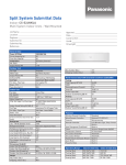
Order No: PAPAMY1204088CE Indoor Unit CS-E18NKUA CS-E24NKUA Outdoor Unit CU-E18NKUA CU-E24NKUA WARNING This service information is designed for experienced repair technicians only and is not designed for use by the general public. It does not contain warnings or cautions to advise non-technical individuals of potential dangers in attempting to service a product. Products powered by electricity should be serviced or repaired only by experienced professional technicians. Any attempt to service or repair the products dealt with in this service information by anyone else could result in serious injury or death. PRECAUTION OF LOW TEMPERATURE In order to avoid frostbite, be assured of no refrigerant leakage during the installation or repairing of refrigerant circuit. TABLE OF CONTENTS 1. Safety Precautions.............................................3 2. Specification .......................................................5 3. Features ..............................................................8 4. Location of Controls and Components ...........9 4.1 4.2 4.3 Indoor Unit....................................................9 Outdoor Unit .................................................9 Remote Control ............................................9 5. Dimensions .......................................................10 5.1 5.2 Indoor Unit..................................................10 Outdoor Unit ...............................................11 6. Refrigeration Cycle Diagram...........................12 7. Block Diagram ..................................................13 8. Wiring Connection Diagram............................14 8.1 8.2 Indoor Unit..................................................14 Outdoor Unit ...............................................15 9. Electronic Circuit Diagram ..............................16 9.1 9.2 Indoor Unit..................................................16 Outdoor Unit ...............................................17 10. Printed Circuit Board .......................................18 10.1 10.2 Indoor Unit..................................................18 Outdoor Unit ...............................................20 11. Installation Instruction.....................................22 11.1 11.2 11.3 11.4 Select the Best Location ............................22 Indoor/Outdoor Unit Installation Diagram...22 Indoor Unit..................................................23 Outdoor Unit ...............................................27 12. Operation Control.............................................30 12.1 Basic Function............................................30 © Panasonic Appliances Air-Conditioning (M) Sdn. Bhd. 2012. Unauthorized copying and distribution is a violation of law. 12.2 12.3 12.4 12.5 Indoor Fan Motor Operation .......................31 Outdoor Fan Motor Operation ....................32 Airflow Direction..........................................32 Quiet Operation (Cooling Mode/Cooling Area of Dry Mode)...............................................33 12.6 Quiet Operation (Heating) ..........................34 12.7 Powerful Mode Operation...........................34 12.8 Timer Control..............................................35 12.9 Auto Restart Control ...................................35 12.10 Indication Panel ..........................................35 13. Protection Control............................................36 13.1 13.2 Protection Control For All Operations.........36 Protection Control For Cooling & Soft Dry Operation....................................................37 14. Servicing Mode .................................................40 14.1 14.2 Auto Off/On Button .....................................40 Remote Control Button...............................41 15. Troubleshooting Guide....................................42 15.1 15.2 15.3 15.4 Refrigeration Cycle System........................42 Breakdown Self Diagnosis Function...........44 Error Code Table ........................................45 Self-diagnosis Method................................47 16. Disassembly and Assembly Instructions ......67 16.1 Indoor Electronic Controllers, Cross Flow Fan and Indoor Fan Motor Removal Procedures ..................................67 17. Technical Data ..................................................71 17.1 Operation Characteristics...........................71 18. Exploded View and Replacement Parts List .....................................................................79 18.1 18.2 Indoor Unit ..................................................79 Outdoor Unit ...............................................81 2 1. Safety Precautions Read the following “SAFETY PRECAUTIONS” carefully before perform any servicing. Electrical work must be installed or serviced by a licensed electrician. Be sure to use the correct rating of the power plug and main circuit for the model installed. The caution items stated here must be followed because these important contents are related to safety. The meaning of each indication used is as below. Incorrect installation or servicing due to ignoring of the instruction will cause harm or damage, and the seriousness is classified by the following indications. WARNING This indication shows the possibility of causing death or serious injury CAUTION This indication shows the possibility of causing injury or damage to properties. The items to be followed are classified by the symbols: This symbol denotes item that is PROHIBITED from doing. Carry out test run to confirm that no abnormality occurs after the servicing. Then, explain to user the operation, care and maintenance as stated in instructions. Please remind the customer to keep the operating instructions for future reference. WARNING 1. Do not modify the machine, part, material during repairing service. 2. If wiring unit is supplied as repairing part, do not repair or connect the wire even only partial wire break. Exchange the whole wiring unit. 3. Do not wrench the fasten terminal. Pull it out or insert it straightly. 4. Engage authorized dealer or specialist for installation and servicing. If installation of servicing done by the user is defective, it will cause water leakage, electrical shock or fire. 5. Install according to this installation instructions strictly. If installation is defective, it will cause water leakage, electric shock or fire. 6. Use the attached accessories parts and specified parts for installation and servicing. Otherwise, it will cause the set to fall, water leakage, fire or electrical shock. 7. Install at a strong and firm location which is able to withstand the set’s weight. If the strength is not enough or installation is not properly done, the set will drop and cause injury. 8. For electrical work, follow the local national wiring standard, regulation and the installation instruction. An independent circuit and single outlet must be used. If electrical circuit capacity is not enough or defect found in electrical work, it will cause electrical shock or fire. 9. This equipment is strongly recommended to be installed with Earth Leakage Circuit Breaker (ELCB) or Residual Current Device (RCD). Otherwise, it may cause electrical shock and fire in case equipment breakdown or insulation breakdown. 10. Do not use joint cable for indoor/outdoor connection cable. Use the specified indoor/outdoor connection cable, refer to installation instruction CONNECT THE CABLE TO THE INDOOR UNIT and connect tightly for indoor/outdoor connection. Clamp the cable so that no external force will be acted on the terminal. If connecting or fixing is not perfect, it will cause heat up or fire at the connection. 11. Wire routing must be properly arranged so that control board cover is fixed properly. If control board cover is not fixed perfectly, it will cause heat-up or fire at the connection point of terminal, fire or electrical shock. 12. When install or relocate air conditioner, do not let any substance other than the specified refrigerant, eg. air etc. mix into refrigeration cycle (piping). (Mixing of air etc. will cause abnormal high pressure in refrigeration cycle and result in explosion, injury etc.). 13. Do not install outdoor unit near handrail of veranda. When installing air-conditioner unit at veranda of high rise building, child may climb up to outdoor unit and cross over the handrail and causing accident. 14. This equipment must be properly earthed. Earth line must not be connected to gas pipe, water pipe, earth of lightning rod and telephone. Otherwise, it may cause electrical shock in case equipment breakdown or insulation breakdown. 15. Keep away from small children, the thin film may cling to nose and mouth and prevent breathing. 16. Do not use unspecified cord, modified cord, joint cord or extension cord for power supply cord. Do not share the single outlet with other electrical appliances. Poor contact, poor insulation or over current will cause electrical shock or fire. 17. Tighten the flare nut with torque wrench according to specified method. If the flare nut is over-tightened, after a long period, the flare may break and cause refrigerant gas leakage. 18. For R410A models, when connecting the piping, do not use any existing (R22) pipes and flares nuts. Using such same may cause abnormally high pressure in the refrigeration cycle (piping), and possibly result in explosion and injury. In case of using existing (R22) pipes during installation of R410A models, must carry out pump down properly to collect back the refrigerant and oil before installation new unit. Thickness of copper pipes used with R410A must be more than 1/64". Never use copper pipes thinner than 1/64". It is desirable that the amount of residual oil is less than 0.0006 oz/ft. 3 19. During installation, install the refrigerant piping properly before run the compressor. (Operation of compressor without fixing refrigeration piping and valves at opened condition will cause suck-in of air, abnormal high pressure in refrigeration cycle and result in explosion, injury etc.). 20. During pump down operation, stop the compressor before remove the refrigeration piping. (Removal of refrigeration piping while compressor is operating and valves are opened condition will cause suck-in of air, abnormal high pressure in refrigeration cycle and result in explosion, injury etc.). 21. After completion of installation or service, confirm there is no leakage of refrigerant gas. It may generate toxic gas when the refrigerant contacts with fire. 22. Ventilate if there is refrigerant gas leakage during operation. It may cause toxic gas when the refrigerant contacts with fire. 23. Do not insert your fingers or other objects into the unit, high speed rotating fan may cause injury. 24. Must not use other parts except original parts describe in catalog and manual. 25. Using of refrigerant other than the specified type may cause product damage, burst and injury etc. CAUTION 1. Do not install the unit at place where leakage of flammable gas may occur. In case gas leaks and accumulates at surrounding of the unit, it may cause fire. 2. Carry out drainage piping as mentioned in installation instructions. If drainage is not perfect, water may enter the room and damage the furniture. 3. Tighten the flare nut with torque wrench according to specified method. If the flare nut is over-tightened, after a long period, the flare may break and cause refrigerant gas leakage. 4. Do not touch outdoor unit air inlet and aluminium fin. It may cause injury. 5. Select an installation location which is easy for maintenance. 6. Pb free solder has a higher melting point than standard solder; typically the melting point is 50°F – 70°F (30°C – 40°C) higher. Please use a high temperature solder iron. In case of the soldering iron with temperature control, please set it to 700 ± 20°F (370 ± 10°C). Pb free solder will tend to splash when heated too high (about 1100°F / 600°C). 7. Power supply connection to the room air conditioner. Power supply cord shall be UL listed or CSA approved 3 conductor with minimum AWG12 wires. Power supply point should be in an easily accessible place for power disconnection in case of emergency. In some countries, permanent connection of this air conditioner to the power supply is prohibited. Fix power supply connection to a circuit breaker for the permanent connection. Use NRTL approved fuse or circuit breaker (rating refers to name plate) for the permanent connection. 8. Do not release refrigerant during piping work for installation, servicing, reinstallation and during repairing a refrigerant parts. Take care of the liquid refrigerant, it may cause frostbite. 9. Installation or servicing work: It may need two people to carry out the installation or servicing work. 10. Do not install this appliance in a laundry room or other location where water may drip from the ceiling, etc. 11. Do not sit or step on the unit, you may fall down accidentally. 12. Do not touch the sharp aluminium fins or edges of metal parts. If you are required to handle sharp parts during installation or servicing, please wear hand glove. Sharp parts may cause injury. 4 2. Specification Model Indoor CS-E18NKUA CS-E24NKUA Outdoor CU-E18NKUA CU-E24NKUA ARI ARI Performance Test Condition Phase, Hz Power Supply Cooling Capacity 230 208 230 Min. Mid. Max. Min. Mid. Max. Min. Mid. Max. Min. Mid. Max. kW 1.70 5.01 5.80 1.70 5.01 5.80 1.70 7.02 8.00 1.70 7.02 8.00 BTU/h 5800 17100 19800 5800 17100 19800 5800 24000 27200 5800 24000 27200 A - 7.20 - - 6.30 - - 11.90 - - 10.80 - Input Power W 430 1.30k 1.60k 430 1.30k 1.60k 430 2.35k 2.72k 430 2.35k 2.72k W/W 3.95 3.85 3.63 3.95 3.85 3.63 3.95 2.99 2.94 3.95 2.99 2.94 Btu/hW 13.45 13.15 12.35 13.45 13.15 12.35 13.45 10.20 10.00 13.45 10.20 10.00 % - 87 - - 90 - - 95 - - 95 - EER Power Factor Outdoor Noise (H / L / QLo) dB-A 47 / 39 / 36 47 / 39 / 36 48 / 40 / 37 48 / 40 / 37 Power Level dB 63 / - / - 63 / - / - 64 / - / - 64 / - / - dB-A 49 / - / - 49 / - / - 51 / - / - 51 / - / - Power Level dB 63 / - / - 63 / - / - 65 / - / - 65 / - / - Capacity Heating Single, 60 208 Running Current Indoor Noise (H / L / QLo) kW 1.70 6.00 BTU/h 5800 6.10 1.70 20400 20800 6.00 5800 6.10 20400 20800 1.70 8.46 5800 8.56 1.70 28800 29200 8.46 5800 8.56 28800 29200 Running Current A - 8.60 - - 7.50 - - 12.60 - - 11.40 - Input Power W 380 1.60k 1.65k 380 1.60k 1.65k 380 2.50k 2.66k 380 2.50k 2.66k W/W 4.47 3.74 3.70 4.47 3.75 3.70 4.47 3.38 3.22 4.47 3.38 3.22 Btu/hW 15.25 12.75 12.60 15.25 12.75 12.60 15.25 11.50 10.95 15.25 11.50 10.95 % - 89 - - 93 - - 95 - - 95 - COP Power Factor Indoor Noise (H / L / QLo) Outdoor Noise (H / L / QLo) dB-A 46 / 39 / 36 46 / 39 / 36 48 / 40 / 37 48 / 40 / 37 Power Level dB 62 / - / - 62 / - / - 64 / - / - 64 / - / - dB-A 51 / - / - 51 / - / - 53 / - / - 53 / - / - Power Level dB 65 / - / - 65 / - / - 67 / - / - 67 / - / - Max Current (A) / Max Input Power (W) 11.6 / 2.49k 13.7 / 3.06k Starting Current (A) 8.6 12.6 Min Circuit Ampacity 15.0 20.0 Max. Overcurrent Protection 20.0 25.0 SEER / HSPF 18.00 / 8.50 17.50 / 8.50 Type Hermetic Motor / Rotary Hermetic Motor / Rotary Motor Type Brushless (4 poles) Brushless (4 poles) 1.7k 1.7k Cross-flow fan Cross-flow fan Compressor Output Power W Type Indoor Fan Single, 60 V Material ASG30K1 ASG30K1 Motor Type Transistor (8 poles) Transistor (8 poles) 94.8 - 94.8 94.8 - 94.8 Input Power W Output Power W Speed QLo rpm Lo rpm Me rpm Hi rpm SHi rpm 40 40 Cooling : 990 Heating : 1060 Cooling : 1090 Heating : 1160 Cooling : 1270 Heating : 1330 Cooling : 1460 Heating : 1500 Cooling : 1500 Heating : 1600 Cooling : 1020 Heating : 1150 Cooling : 1120 Heating : 1270 Cooling : 1300 Heating : 1430 Cooling : 1480 Heating : 1600 Cooling : 1600 Heating : 1600 5 Outdoor Fan Type Propeller Propeller Material PP PP Motor Type DC Motor (8 poles) DC Motor (8 poles) - - Input Power W Output Power W 60 60 rpm Cooling: 700 Heating: 700 Cooling: 700 Heating: 750 Speed Hi Moisture Removal L/h (Pt/h) 3 3 3 3 3 3 3 3 3 3 3 3 QLo m /min (ft /min) Lo m /min (ft /min) Me m /min (ft /min) Hi m /min (ft /min) SHi m /min (ft /min) Hi m /min (ft /min) Indoor Airflow Outdoor Airflow 1.4 (3.0) 3.6 (7.6) Cooling : 11.74 (410) Heating : 12.88 (450) Cooling : 13.15 (460) Heating : 14.32 (500) Cooling : 15.71 (550) Heating : 16.76 (590) Cooling : 18.40 (650) Heating : 19.20 (680) Cooling : 18.97 (670) Heating : 20.64 (730) Cooling : 54.5 (1925) Cooling : 54.5 (1925) Heating : 54.5 (1925) Heating : 54.5 (1925) Cooling : 11.97 (420) Heating : 13.60 (480) Cooling : 13.37 (470) Heating : 15.25 (540) Cooling : 15.88 (560) Heating : 17.45 (620) Cooling : 18.40 (650) Heating : 19.80 (700) Cooling : 20.07 (710) Heating : 19.80 (700) Cooling : 54.5 (1925) Cooling : 54.5 (1925) Heating : 56.5 (1995) Heating : 56.5 (1995) Control Device Refrigeration Cycle Dimension Weight Expansion Valve Expansion Valve Refrigerant Oil cm FV50S (800) FV50S (800) Refrigerant Type g (oz) R410A, 1.60k (56.5) R410A, 1.85k (65.3) Height(I/D / O/D) mm (inch) 290 (11-7/16) / 795 (31-5/16) 290 (11-7/16) / 795 (31-5/16) Width (I/D / O/D) mm (inch) 1070 (42-5/32) / 875 (34-15/32) 1070 (42-5/32) / 875 (34-15/32) Depth (I/D / O/D) mm (inch) 235 (9-9/32) / 320 (12-5/8) 235 (9-9/32) / 320 (12-5/8) Net (I/D / O/D) kg (lb) Pipe Diameter (Liquid / Gas) Piping 3 mm (inch) 12 (26) 60 (132) 6.35 (1/4) / 12.70 (1/2) 12 (26) 60 (132) 6.35 (1/4) / 15.88 (5/8) Standard length m (ft) 7.5 (24.6) 7.5 (24.6) Length range (min – max) m (ft) 3 (9.8) ~ 30.5 (100.0) 3 (9.8) ~ 30.5 (100.0) I/D & O/D Height different m (ft) 15 (49.2) 15 (49.2) Additional Gas Amount g/m (oz/ft) 25 (0.3) 25 (0.3) Length for Additional Gas m (ft) 10 (32.8) 10 (32.8) Inner Diameter mm 16.7 16.7 Length mm 650 650 Aluminium (Pre Coat) Aluminium (Pre Coat) Drain Hose Fin Material Fin Type Indoor Heat Exchanger Row x Stage x FPI Size (W x H x L) mm Fin Material Outdoor Fin Type Heat Row x Stage x FPI Exchanger Slit Fin Slit Fin 2 x 15 x 21 2 x 15 x 21 25.4 x 315 x 810 25.4 x 315 x 810 Aluminium (Blue coated) Aluminium (Blue coated) Corrugate Fin Corrugate Fin 2 x 36 x 19 2 x 36 x 19 36.4 x 756 x 869 897 36.4 x 756 x 869 897 Material Polypropelene Polypropelene Type One-touch One-touch Outdoor Outdoor - - Thermostat - - Protection Device - - Size (W x H x L) Air Filter mm Power Supply Power Supply Cord A 6 1. 2. 3. DRY BULB WET BULB DRY BULB WET BULB Indoor Operation Range (Cooling) Maximum 89.6 73.4 89.6 73.4 Minimum 60.8 51.8 60.8 51.8 Outdoor Operation Range (Cooling) Maximum 109.4 78.8 109.4 78.8 Minimum 0.0 - 0.0 - Indoor Operation Range (Heating) Maximum 86.0 - 86.0 - Minimum 60.8 - 60.8 - Outdoor Operation Range (Heating) Maximum 75.2 64.4 75.2 64.4 Minimum 5.0 3.2 5.0 3.2 Cooling capacities are based on indoor temperature of 80°F DRY BULB, 67°F WET BULB and outdoor air temperature of 95°F DRY BULB, 75°F WET BULB. Heating capacities are based on indoor temperature of 70°F DRY BULB, 60°F WET BULB and outdoor air temperature of 47°F DRY BULB, 43°F WET BULB. Specifications are subjected to change without prior notice for further improvement. 7 3. Features Inverter Technology o Wider output power range o Energy saving o Quick Cooling o More precise temperature control Environment Protection o Non-ozone depletion substances refrigerant (R410A) Long Installation Piping o Long piping up to 100 foot Easy to use remote control Quality Improvement o Random auto restart after power failure for safety restart operation o Gas leakage protection o Prevent compressor reverse cycle o Inner protector to protect Compressor o Noise prevention during soft dry operation Operation Improvement o Quiet mode to reduce the indoor unit operating sound o Powerful mode to reach the desired room temperature quickly Serviceability Improvement o Breakdown Self Diagnosis function 8 4. Location of Controls and Components 4.1 Indoor Unit 4.2 Outdoor Unit 4.3 Remote Control 9 5. Dimensions 5.1 Indoor Unit 10 5.2 Outdoor Unit 11 6. Refrigeration Cycle Diagram 12 7. Block Diagram 13 8. Wiring Connection Diagram 8.1 Indoor Unit 14 8.2 Outdoor Unit 15 9. Electronic Circuit Diagram 9.1 Indoor Unit 16 9.2 Outdoor Unit 17 10. Printed Circuit Board 10.1 10.1.1 Indoor Unit Main Printed Circuit Board 18 10.1.2 Power Printed Circuit Board 10.1.3 Indicator and Receiver Printed Circuit Board 19 10.2 10.2.1 Outdoor Unit Main Printed Circuit Board 20 10.2.2 Noise Filter Printed Circuit Board 21 11. Installation Instruction 11.1 11.1.1 11.2 Indoor Unit Do not install the unit in excessive oil fume area such as kitchens, workshops and etc. There should not be any heat source or steam near the unit. There should not be any obstacles blocking the air circulation. A place where air circulation in the room is good. A place where drainage can be easily done. A place where noise prevention is taken into consideration. Do not install the unit near the door way. Ensure the spaces indicated by arrows from the wall, ceiling, fence or other obstacles. Recommended installation height for indoor unit shall be at least 8.2 ft. 11.1.2 Select the Best Location Outdoor Unit If an awning is built over the unit to prevent direct sunlight or rain, be careful that heat radiation from the condenser is not obstructed. There should not be any animal or plant which could be affected by hot air discharged. Keep the spaces indicated by arrows from wall, ceiling, fence or other obstacles. Do not place any obstacles which may cause a short circuit of the discharged air. If piping length is over the [piping length for additional gas], additional refrigerant should be added as shown in the table. Recommended installation height for outdoor unit should be above the seasonal snow level. Example: For E18NKUA If the unit is installed at 41 ft distance, the quantity of additional refrigerant should be 2.46 oz .... (41 - 32.8) ft x 0.3 oz/ft = 2.46 oz. 22 Indoor/Outdoor Unit Installation Diagram 11.3 11.3.1 Indoor Unit How to Fix Installation Plate The mounting wall must be strong and solid enough to prevent it from the vibration. The center of installation plate should be at more than c at right and left of the wall. The distance from installation plate edge to ceiling should more than d. From installation plate left edge to unit’s left side is e. From installation plate right edge to unit’s right side is f. B ○ : For left side piping, piping connection for liquid should be about g from this line. : For left side piping, piping connection for gas should be about h from this line. 1 2 11.3.2 Mount the installation plate on the wall with 5 screws or more (at least 5 screws). (If mounting the unit on the concrete wall, consider using anchor bolts.) o Always mount the installation plate horizontally by aligning the marking-off line with the thread and using a level gauge. Drill the piping plate hole with ø2-3/4" hole-core drill. o Line according to the left and right side of the installation plate. The meeting point of the extended line is the center of the hole. Another method is by putting measuring tape at position as shown in the diagram above. The hole center is obtained by measuring the distance namely 5-1/16" for left and right hole respectively. o Drill the piping hole at either the right or the left and the hole should be slightly slanting to the outdoor side. To Drill a Hole in the Wall and Install a Sleeve of Piping 1 2 3 Insert the piping sleeve to the hole. Fix the bushing to the sleeve. Cut the sleeve until it extrudes about 19/32" from the wall. 4 Finish by sealing the sleeve with putty or caulking compound at the final stage. 23 11.3.3 Indoor Unit Installation 11.3.4 For the right rear piping 11.3.5 For the right bottom piping 11.3.6 For the embedded piping (This can be used for left rear piping and bottom piping also.) 24 11.3.7 Connect the Cable to the Indoor Unit 1. The inside and outside connecting cable can be connected without removing the front grille. 2. Unscrew the conduit cover and fix the conduit connector to conduit cover with lock nut, then secure it against chassis. 3. Connecting wire between indoor unit and outdoor unit should be UL listed or CSA approved 4 conductor wires minimum AWG16 in accordance with local electric codes. o Ensure the colour of wires of outdoor unit and terminal number are the same as the indoor's repectively. o This equipment must be properly earthed. Earth lead wire shall be Yellow/Green (Y/G) in colour and shall be longer than other lead wires as shown in the figure for electrical safety in case of the slipping. 25 11.3.8 11.3.9 1 2 3 Wiring Stripping and connecting requirement Cutting and flaring the piping Please cut using pipe cutter and then remove the burrs. Remove the burrs by using reamer. If burrs are not removed, gas leakage may be caused. Turn the piping end down to avoid the metal powder entering the pipe. Please make flare after inserting the flare nut onto the copper pipes. 26 11.4 Outdoor Unit 11.4.1 Install the Outdoor Unit After selecting the best location, start installation according to indoor/outdoor unit installation diagram. 1 Fix the unit on concrete or rigid frame firmly and horizontally by bolt nut (ø13/32"). 2 When installing at roof, please consider strong wind and earthquake. Please fasten the installation stand firmly with bolt or nails. Model E18NKUA, E24NKUA 11.4.2 11.4.2.1 Connecting the piping to indoor C 5/8" D 14-3/16" Do not over tighten, over tightening may cause gas leakage. Piping size 1/4" 3/8" 1/2" 5/8" 3/4" Connect the piping Align the center of piping and sufficiently tighten the flare nut with fingers. Further tighten the flare nut with torque wrench in specified torque as stated in the table. Connecting the piping to outdoor Decide piping length and then cut by using pipe cutter. Remove burrs from cut edge. Make flare after inserting the flare nut (locate at valve) onto the copper pipe. Align center of piping to valves and then tighten with torque wrench to the specified torque as stated in the table. 11.4.2.3 B 5-5/32" Connect the Piping Please make flare after inserting flare nut (locate at joint portion of tube assembly) onto the copper pipe. (In case of using long piping) 11.4.2.2 A 24-1/8" Gas Leak Checking Pressure test to system to 400 PSIG with dry nitrogen, in stages. Thoroughly leak check the system. If the pressure holds, release the nitrogen and proceed to section 4. 27 Torque 13.3 Ibf.ft 31.0 Ibf.ft 40.6 Ibf.ft 47.9 Ibf.ft 73.8 Ibf.ft 11.4.3 Evacuation of the equipment WHEN INSTALLING AN AIR CONDITIONER, BE SURE TO EVACUATE THE AIR INSIDE THE INDOOR UNIT AND PIPES in the following procedures. 1. Connect a charging hose with a push pin to the Low side of a charging set and the service port of the 3-way valve. 2. Connect the micron gauge between vacuum pump and service port of outdoor units. 3. Turn on the power switch of the vacuum pump and make sure that connect digital micron gauge and to pull down to a value of 500 microns. 4. To make sure micron gauge a value 500 microns and close the low side valve of the charging set and turn off the vacuum pump. 5. Disconnect the vacuum pump house from the service port of the 3-way valve. 6. Tighten the service port caps of the 3-way valve at a torque of 13.3 Ibf.ft with a torque wrench. 7. Remove the valve caps of both of the 2-way valve and 3-way valve. Position both of the valves to “Open” using a hexagonal wrench (5/32"). 8. Mount valve caps onto the 2-way valve and the 3-way valve. o Be sure to check for gas leakage. 11.4.4 Connect the Cable to the Outdoor Unit 1. 2. 3. 4. 5. 6. Remove control board cover (Resin and Metal). Remove particular plate. Remove plugs. Fix the conduit connectors to the knockout holes with lock-nuts, then secure them against the side panel. All wires pass through conduits & particular plate’s opening hole. Connecting wire between indoor unit and outdoor unit should be UL listed or CSA approved 4 conductor wires minimum AWG16 in accordance with local electric codes. 7. Wire connection to the power supply (208/230V 60Hz) through circuit breaker. o Connect the UL listed or CSA approved wires minimum AWG12 to the terminal board, and connect the other end of the wires to ELCB / GFCI. 8. Connect the power supply cord and connecting wire between indoor unit and outdoor unit according to the diagram below. 28 9. Secure the wire onto the control board with the holder (clamper). 10. After completing wiring connections, reattach the particular plate control board cover (metal and resin) and the original position with the screws. 11. For wire stripping and connection requirement, refer to instruction 11.3.7 of indoor unit. This equipment must be properly earthed. Earth lead wire shall be Yellow/Green (Y/G) in colour and longer than other lead wires as shown in the figure for electrical safety in case of the slipping. 11.4.5 Piping Insulation 1. Please carry out insulation at pipe connection portion as mentioned in Indoor/Outdoor Unit Installation Diagram. Please wrap the insulated piping end to prevent water from going inside the piping. 2. If drain hose or connecting piping is in the room (where dew may form), please increase the insulation by using POLY-E-FOAM with thickness 1/4" or above. 29 12. Operation Control 12.1 Basic Function Inverter control, which equipped with a microcomputer in determining the most suitable operation mode as time passes, automatically adjusts output power for maximum comfort always. In order to achieve the suitable operation mode, the microcomputer maintains the set temperature by measuring the temperature of the environment and performing temperature shifting. The compressor at outdoor unit is operating following the frequency instructed by the microcomputer at indoor unit that judging the condition according to internal setting temperature and intake air temperature. 12.1.1 Internal Setting Temperature Once the operation starts, remote control setting temperature will be taken as base value for temperature shifting processes. These shifting processes are depending on the air conditioner settings and the operation environment. The final shifted value will be used as internal setting temperature and it is updated continuously whenever the electrical power is supplied to the unit. 12.1.2 12.1.2.1 12.1.3.1 Soft Dry Operation Thermostat control Compressor is OFF when Intake Temperature - Internal Setting Temperature < -3.6°F. Compressor is ON after waiting for 3 minutes, if the Intake Air Temperature - Internal Setting Temperature > Compressor OFF point. 12.1.4 12.1.4.1 Thermostat control Compressor is OFF when intake Air Temperature - Internal Setting Temperature < -2.7F. Compressor is ON after waiting for 3 minutes, if the Intake Temperature - Internal Setting Temperature > Compressor OFF point. 12.1.3 Cooling Operation Heating Operation Thermostat control Compressor is OFF when Intake Temperature - Internal Setting Temperature > +3.6°F. Compressor is ON after waiting for 3 minutes, if the Intake Air Temperature - Internal Setting Temperature < Compressor OFF point 30 12.1.5 This mode can be set using remote control and the operation is decided by remote control setting temperature, remote control operation mode and indoor intake air temperature. During operation mode judgment, indoor fan motor (with speed of Lo-) is running for 30 seconds to detect the indoor intake air temperature. Every 10 minutes, the indoor temperature is judged. For the 1st judgment o If indoor intake temperature - remote control setting temperature ≥ 3.6°F, COOL mode is decided. o If -3.6°F ≤ indoor intake temperature - remote control setting temperature < 3.6°F, DRY mode is decided. o If indoor intake temperature - remote control setting temperature < -3.6°F, HEAT mode is decided. For the 2nd judgment onwards o If indoor intake temperature - remote control setting temperature ≥ 5.4°F, if previous operate in DRY mode, then continue in DRY mode. Otherwise COOL mode is decided. o If -3.6°F ≤ indoor intake temperature - remote control setting temperature < 5.4°F, maintain with previous mode. o If indoor intake temperature - remote control setting temperature < -3.6°F, HEAT mode is decided. 12.2 12.2.1 Automatic Operation Indoor Fan Motor Operation Basic Rotation Speed (rpm) Manual Fan Speed [Cooling, Dry] o Fan motor’s number of rotation is determined according to remote control setting. Remote control ○ ○ ○ ○ ○ Tab Hi Me+ Me Me- Lo [Heating] o Fan motor’s number of rotation is determined according to remote control setting. Remote control ○ ○ ○ ○ ○ Tab Shi Me+ Me Me- Lo Auto Fan Speed [Cooling, Dry] o According to room temperature and setting temperature, indoor fan speed is determined automatically. o The indoor fan will operate according to pattern below. o During operation, indoor fan motor may stop due to odor prevention. 31 [Heating] o According to indoor pipe temperature, automatic heating fan speed is determined as follows. Feedback control o Immediately after the fan motor started, feedback control is performed once every second. o During fan motor on, if fan motor feedback ≥ 2550 rpm or < 50 rpm continue for 10 seconds, then fan motor error counter increase, fan motor is then stop and restart. If the fan motor counter becomes 7 times, then H19 - fan motor error is detected. Operation stops and cannot on back. 12.3 Outdoor Fan Motor Operation Outdoor fan motor is operated with one fan speed only. It starts when compressor starts operation and it stops 30 seconds after compressor stops operation. ON ON Compressor OFF ON Outdoor Fan 12.4 ON OFF Airflow Direction There are two types of airflow, vertical airflow (directed by horizontal vane) and horizontal airflow (directed by vertical vanes). Control of airflow direction can be automatic (angles of direction is determined by operation mode, heat exchanger temperature and intake air temperature) and manual (angles of direction can be adjusted using remote control). 12.4.1 Fan Speed 30 sec Vertical Airflow Automatic vertical airflow direction can be set using remote control; the vane swings up and down within the angles as stated above. For heating mode operation, the angle of the vane depands on the indoor heat exchanger temperature as Figure 1 below. When the air conditioner is stopped using remote control, the vane will shift to close position. 32 Manual vertical airflow direction can be set using remote control; the angles of the vane are as stated above and the positions of the vane are as Figure 2 below. When the air conditioner is stopped using remote control, the vane will shift to close position. 12.4.2 Horizontal Airflow Automatic horizontal airflow direction can be set using remote control; the vane swings left and right within the angles as stated below. For heating mode operation, the angle of the vane depends on the indoor heat exchanger temperature as Figure 1 below. Manual vertical airflow direction can be set using remote control; the angles of the vane are as stated below and the positions of the vane are as figure below: 12.5 Quiet Operation (Cooling Mode/Cooling Area of Dry Mode) Purpose o To provide quiet cooling operation compare to normal operation. Control condition o Quiet operation start condition When “Quiet” button at remote control is pressed. Quiet LED illuminates. o Quiet operation stop condition When one of the following conditions is satisfied, quiet operation stops: Powerful button is pressed. Stop by OFF/ON button. OFF Timer activates. Quiet button is pressed again. When quiet operation is stopped, operation is shifted to normal operation with previous setting. When fan speed is changed, quiet operation is shifted to quiet operation of the new fan speed. When operation mode is changed, quiet operation is shifted to quiet operation of the new mode. 33 During quiet operation, if ON timer activates, quiet operation maintains. After off, when on back, quiet operation is not memorised. Control contents o Auto fan speed is change from normal setting to quiet setting of respective fan speed. This is to reduce sound of Hi, Me, Lo for 3dB. o Manual fan speed for quiet operation is -1 step from setting fan speed. 12.6 Quiet Operation (Heating) Purpose o To provide quiet heating operation compare to normal operation. Control condition o Quiet operation start condition When “Quiet” button at remote control is pressed. Quiet LED illuminates. o Quiet operation stop condition When one of the following conditions is satisfied, quiet operation stops: Powerful button is pressed. Stop by OFF/ON button. Timer “off” activates. Quiet button is pressed again. When quiet operation is stopped, operation is shifted to normal operation with previous setting. When fan speed is changed, quiet operation is shifted to quiet operation of the new fan speed. When operation mode is changed, quiet operation is shifted to quiet operation of the new mode. During quiet operation, if timer “on” activates, quiet operation maintains. After off, when on back, quiet operation is not memorised. Control contents o Fan speed auto Indoor FM RPM depends on pipe temperature sensor of indoor heat exchanger. Auto fan speed is changed from normal setting to quiet setting of respective fan speed. This is to reduce sound of Hi, Me, Lo for 3dB. o Fan speed manual Manual fan speed for quiet operation is -1 step from setting fan speed. 12.7 Powerful Mode Operation When the powerful mode is selected, the internal setting temperature will shift lower up to 3.6°F (for Cooling/Soft Dry) or higher up to 6.3°F (for Heating) than remote control setting temperature for 20 minutes to achieve the setting temperature quickly. 34 12.8 12.8.1 OFF Timer Control OFF Timer can be set using remote control, the unit with timer set will stop at set time. 12.9 ON Timer Control ON Timer can be set using remote control, where the unit with timer set will start operation earlier than the setting time. This is to provide a comfortable environment when reaching the set ON time. 60 minutes before the set ON time, indoor (at fan speed of Lo-) and outdoor fan motor start operation for 30 seconds to determine the indoor intake air temperature and outdoor air temperature in order to judge the operation starting time. From the above judgment, the decided operation will start operation earlier than the set time as shown below. 12.8.2 Timer Control Auto Restart Control When the power supply is cut off during the operation of air conditioner, the compressor will re-operate within three to four minutes (there are 10 patterns between 2 minutes 58 seconds and 3 minutes 52 seconds to be selected randomly) after power supply resumes. This type of control is not applicable during ON/OFF Timer setting. 12.10 Indication Panel Note: If POWER LED is blinking, the possible operation of the unit are Hot Start, during Deice operation, operation mode judgment, or ON timer sampling. If Timer LED is blinking, there is an abnormality operation occurs. 35 13. Protection Control 13.1 13.1.1 30 Seconds Forced Operation Once the air conditioner is turned on, the compressor will not stop within 30 seconds in a normal operation although the intake air temperature has reached the thermo-off temperature. However, force stop by pressing the OFF/ON button at the remote control is permitted or the Auto OFF/ON button at indoor unit. The reason for the compressor to force operation for minimum 30 seconds is to allow the refrigerant oil run in a full cycle and return back to the outdoor unit. 13.1.3 Restart Control (Time Delay Safety Control) The compressor will not turn on within 3 minutes from the moment operation stops, although the unit is turned on again by pressing OFF/ON button at remote control within this period. This control is not applicable if the power supply is cut off and on again. This phenomenon is to balance the pressure inside the refrigerant cycle. 13.1.2 Protection Control For All Operations Total Running Current Control When the outdoor unit total running current (AC) exceeds X value, the frequency instructed for compressor operation will be decreased. If the running current does not exceed X value for 5 seconds, the frequency instructed will be increased. However, if total outdoor unit running current exceeds Y value, compressor will be stopped immediately for 3 minutes. Model Operation Mode Cooling / Soft Dry (A) Cooling / Soft Dry (B) Heating E18NKUA X (A) Y (A) 10.85 19.30 9.84 19.30 11.29 19.30 E24NKUA X (A) Y (A) 12.47 19.30 11.46 19.30 13.63 19.30 1. The first 30 minutes of cooling operation, (A) will be applied. 13.1.4 IPM (Power Transistor) Prevention Control Overheating Prevention Control o When the IPM temperature rises to 212°F, compressor operation will stop immediately. o Compressor operation restarts after 3 minutes the temperature decreases to 203°F. DC Peak Current Control o When electric current to IPM exceeds set value of 29.9A, the compressor will stop operate. Then, operation will restart after 3 minutes. o If the set value is exceeded again more than 30 seconds after the compressor starts, the operation will restart after 2 minute. o If the set value is exceeded again within 30 seconds after the compressor starts, the operation will restart after 1 minute. If this condition repeats continuously for 7 times, all indoor and outdoor relays will be cut off. Timer LED will be blinking (F99 is indicated). 36 13.1.5 Instructed frequency for compressor operation will be regulated by compressor discharge temperature. The changes of frequency are as below. If compressor discharge temperature exceeds 233.6°F, compressor will be stopped, occurs 4 times per 20 minutes, timer LED will be blinking. “F97” is indicated. 13.1.6 Low Frequency Protection Control 1 When the compressor operates at frequency lower than 25Hz continued for 240 minutes, the operation frequency will be changed to 24Hz for 2 minutes. 13.1.8 Low Pressure Protection Control (Gas Leakage Detection) For 5 minutes, the compressor continuously operates and outdoor total current is between 0.78A and 1.16A. During Cooling and Soft Dry operation: Indoor suction temperature – indoor piping temperature is below 39.2°F. During Heating operations : Indoor piping temperature - indoor suction is under 41.0°F. 13.1.7 Compressor Overheating Prevention Control Low Frequency Protection Control 2 When all below conditions comply, minimum limit of compressor will be set. E18NKUA, E24NKUA 13.2 13.2.1 Temperature, T, for: Cooling / Soft Dry Heating Indoor intake air (°F) T < 57.2 or T ≥ 86.0 T < 57.2 or T ≥ 82.4 Outdoor air (°F) T < 55.4 or T ≥ 100.4 T < 39.2 or T ≥ 75.2 Indoor heat exchanger (°F) T < 86.0 T ≥ 32.0 Protection Control For Cooling & Soft Dry Operation Outdoor Air Temperature Control The compressor operating frequency is regulated in accordance to the outdoor air temperature as shown in the diagram below. This control will begin 1 minute after the compressor starts. Compressor frequency will adjust based on outdoor air temperature. 37 13.2.2 Pipe temperature limitation / restriction. o Detects the outdoor pipe temperature and carry out restriction / limitation below (Limit the compressor operation frequency) o The compressor stops if outdoor pipe temperature exceeds 145.4°F. o If the compressor stops 4 times in 20 minutes, Timer LED blinks (“F95” indicated: Outdoor high pressure rise protection) 13.2.3 Freeze Prevention Control 2 Control start conditions o During Cooling operation and soft dry operation During thermo OFF condition, indoor intake temperature is less than 50.0°F or Compressor stops for freeze prevention control o Either one of the conditions above occurs 5 times in 60 minutes. Control contents o Operation stops o Timer LED blinks and “H99” indicated 13.2.5 Freeze Prevention Control 1 When indoor heat exchanger temperature is lower than 32°F continuously for 6 minutes, compressor will stops operation. Compressor will resume its operation 3 minutes after the indoor heat exchanger is higher than 41.0°F. At the same time, indoor fan speed will be higher than during its normal operation. If the indoor heat exchanger temperature is higher than 55.4°F for 5 minutes, the fan speed will return to its normal operation. 13.2.4 Cooling Overload Control Dew Prevention Control 1 To prevent dew formation at indoor unit discharge area. This control will be activated if: o Outdoor air temperature and Indoor pipe temperature judgment by microcontroller is fulfilled. o When Cooling or Dry mode is operated more than 20 minutes or more. This control stopped if: o Compressor stopped. o Remote control setting changed (fan speed / temperature). o Outdoor air temperature and indoor intake temperature changed. Fan speed, angle of louver (vertical airflow angle) will be adjusted accordingly in this control. 1. Fan speed will be increased slowly when control is activated until predetermine value. Compressor frequency will be regulated accordingly. 13.2.6 13.2.6.1 Protection Control For Heating Operation Intake Air Temperature Control Compressor will operate at limited freq., if indoor intake air temperature is 86.0°F or above. 13.2.6.2 Outdoor Air Temperature Control The Max current value is regulated when the outdoor air temperature rise above 57.2°F in order to avoid compressor overloading. 38 13.2.6.3 The compressor operating frequency is regulated in accordance to indoor heat exchanger temperature as shown below. If the heat exchanger temperature exceeds 140.0°F, compressor will stop. 13.2.6.4 Cold Draught Prevention Control When indoor pipe temperature is low, cold draught operation starts where indoor fan speed will be reduced or stop. Horizontal vane angle may be adjusted in Auto vane setting. 13.2.6.6 Low Temperature Compressor Oil Return Control In heating operation, if the indoor temperature falls below 17.6°F when compressor starts, the compressor frequency will be regulated up to 600 seconds. 13.2.6.5 Overload Protection Control Deice Operation When outdoor pipe temperature and outdoor air temperature is low, deice operation start where indoor fan motor and outdoor fan motor stop and operation LED blinks. Horizontal vane is closed during auto vane setting. 39 14. Servicing Mode 14.1 Auto Off/On Button 1 AUTO OPERATION MODE The Auto operation will be activated immediately once the Auto OFF/ON button is pressed. This operation can be used to operate air conditioner with limited function if remote control is misplaced or malfunction. 2 TEST RUN OPERATION (FOR PUMP DOWN/SERVICING PURPOSE) The Test Run operation will be activated if the Auto OFF/ON button is pressed continuously for more than 5 seconds. A “beep” sound will heard at the fifth seconds, in order to identify the starting of Test Run operation (Forced cooling operation). Within 5 minutes after Forced cooling operation start, the Auto OFF/ON button is pressed for more than 5 seconds. A 2 “beep” sounds will heard at the fifth seconds, in order to identify the starting of Forced heating operation. The Auto OFF/ON button may be used together with remote control to set / change the advance setting of air conditioner operation. 3 REMOTE CONTROL NUMBER SWITCH MODE The Remote Control Number Switch Mode will be activated if the Auto OFF/ON button is pressed continuously for more than 11 seconds (3 “beep” sounds will occur at 11th seconds to identify the Remote Control Number Switch Mode is in standby condition) and press “AC RESET” button and then press any button at remote control to transmit and store the desired transmission code to the EEPROM. There are 4 types of remote control transmission code could be selected and stored in EEPROM of indoor unit. The indoor unit will only operate when received signal with same transmission code from remote control. This could prevent signal interference when there are 2 or more indoor units installed nearby together. To change remote control transmission code, short or open jumpers at the remote control printed circuit board. Remote Control Printed Circuit Board Jumper A (J1) Jumper B (D2) Remote Control No. Short Open A (Default) Open Open B Short Short C Open Short D 4 During Remote Control Number Switch Mode, press any button at remote control to transmit and store the transmission code to the EEPROM. REMOTE CONTROL RECEIVING SOUND OFF/ON MODE The Remote Control Receiving Sound OFF/ON Mode will be activated if the Auto OFF/ON button is pressed continuously for more than 16 seconds (4 “beep” sounds will occur at 16th seconds to identify the Remote Control Receiving Sound OFF/ON Mode is in standby condition) and press “AC Reset” button at remote control. 40 Press Auto OFF/ON button to toggle remote control receiving sound. - Short “beep”: Turn OFF remote control receiving sound. - Long “beep”: Turn ON remote control receiving sound. After Auto OFF/ON button is pressed, the 20 seconds counter for Remote Control Receiving Sound OFF/ON Mode is restarted. 14.2 14.2.1 TIMER ▼ To change remote control display from Degree Celsius (°C) to Degree Fahrenheit (°F) o Press continuously for 10 seconds. 14.2.6 TIMER ▲ To change indoor unit indicator’s LED intensity: o Press continuously for 5 seconds. 14.2.5 RESET (AC) To restore the unit’s setting to factory default. o Press once to restore the unit’s setting 14.2.4 RESET (RC) To clear and restore the remote control setting to factory default. o Press once to clear the memory 14.2.3 SET Button To check remote control transmission code and store the transmission code to EEPROM o Press “Set” button continuously for 10 seconds by using pointer o Press “Timer Set” button unit a “beep” sound is heard as confirmation of transmission code change. 14.2.2 Remote Control Button CLOCK Button To change the remote control time format: o Press for more than 5 seconds 41 15. Troubleshooting Guide 15.1 Refrigeration Cycle System In order to diagnose malfunctions, make sure that there are no electrical problems before inspecting the refrigeration cycle. Such problems include insufficient insulation, problem with the power source, malfunction of a compressor and a fan. The normal outlet air temperature and pressure of the refrigeration cycle depends on various conditions, the standard values for them are shown in the table on the right. Normal Pressure and Outlet Air Temperature (Standard) Outlet air Gas Pressure Temperature PSI 2 (°F) (kg/cm G) Cooling Mode 130.53 ~ 174.04 (9 ~ 12) 53.6 ~ 60.8 Heating Mode 333.58 ~ 420.60 (23 ~ 29) 96.8 ~ 113.0 Condition: Indoor fan speed = High Outdoor temperature 95°F at cooling mode and 44.6°F at heating mode. Compressor operate at rated frequency 42 15.1.1 Relationship between the condition of the air conditioner and pressure and electric current Carry out the measurements of pressure, electric current, and temperature fifteen minutes after an operation is started. 43 15.2 15.2.1 Breakdown Self Diagnosis Function Self Diagnosis Function (Three Digits Alphanumeric Code) Once error occurred during operation, the unit will stop its operation, and Timer LED blinks. Although Timer LED goes off when power supply is turned off, if the unit is operated under a breakdown condition, the LED will ON again. In operation after breakdown repair, the Timer LED will not blink. The last error code (abnormality) will be stored in IC memory. 15.2.2 1 2 3 4 5 6 7 8 15.2.3 1 2 3 4 5 6 7 8 15.2.4 1 2 3 15.2.5 1 2 To Make a Diagnosis Timer LED starts to blink and the unit automatically stops the operation. Press the CHECK button on the remote control continuously for 5 seconds. “- -“ will be displayed on the remote control display. Note: Display only for “- -“ (No signal transmission, no receiving sound and no Power LED blinking) Press the TIMER ▲ or ▼ button on the remote control. The code “H00” (no abnormality) will be displayed and signal will be transmit to the main unit. Each press of the button (▲ or ▼) will increase error code number and transmit error code signal to the main unit. When the latest abnormality code on the main unit and code transmitted from the remote control are matched, Power LED will light up for 30 seconds and a “beep” sound (continuously for 4 seconds) will be heard. If no codes are matched, Power LED will light up for 0.5 seconds and no sound will be heard. The breakdown diagnosis mode will be canceled unless pressing the CHECK button continuously for 5 seconds or operating the unit for 30 seconds. The LED will be off if the unit is turned off or the RESET button on the main unit is pressed. To Display Memorized Error Code (Protective Operation) Turn power on. Press the CHECK button on the remote control “- -“ will be displayed on the remote control display. Note: Display only for “- -“ (No signal transmission, no receiving sound and no Power LED blinking) Press the TIMER ▲ or ▼ button on the remote control. The code “H00” (no abnormality) will be displayed and signal will be transmit to the main unit. Each press of the button (▲ or ▼) will increase error code number and transmit error code signal to the main unit. When the latest abnormality code on the main unit and code transmitted from the remote control are matched, Power LED will light up for 30 seconds and a “beep” sound (continuously for 4 seconds) will be heard. If no codes are matched, Power LED will light up for 0.5 seconds and no sound will be heard. The breakdown diagnosis mode will be canceled unless pressing the CHECK button continuously for 5 seconds or operating the unit for 30 seconds. The same diagnosis can be repeated by turning power on again. To Clear Memorized Error Code after Repair (Protective Operation) Turn power on (in standby condition). Press the AUTO button for 5 seconds (a “beep” sound is heard) on the main unit to operate the unit at Forced Cooling Operation Mode. Press the CHECK button on the remote control for about 1 second with a pointed object to transmit signal to main unit. A “beep” sound is heard, and the Error Code is cleared. Temporary Operation (Depending On Breakdown Status) Press the Auto OFF/ON button on the main unit (a “beep” sound is heard) to operate the unit. (Remote control is enable again). The unit can be temporarily be used until repaired. Error Code H23 H27, H28 Operation Cooling Cooling, Heating Temporary items Emergency Operation with limited power 44 15.3 Error Code Table 45 Note: “○” – Frequency measured and fan speed fixed The memory data of error code is erased when the power supply is cut off, or press the Auto Switch until “beep” sound heard following by pressing the CHECK button at remote control. Although operation forced to stop when abnormality detected, emergency operation is possible for certain errors (refer to Error Code Table) by using remote control or Auto OFF/ON button at indoor unit. However, the remote control signal receiving sound is changed from one “beep” to four “beep” sounds. 46 15.4 Self-diagnosis Method 15.4.1 H11 (Indoor/Outdoor Abnormal Communication) Malfunction Decision Conditions During startup and operation of cooling and heating, the data received from outdoor unit in indoor unit signal transmission is checked whether it is normal. Malfunction Caused Faulty indoor unit PCB. Faulty outdoor unit PCB. Indoor unit-outdoor unit signal transmission error due to wrong wiring. Indoor unit-outdoor unit signal transmission error due to breaking of wire in the connection wires between the indoor and outdoor units. Indoor unit-outdoor unit signal transmission error due to disturbed power supply waveform. Troubleshooting 47 15.4.2 H14 (Indoor Intake Air Temperature Sensor Abnormality) Malfunction Decision Conditions During startup and operation of cooling and heating, the temperatures detected by the indoor intake air temperature sensor are used to determine sensor errors. Malfunction Caused Faulty connector connection. Faulty sensor. Faulty PCB. Troubleshooting 48 15.4.3 H16 (Outdoor Current Transformer Open Circuit) Malfunction Decision Conditions A current transformer (CT) is detected by checking the compressor running frequency (≥ rated frequency) and CT detected input current (less than 0.65A) for continuously 20 seconds. Malfunction Caused CT defective Outdoor PCB defective Compressor defective (low compression) Troubleshooting 49 15.4.4 H19 (Indoor Fan Motor – DC Motor Mechanism Locked) Malfunction Decision Conditions The rotation speed detected by the Hall IC during fan motor operation is used to determine abnormal fan motor (feedback of rotation > 2550rpm or < 50rpm) Malfunction Caused Operation stops due to short circuit inside the fan motor winding. Operation stops due to breaking of wire inside the fan motor. Operation stops due to breaking of fan motor lead wires. Operation stops due to Hall IC malfunction. Operation error due to faulty indoor unit PCB. Troubleshooting 50 15.4.5 H23 (Indoor Pipe Temperature Sensor Abnormality) Malfunction Decision Conditions During startup and operation of cooling and heating, the temperatures detected by the indoor heat exchanger temperature sensor are used to determine sensor errors. Malfunction Caused Faulty connector connection. Faulty sensor. Faulty PCB. Troubleshooting 51 15.4.6 H27 (Outdoor Air Temperature Sensor Abnormality) Malfunction Decision Conditions During startup and operation of cooling and heating, the temperatures detected by the outdoor air temperature sensor are used to determine sensor errors. Malfunction Caused Faulty connector connection. Faulty sensor. Faulty PCB. Troubleshooting 52 15.4.7 H28 (Outdoor Pipe Temperature Sensor Abnormality) Malfunction Decision Conditions During startup and operation of cooling and heating, the temperatures detected by the outdoor pipe temperature sensor are used to determine sensor errors. Malfunction Caused Faulty connector connection. Faulty sensor. Faulty PCB. Troubleshooting 53 15.4.8 H30 (Compressor Discharge Temperature Sensor Abnormality) Malfunction Decision Conditions During startup and operation of cooling and heating, the temperatures detected by the outdoor discharge pipe temperature sensor are used to determine sensor errors. Malfunction Caused Faulty connector connection. Faulty sensor. Faulty PCB. Troubleshooting 54 15.4.9 H33 (Unspecified Voltage between Indoor and Outdoor) Malfunction Decision Conditions The supply power is detected for its requirement by the indoor/outdoor transmission. Malfunction Caused Wrong models interconnected. Wrong indoor unit and outdoor unit PCBs used. Indoor unit or outdoor unit PCB defective. Troubleshooting 55 15.4.10 H98 (Indoor High Pressure Protection) Error Code will not display (no Timer LED blinking) but store in EEPROM Malfunction Decision Conditions During heating operation, the temperature detected by the indoor pipe temperature sensor is above 140.0°F. Malfunction Caused Clogged air filter of the indoor unit Dust accumulation on the indoor unit heat exchanger Air short circuit Detection error due to faulty indoor pipe temperature sensor Detection error due to faulty indoor unit PCB Troubleshooting 56 15.4.11 H99 (Indoor Freeze Prevention Protection: Cooling or Soft Dry) Malfunction Decision Conditions Freeze prevention control takes place (when indoor pipe temperature is lower than 35.6°F) Malfunction Caused Clogged air filter of the indoor unit Dust accumulation on the indoor unit heat exchanger Air short circuit Detection error due to faulty indoor pipe temperature sensor Detection error due to faulty indoor unit PCB Troubleshooting 57 15.4.12 F11 (Indoor Pipe Temperature Sensor Abnormality) Malfunction Decision Conditions When cooling operation, when indoor pipe temperature or indoor heat exchanger temperature sensor is above 113.0°F. Malfunction Caused Faulty connector connection. Faulty indoor pipe temperature sensor. Faulty indoor main PCB. Troubleshooting 58 15.4.13 F90 (Power Factor Correction Protection) Malfunction Decision Conditions During startup and operation of cooling and heating, when Power Factor Correction (PFC) protection circuitry at the outdoor unit main PCB senses abnormal high DC voltage level. Malfunction Caused DC voltage peak due to power supply surge. DC voltage peak due to compressor windings not uniform. Faulty outdoor PCB. Troubleshooting 59 15.4.14 F91 (Refrigeration Cycle Abnormality) Malfunction Decision Conditions During cooling, compressor frequency = Fcmax. During cooling and heating operation, running current: 0.65A < I < 1.65A. During cooling, indoor intake - indoor pipe < 39.2°F. Malfunction Caused Refrigerant shortage (refrigerant leakage) Poor compression performance of compressor. 2/3 way valve closed. Detection error due to faulty indoor intake air or indoor pipe temperature sensors. Troubleshooting 60 15.4.15 F93 (Compressor Rotation Failure) Malfunction Decision Conditions A compressor rotation failure is detected by checking the compressor running condition through the position detection circuit. Malfunction Caused Compressor terminal disconnect Outdoor PCB malfunction Troubleshooting 61 15.4.16 F95 (Cooling High Pressure Abnormality) Malfunction Decision Conditions During operation of cooling, when outdoor unit heat exchanger high temperature data (141.8°F) is detected by the outdoor pipe temperature sensor. Malfunction Caused Outdoor pipe temperature rise due to short circuit of hot discharge air flow. Outdoor pipe temperature rise due to defective of outdoor fan motor. Outdoor pipe temperature rise due to defective outdoor pipe temperature sensor. Outdoor pipe temperature rise due to defective outdoor unit PCB. Troubleshooting 62 15.4.17 F96 (IPM Overheating) Malfunction Decision Conditions During operating of cooling and heating, when IPM temperature data (212.0°F) is detected by the IPM temperature sensor. Malfunction Caused IPM overheats due to short circuit of hot discharge air flow. IPM overheats due to defective of outdoor fan motor. IPM overheats due to defective of internal circuitry of IPM. IPM overheats due to defective IPM temperature sensor. Troubleshooting 63 15.4.18 F97 (Compressor Overheating) Malfunction Decision Conditions During operation of cooling and heating, when compressor tank temperature data (233.6°F) is detected by the compressor tank temperature sensor. Malfunction Caused Refrigerant shortage (refrigerant leakage). 2/3 way valve closed. Detection error due to faulty compressor tank temperature sensor. Troubleshooting 64 15.4.19 F98 (Input Over Current Detection) Malfunction Decision Conditions During cooling and heating operation, when an input over-current (16.8A) is detected by checking the input current value being detected by current transformer (CT) with the compressor running. Malfunction Caused Over-current due to compressor failure. Over-current due to defective outdoor unit PCB. Over-current due to defective inverter main circuit electrolytic capacitor. Over-current due to excessive refrigerant. Troubleshooting 65 15.4.20 F99 (Output Over Current Detection) Malfunction Decision Conditions During operation of cooling and heating, when an output over-current (18.5A) is detected by checking the current that flows in the inverter DC peak sensing circuitry. Malfunction Caused DC peak due to compressor failure. DC peak due to defective power transistor(s). DC peak due to defective outdoor unit PCB. Troubleshooting Checking the power transistor Never touch any live parts for at least 10 minutes after turning off the circuit breaker. If unavoidable necessary to touch a live part, make sure the power transistor’s supply voltage is below 50V using the tester. For the UVW, make measurement at the Faston terminal on the board of the relay connector. Tester’s negative terminal Tester’s positive terminal Normal resistance Abnormal resistance Power transistor (+) UVW UVW Power transistor (-) Power transistor (+) UVW Several kΩ to several MΩ 0 or ∞ 66 UVW Power transistor (-) 16. Disassembly and Assembly Instructions WARNING High Voltage is generated in the electrical parts area by the capacitor. Ensure that the capacitor has discharged sufficiently before proceeding with repair work. Failure to heed this caution may result in electric shocks. 16.1 Indoor Electronic Controllers, Cross Flow Fan and Indoor Fan Motor Removal Procedures 16.1.1 16.1.1.1 To remove front grille To remove power electronic controller 67 16.1.1.2 To remove discharge grille 68 16.1.1.3 To remove control board 16.1.1.4 To remove cross flow fan and indoor fan motor 69 70 17. Technical Data 17.1 17.1.1 CS-E18NK CU-E18NK Cooling Characteristic o Room temperature: 81°F (DBT), 66°F (WBT) o Operation condition: High fan speed o Piping length: 24.6ft o Compressor Frequency : Fc 208 230 63.000 Outlet Air Temperature (°F) 62.000 61.000 60.000 59.000 58.000 57.000 60 65 70 75 80 85 90 95 100 105 110 115 100 105 110 115 100 105 110 115 100 105 110 115 Outdoor Air Temperature (°F) 6.000 5.800 Cooling Capacity (kW) 5.600 5.400 5.200 5.000 4.800 4.600 4.400 4.200 60 65 70 75 80 85 90 95 Outdoor Air Temperature (°F) 8.500 8.000 7.500 Current (A) 7.000 6.500 6.000 5.500 5.000 4.500 4.000 60 65 70 75 80 85 90 95 Outdoor Air Temperature (°F) 147.000 145.000 Gas Side Piping Pressure (PSI) Operation Characteristics 143.000 141.000 139.000 137.000 135.000 133.000 60 65 70 75 80 85 90 95 Outdoor Air Temperature (°F) 71 Piping Length Characteristic Cooling o Room temperature: 81°F (DBT), 66°F (WBT) o Operation condition: High fan speed o Outdoor temperature: 95°F (DBT) o Compressor Frequency : Fc 208 230 60.500 Outlet Air Temperature (°F) 60.400 60.300 60.200 60.100 60.000 59.900 59.800 9 14 19 24 29 34 39 44 49 54 59 64 69 74 79 84 89 94 99 104 Piping Length (ft) 5.100 Cooling Capacity (kW) 5.000 4.900 4.800 4.700 4.600 4.500 4.400 9 14 19 24 29 34 39 44 49 54 59 64 69 74 79 84 89 94 99 104 Piping Length (ft) 149.000 Gas Side Piping Pressure (PSI) 147.000 145.000 143.000 141.000 139.000 137.000 135.000 9 14 19 24 29 34 39 44 49 54 59 64 69 74 79 84 89 94 99 104 Piping Length (ft) 7.300 7.100 6.900 Current (A) 6.700 6.500 6.300 6.100 5.900 9 14 19 24 29 34 39 44 49 54 59 64 69 74 79 Piping Length (ft) 72 84 89 94 99 104 Heating Characteristic o Room temperature: 68°F (DBT) o Operation condition: High fan speed o Piping length: 24.6ft o Compressor Frequency : Fh 208 230 125.000 Outlet Air Temperature (°F) 120.000 115.000 110.000 105.000 100.000 95.000 90.000 14 19 24 29 34 39 44 49 54 59 64 69 74 79 59 64 69 74 79 59 64 69 74 79 59 64 69 74 79 Outdoor Air Temperature (°F) 7.900 7.400 Heating Capacity (kW) 6.900 6.400 5.900 5.400 4.900 4.400 3.900 3.400 14 19 24 29 34 39 44 49 54 Outdoor Air Temperature (°F) 9.900 9.400 Current (A) 8.900 8.400 7.900 7.400 6.900 6.400 14 19 24 29 34 39 44 49 54 Outdoor Air Temperature (°F) Gas Side Piping Pressure (PSI) 172.000 162.000 152.000 142.000 132.000 122.000 112.000 102.000 92.000 82.000 72.000 62.000 52.000 14 19 24 29 34 39 44 49 54 Outdoor Air Temperature (°F) 73 Piping Length Characteristic Heating o Room temperature: 68°F (DBT) o Operation condition: High fan speed o Outdoor temperature: 47°F (DBT), 43°F (WBT) o Compressor Frequency : Fh 208 230 101.000 Outlet Air Temperature (°F) 100.000 99.000 98.000 97.000 96.000 95.000 94.000 93.000 92.000 9 14 19 24 29 34 39 44 49 54 59 64 69 74 79 84 89 94 99 104 Piping Length (ft) 6.200 6.000 Heating Capacity (kW) 5.800 5.600 5.400 5.200 5.000 4.800 4.600 9 14 19 24 29 34 39 44 49 54 59 64 69 74 79 84 89 94 99 104 Piping Length (ft) 105.600 Gas Side Piping Pressure (PSI) 105.400 105.200 105.000 104.800 104.600 104.400 104.200 104.000 9 14 19 24 29 34 39 44 49 54 59 64 69 74 79 84 89 94 99 104 Piping Length (ft) 8.900 8.400 7.900 Current (A) 7.400 6.900 6.400 5.900 9 14 19 24 29 34 39 44 49 54 59 64 69 74 79 Piping Length (ft) 74 84 89 94 99 104 17.1.2 Cooling Characteristic o Room temperature: 81°F (DBT), 66°F (WBT) o Operation condition: High fan speed o Piping length: 24.6ft o Compressor Frequency : Fc 208 230 56.000 Outlet Air Temperature (°F) 55.000 54.000 53.000 52.000 51.000 50.000 60 65 70 75 80 85 90 95 100 105 110 115 100 105 110 115 100 105 110 115 100 105 110 115 Outdoor Air Temperature (°F) 7.800 Cooling Capacity (kW) 7.300 6.800 6.300 5.800 5.300 60 65 70 75 80 85 90 95 Outdoor Air Temperature (°F) 12.600 12.100 Current (A) 11.600 11.100 10.600 10.100 9.600 9.100 8.600 60 65 70 75 80 85 90 95 Outdoor Air Temperature (°F) Gas Side Piping Pressure (PSI) CS-E24NK CU-E24NK 136.000 134.000 132.000 130.000 128.000 126.000 124.000 122.000 120.000 118.000 116.000 114.000 112.000 110.000 60 65 70 75 80 85 90 95 Outdoor Air Temperature (°F) 75 Piping Length Characteristic Cooling o Room temperature: 81°F (DBT), 66°F (WBT) o Operation condition: High fan speed o Outdoor temperature: 95°F (DBT) o Compressor Frequency : Fc 208 230 55.400 Outlet Air Temperature (°F) 55.200 55.000 54.800 54.600 54.400 54.200 54.000 53.800 53.600 9 14 19 24 29 34 39 44 49 54 59 64 69 74 79 84 89 94 99 104 Piping Length (ft) 7.200 Cooling Capacity (kW) 7.150 7.100 7.050 7.000 6.950 6.900 9 14 19 24 29 34 39 44 49 54 59 64 69 74 79 84 89 94 99 104 Piping Length (ft) 120.000 115.000 Gas Side Piping Pressure (PSI) 110.000 105.000 100.000 95.000 90.000 85.000 80.000 75.000 9 14 19 24 29 34 39 44 49 54 59 64 69 74 79 84 89 94 99 104 Piping Length (ft) 12.300 12.100 11.900 Current (A) 11.700 11.500 11.300 11.100 10.900 10.700 9 14 19 24 29 34 39 44 49 54 59 64 69 74 79 84 89 94 99 104 Piping Length (ft) 76 Heating Characteristic o Room temperature: 68°F (DBT) o Operation condition: High fan speed o Piping length: 24.6ft o Compressor Frequency : Fh 208 230 138.000 Outlet Air Temperature (°F) 133.000 128.000 123.000 118.000 113.000 108.000 103.000 98.000 93.000 14 19 24 29 34 39 44 49 54 59 64 69 74 79 59 64 69 74 79 59 64 69 74 79 59 64 69 74 79 Outdoor Air Temperature (°F) 10.400 Heating Capacity (kW) 9.400 8.400 7.400 6.400 5.400 4.400 14 19 24 29 34 39 44 49 54 Current (A) Outdoor Air Temperature (°F) 15.000 14.500 14.000 13.500 13.000 12.500 12.000 11.500 11.000 10.500 10.000 9.500 14 19 24 29 34 39 44 49 54 Outdoor Air Temperature (°F) Gas Side Piping Pressure (PSI) 166.000 156.000 146.000 136.000 126.000 116.000 106.000 96.000 86.000 76.000 66.000 56.000 14 19 24 29 34 39 44 49 54 Outdoor Air Temperature (°F) 77 Piping Length Characteristic Heating o Room temperature: 68°F (DBT) o Operation condition: High fan speed o Outdoor temperature: 47°F (DBT), 43°F (WBT) o Compressor Frequency : Fh 208 230 115.000 Outlet Air Temperature (°F) 113.000 111.000 109.000 107.000 105.000 103.000 101.000 99.000 9 14 19 24 29 34 39 44 49 54 59 64 69 74 79 84 89 94 99 104 Piping Length (ft) 9.000 Heating Capacity (kW) 8.500 8.000 7.500 7.000 6.500 9 14 19 24 29 34 39 44 49 54 59 64 69 74 79 84 89 94 99 104 Piping Length (ft) 102.000 Gas Side Piping Pressure (PSI) 101.000 100.000 99.000 98.000 97.000 96.000 95.000 94.000 9 14 19 24 29 34 39 44 49 54 59 64 69 74 79 84 89 94 99 104 Piping Length (ft) 12.800 12.300 11.800 Current (A) 11.300 10.800 10.300 9.800 9.300 8.800 9 14 19 24 29 34 39 44 49 54 59 64 69 74 79 84 89 94 99 104 Piping Length (ft) 78 18. Exploded View and Replacement Parts List 18.1 Indoor Unit Note The above exploded view is for the purpose of parts disassembly and replacement. The non-numbered parts are not kept as standard service parts. 79 REF. NO. PART NAME & DESCRIPTION QTY. CS-E18NKUA CS-E24NKUA REMARK 1 CHASSIS COMPLETE 1 CWD50C1637 ← 2 FAN MOTOR 1 ARW7663AC ← 3 CROSS FLOW FAN COMPLETE 1 CWH02C1077 ← 4 BEARING ASS’Y 1 CWH64K007 ← 5 SCREW - CROSS FLOW FAN 1 CWH551146 ← 7 EVAPORATOR 1 CWB30C3963 CWB30C3967 8 FLARE NUT (LIQUID) 1 CWT251030 ← 9 FLARE NUT (GAS) 1 CWT251032 CWT251033 11 HOLDER SENSOR 1 CWH32143 ← 12 CONTROL BOARD CASING 1 CWH102505 ← 13 TERMINAL BOARD COMPLETE 1 CWA28C2357 ← O 14 ELECTRONIC CONTROLLER - MAIN 1 CWA73C6805 CWA73C6806 O 15 ELECTRONIC CONTROLLER - POWER 1 CWA746567 ← O 17 ELECTRONIC CON-INDICATOR,RCVR 1 CWA747108 ← O 19 SENSOR COMPLETE 1 CWA50C2989 ← O 20 CONTROL BOARD TOP COVER 1 CWH131350 ← 21 INDICATOR HOLDER 1 CWD933021 ← 22 CONTROL BOARD FRONT COVER 1 CWH13C1201 ← 23 DISCHARGE GRILLE COMPLETE 1 CWE20C3049 ← 24 FULCRUM 2 CWH621103 ← 25 VERTICAL VANE 15 CWE241289 ← 26 CONNECTING BAR 1 CWE261156 ← 27 CONNECTING BAR 1 CWE261158 ← 28 CONNECTING BAR 1 CWE261157 ← 29 CONNECTING BAR 1 CWE261159 ← 30 CONNECTING BAR 1 CWE261160 ← 31 AIR SWING MOTOR 1 CWA98K1014 ← O 32 AIR SWING MOTOR 1 CWA981241 ← O 34 CAP - DRAIN TRAY 1 CWH521096 ← 35 HORIZONTAL VANE 1 CWE24C1295 ← 36 BACK COVER CHASSIS 1 CWD933031B ← 37 REMOTE CONTROL COMPLETE 1 CWA75C3726 ← O 38 FRONT GRILLE COMPLETE 1 CWE11C4514 ← O 39 INTAKE GRILLE COMPLETE 1 CWE22C1483 ← O 40 GRILLE DOOR 1 CWE14C1029 ← 41 E-ION FILTER 2 CWD001283 ← 42 SCREW - FRONT GRILLE 4 XTT4+16CFJ ← 43 CAP - FRONT GRILLE 3 CWH521194 ← 44 DRAIN HOSE 1 CWH851173 ← 45 INSTALLATION PLATE 1 CWH361098 ← 46 BAG COMPLETE - INSTALLATION SCREW 1 CWH82C1705 ← 47 OPERATING INSTRUCTION 1 CWF568726 ← 48 INSTALLATION INSTRUCTION 1 CWF615170 ← 50 AIR PURIFYING FILTER 1 CWD00C1141 ← 52 BAG 1 CWG861498 ← 53 SHOCK ABSORBER (L) 1 CWG713033 ← 54 SHOCK ABSORBER (R) 1 CWG713034 ← 55 C.C. CASE 1 CWG565069 ← (Note) All parts are supplied from PAPAMY, Malaysia (Vendor Code: 00029488). “O” marked parts are recommended to be kept in stock. 80 O 18.2 Outdoor Unit Note The above exploded view is for the purpose of parts disassembly and replacement. The non-numbered parts are not kept as standard service parts. 81 REF. NO. PART NAME & DESCRIPTION QTY. CU-E18NKUA CU-E24NKUA REMARK 1 CHASSIS ASS’Y 1 CWD52K1228A ← 2 ANTI-VIBRATION BUSHING 3 CWH50055 ← 3 COMPRESSOR 1 5KD240XAF21 ← 4 NUT-COMPRESSOR MOUNT 3 CWH561049 ← 5 FAN MOTOR BRACKET 1 CWD541127 ← 6 FAN MOTOR 1 EHDS80CAC ← 7 SCREW - FAN MOTOR BRACKET 3 CWH551217 ← 8 SCREW - FAN MOTOR MOUNT 4 CWH551323 ← 9 PROPELLER FAN ASSY 1 CWH00K1006 ← 10 NUT - PROPELLER FAN 1 CWH561092 ← 11 CONDENSER 1 CWB32C3516 ← 12 EXPANSION VALVE 1 CWB051018J ← 14 4-WAYS VALVE 1 CWB001057 ← 16 HOLDER - COUPLING 1 CWH351228A ← 17 3 WAYS VALVE (GAS) 1 CWB011672 CWB011363 O 18 2 WAYS VALVE (LIQUID) 1 CWB021464 ← O 19 SOUND PROOF BOARD 1 CWH151197 ← 20 TERMINAL COVER 1 CWH171039A ← 21 NUT-TERMINAL COVER 1 CWH7080300J ← 22 V-COIL COMPLETE 1 CWA43C2393 ← 23 SENSOR COMPLETE 1 CWA50C2689 ← O 24 SENSOR COMPLETE 1 CWA50C2710 ← O 25 REACTOR 1 G0C452J00002 ← 27 TERMINAL BOARD ASSY 1 CWA28K1076J ← 27a TERMINAL BOARD ASS’Y 1 CWA28K1277 ← O O O 28 ELECTRONIC CONTROLLER - MAIN 1 CWA73C6800R CWA73C6801R 28a ELECTRONIC CONTROLLER – NF 1 CWA747077 ← 29 CONTROL BOARD COVER CO. 1 CWH13C1210 ← 30 CABINET SIDE PLATE (LEFT) 1 CWE041490A ← 31 HANDLE 1 CWE161010 ← 32 CABINET SIDE PLATE(R) 1 CWE041488A ← 33 CABINET FRONT PLATE CO. 1 CWE06K1070 ← 34 WIRE NET 1 CWD041128A ← 35 CABINET TOP PLATE 1 CWE031131A ← 37 PACKING 3 CWB81043 ← 38 SOUND PROOF MATERIAL 1 CWG302510 ← 39 SOUND PROOF MATERIAL 1 CWG302245 ← 40 SOUND PROOF MATERIAL 1 CWG302246 ← 41 V-COIL COMPLETE 1 CWA43C2392 ← 42 HEATER 1 CWA341067 ← 43 FLEXIBLE PIPE (L-TUBE) 1 CWH5850080 ← 43a PACKING – L.TUBE 1 CWB81012 ← 44 CAPILLARY TUBE ASS’Y 1 CWT01C6093 ← 45 CONTROL BOARD COVER – TOP 1 CWH131333 ← 46 PLATE – C.C. COVER TERMINAL 1 CWH131332 ← 47 BAG 1 CWG861154 ← 48 BASE BOARD – COMPLETE 1 CWG62C1082 ← 49 SHOCK ABSORBER (R) 1 CWG712879 ← 50 SHOCK ABSORBER (L) 1 CWG712880 ← 51 C.C. CASE 1 CWG565614 ← O (Note) All parts are supplied from PAPAMY, Malaysia (Vendor Code: 00029488). “O” marked parts are recommended to be kept in stock. Printed in Malaysia FY0412-0 82