1
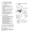
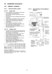
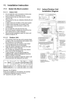
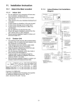
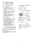
11. Installation Instruction 11.1 11.1.1 Select the Best Location 11.1.2 Indoor Unit Do not install the unit in excessive oil fume area such as kitchen, workshop and etc. There should not be any heat source or steam near the unit. There should not be any obstacles blocking the air circulation. A place where air circulation in the room is good. A place where drainage can be easily done. A place where noise prevention is taken into consideration. Do not install the unit near the door way. Ensure the spaces indicated by arrows from the wall, ceiling, fence or other obstacles. Mount with the lowest moving parts at least 8 ft (2.4 m) above floor or grade level. 16 Indoor/Outdoor Unit Installation Diagram 11.2 11.2.1 Indoor Unit How to Fix Installation Plate The mounting wall shall be strong and solid enough to prevent it from the vibration. The center of installation plate should be at more than at right and left of the wall. The distance from installation plate edge to ceiling should more than . From installation plate left edge to unit’s left side is . From installation plate right edge to unit’s right side is . B ○ : For left side piping, piping connection for liquid should be about from this line. : For left side piping, piping connection for gas should be about from this line. 1 2 11.2.2 Mount the installation plate on the wall with 5 screws or more (at least 5 screws). (If mounting the unit on the concrete wall, consider using anchor bolts.) o Always mount the installation plate horizontally by aligning the marking-off line with the thread and using a level gauge. Drill the piping plate hole with ø2 3/4" (ø70 mm) hole-core drill. o Line according to the left and right side of the installation plate. The meeting point of the extended line is the center of the hole. Another method is by putting measuring tape at position as shown in the diagram above. The hole center is obtained by measuring the distance namely 5 1/16" (128 mm) for left and right hole respectively. o Drill the piping hole at either the right or the left and the hole should be slightly slanting to the outdoor side. To Drill a Hole in the Wall and Install a Sleeve of Piping 1 2 3 Insert the piping sleeve to the hole. Fix the bushing to the sleeve. Cut the sleeve until it extrudes about 19/32" (15 mm) from the wall. 1 Finish by sealing the sleeve with putty or caulking compound at the final stage. 17 11.2.3 Indoor Unit Installation 11.2.3.1 For the right rear piping 11.2.3.2 For the right bottom piping 11.2.3.3 For the embedded piping (This can be used for left rear piping and bottom piping also.) 18 11.2.4 Connect the Cable to the Indoor Unit 1. The inside and outside connection cable can be connected without removing the front grille. 2. Unscrew the conduit cover and fix the conduit connector to conduit cover with lock nut, then secure it against chassis. 3. Connection cable between indoor unit and outdoor unit should be UL listed or CSA approved 4 conductor wires minimum AWG16 in accordance with local electric codes. o Ensure the colour of wires of outdoor unit and terminal number are the same as the indoor's respectively. o Earth lead wire shall be Yellow/Green (Y/G) in colour and shall be longer than other lead wires as shown in the figure for electrical safety in case of the slipping. 19 11.2.5 Wiring Stripping and connecting requirement 11.2.5.1 1 2 3 Cutting and flaring the piping Please cut using pipe cutter and then remove the burrs. Remove the burrs by using reamer. If burrs are not removed, gas leakage may be caused. Turn the piping end down to avoid the metal powder entering the pipe. Please make flare after inserting the flare nut onto the copper pipes. 20