1
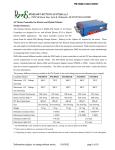
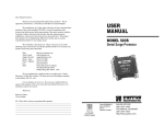
OPERATING INSTRUCTIONS
M3688
OMEGA
0701
SH SERIES
Air Heaters
MODEL NUMBERS
SH-73343
SH-73344
SH-73345
SH-73346
SH-73347
SH-73348
⇒ FOR SAFETY AND LONG HEATER LIFE, CAREFULLY READ THIS MANUAL BEFORE USE.
Description
Compact, safe and versatile heating unit for heating air or inert gas up to 1400°F. The SH-Series is available in
wattages from 6kW to 36kW, and can be use with compressed air or a regenerative blower. The SH heater is
designed for closed-loop temperature control, with a solid-state relay or phase angle fired SCR power control.
Sensors inside the heater sense both element temperature and inlet air temperature and limit heater voltage and
prevent element burnout if airflow is suddenly reduced. With this system, full power may safely be applied to the
system with zero airflow. If operated correctly, the heater element will operate continuously for 5000 hours or longer.
Specifications
•
•
•
•
•
•
•
Max. Static Pressure:
Max. Exit Air Temp:
Max. Inlet Air Temp:
Exit Connection:
Inlet Connection:
Control:
Over-Temp Circuit:
System (Heater
+ Over-Temp)
SH-73343
SH-73344
SH-73345
SH-73346
SH-73347
SH-73348
10 PSI
1400°F
130°F
1-1/2" NPT
1-1/4” NPT
Closed Loop: 4-20mADC or Pulsed DC (3-32V, etc.)
Dual-Input Limit Card mounted on a 6” x 3.15” x 1.6” deep snap track.
Mount track to control cabinet using two #8 mounting screws, drilled 5.63” O.C.
kW
Max. Volts
6
6
10
10
18
36
240-1 phase
480-3 phase
240-1 phase
480-3 phase
480-3 phase
480-3 phase
Max. Amp
Draw
25.0
7.2
41.7
12.0
21.7
43.4
Replacement
Element P/N
SH-73351
SH-73352
SH-73353
SH-73354
SH-73355
SH-73356
Safety
!
SHOCK HAZARD Only qualified individuals should install this heater and related controls. Follow all applicable
electrical codes and use proper wiring.
!
WARNING! Sensors are at or near line voltage. Use teflon jacketed, teflon insulated “K” thermocouple wire
to connect heater sensors to the over-temperature board.
!
BURN/FIRE/EXPLOSION HAZARD Do not use with or near explosive or reactive gases. Avoid contact with the
side, or exposure to the exit-end, during or soon after operation. DO NOT USE NEAR VOLATILE OR
COMBUSTIBLE MATERIALS.
Pa ge 1
OPERATING INSTRUCTIONS
OMEGA
Precautions
!
!
Use filtered air. Avoid grease, oil, or oil vapors, corrosive or reactive gases which will damage heater.
Use exposed junction type “K” thermocouple within one inch of the heater exit for good control.
Installation and Wiring
See attached drawings.
WARNING! Sensors are at or near line voltage. Use teflon jacketed, teflon insulated “K” thermocouple wire to
connect heater sensors to the over-temperature board.
1.
2.
Be sure heater is securely mounted.
Follow all applicable electrical codes when mounting and wiring heater and control components.
Operation
1.
2.
3.
4.
5.
Turn on air and set pressure or flow to desired operating level.
Turn on power to the over-temperature board.
Turn on power to the power controller.
Turn on power to the temperature controller.
Set desired temperature on temperature controller.
During operation, with steady-state airflow, the exit temperature should not vary more than a few degrees from set
point. Although the heater will not burn out with zero airflow, if the heater is operated in a vertical downward position
and an airflow of 100 SCFH or below is run through the heater, the inlet temperature of the heater will exceed 150°F
and the Over-temperature board will begin to limit power to the heater.
To Shut Down:
1.
2.
Turn off power to the temperature controller and the power controller.
Allow air to continue to flow for a minimum of 1 minute or until exit air temperature is 150°C or less for
safety. Continue airflow longer if hot equipment components present any potential hazard to personnel.
Turn off air to the system.
3.
Replacing Elements
Before replacing the element assembly, determine the cause of the element failure. Prior to powering the system
back up, make certain that the entire system is operating properly. Possible causes of element failure are:
1.
2.
3.
Normal end of Life
Failure in Control System
Mechanical Damage to System
REPLACEMENT PROCEDURE
1. Turn off power to the system. Follow lock-out/tag-out procedures.
2. Unscrew the 3 external housing screws and remove the stainless heater housing.
3. Unplug element from its socket and plug new element into the socket.
4. Slide the stainless heater housing back over the element and secure housing with the 3 external housing screws.
Performance Curves
The following curves show the maximum temperature performance of the SH-Series heater as measured by a “K”
type thermocouple located within 1” of heater exit. Use of other temperature measuring devices or varying the
distance of the measurement may cause different temperature readings. The heaters will not generate temperatures
greater than indicated on the graph in and if used correctly will maintain operating life in excess of 5000 hours.
P age 2
OPERATING INSTRUCTIONS
OMEGA
S H -S e r ie s M a x im u m P e r fo r m a n c e
(M e a s u re d b y " K " th e rm o c o u p le lo c a te d 1 " fro m h e a te r e x it w ith 7 0 ° F
in le t a ir)
Exit Temperature (° F)
1600
1400
1200
1000
800
6 KW
600
10 KW
400
18 KW
36 KW
200
0
0
1000
2000
3000
4000
5000
6000
7000
8000
A ir F lo w (S C F H )
N o te : T ru e a ir te m p e ra tu re is
a p p ro x . 1 0 0 ° F a b o v e lin e s in d ic a te d .
T h e rm o c o u p le re a d in g s te n d to b e lo w e r d u e
to th e rm a l m a s s /h e a t s in k e ffe c ts .
Warranty
Omega warrants that all products to be delivered hereunder will be free from defects in material and
workmanship at the time of delivery. Omega's obligation under this warranty shall be limited to (at its option)
repairing, replacing, or granting a credit at the prices invoiced at the time of shipment for any of said products.
This warranty shall not apply to any such products which shall have been repaired or altered, except by
Omega, or which shall have been subjected. Omega shall be liable under this warranty only if (A)
Omega receives notice of the alleged defect within sixty (60) days after the date of shipment; (B) the
adjustment procedure hereinafter provided is followed, and (C) such products are, to Omega’s
satisfaction, determined to be defective.
THE WARRANTY SET FORTH IN THE PRECEDING PARAGRAPH IS EXCLUSIVE AND IN LIEU OF ALL OTHER
WARRANTIES, EXPRESS OR IMPLIED, INCLUDING, WITHOUT LIMITATION, ANY IMPLIED WARRANTY OF
FITNESS FOR A PARTICULAR PURPOSE OR OF MERCHANTABILITY.
The information contained in this manual is based on data considered to be true and accurate. Reasonable
precautions for accuracy has been taken in the preparation of this manual, however Omega assumes no
responsibility for any omissions or errors, nor assumes any liability for damages that may result from the use of the
product in accordance with the information contained in this manual.
Please direct all warranty/repair requests or inquiries with the following information,
in writing:
(A)
(B)
(C)
Order number under which products were shipped
Model/Serial Number of product
Reason for rejection
PRODUCTS CANNOT BE RETURNED AUTHORIZATION.
Replacement, repair, or credit for products found to be defective will be made by the place of purchase. All products
found to be not defective will be returned to the Buyer; transportation charges collect or stored at Buyers expense.
Pa ge 3
OPERATING INSTRUCTIONS
WIRING DIAGRAM
MOUNTING DIMENSIONS
Pa ge 4
OMEGA