1
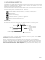
User's Guide http://www.omega.com e-mail: info @omega.com LDP-124 AND LDP-144 SERIES FOR TEMPERATURE OMEGAnet On-Line Service http://www.omega.com Internet e-mail [email protected] Servicing North America: USA : ISO 9001 Certified Canada : One Omega drive, Box 4047 Stamford, CT 06907-0047 Tel : (203) 359-1660 e-mail : [email protected] 976 Bergar Laval (Quebec) H7L 5A1 Tel : (514) 856-6928 e-mail : [email protected] Fax : (203) 359 7700 Fax : (514) 856-6886 For immediate technical or application assistance: USA and Canada : Mexico and Latin America : Sales Service : 1-800-826-6342 / 1-800-TC-OMEGASM Customer Service : 1-800-622-2378 / 1-800-622-BESTSM Engineering Service : 1-800-872-9436 / 1-800-USA-WHENSM Telex : 996404 EASYLINK : 62968934 CABLE : OMEGA Tel : (95) 800-826-6342 En Español : (203) 359-7803 Fax : (95) 203-359-7807 e-mail : [email protected] Servicing Europe: Benelux: Czech Republic : France : Germany/Austria : United Kingdom : ISO 9002 Certified Postbus 8034, 1180 LA Amstelveen, The Netherlands Tel : (31) 20 6418405 Fax : (31) 20 6434643 Toll Free in Benelux : 0800 0993344 e-mail : [email protected] ul. Rude armady 1868, 733 01 Karvina-Hranice Tel : 420 (69) 6311899 Fax : 420 (69) 6311114 Toll Free : 0800-1-66342 e-mail : [email protected] 9, rue Denis Pappin, 78190 Trappes Tel : (33) 130-621-400 Fax : (33) 130-699-120 Toll Free in France : 0800-4-06342 e-mail : [email protected] Daimlerstrasse 26, D-75392 Deckenpfronn, Germany tel : 49 (07056) 3017 Fax : 49 (07056) 8540 Toll Free in Germany : 0130 11 21 66 e-mail : [email protected] One Omega Drive, River Bend Thecnology Centre Northbank, Irlam, Manchester M44 5EX, England Tel : 44 (161) 777-6611 Fax : 44 (161) 777-6622 Toll Free in the United Kingdom : 0800-488-488 e-mail : [email protected] It is the policy of OMEGA to comply with all worldwide safety and EMC/EMI regulations that apply. OMEGA is constantly pursuing certification of its products to the European New Approach Directives. OMEGA will add the CE mark to every appropriate device upon certification. The information contained in this document is believed to be correct, but OMEGA Engineering, Inc. accepts no liability for any errors it contains, and reserves the right to alter specifications without notice. WARNING : These products are not designed for use in, and should not be user for, patient connected applications. Page :1 CONTENTS DESCRIPTION SECTION PAGE =========================================================================== IMPORTANT SAFETY CONSIDERATIONS 1 3 UNPACKING AND INSPECTION 2 4 MAIN FEATURES 3 5 MODELS 4 6 LDP-1X4-MX, TEMPERATURE INDICATOR FOR RTD SENSOR (PT-100) LDP-1X4-J1,J2 TEMPERATURE INDICATOR FOR THERMOCOUPLE "J" 6 6 LDP-1X4-K1,K2 TEMPERATURE INDICATOR FOR THERMOCOUPLE "K" 6 LDP-1X4-T1,T2 TEMPERATURE INDICATOR FOR THERMOCOUPLE "T" 6 LDP-1X4-E1,E2 TEMPERATURE INDICATOR FOR THERMOCOUPLE "E" 6 LDP-1X4-S1,S2 TEMPERATURE INDICATOR FOR THERMOCOUPLE "S" 6 LDP-1X4-R1,R2 TEMPERATURE INDICATOR FOR THERMOCOUPLE "R" LDP-1X4-L1, TEMPERATURE INDICATOR FOR THERMOCOUPLE "L" 6 6 GENERAL SPECIFICATIONS 5 7 FRONT VIEW, DESCRIPTION 6 7 REAR VIEW, DESCRIPTION 7 7 8 8 WIRING POWER SUPPLY, RECOMMENDED WIRING. 8.1 8 FUSES. SENSOR CONNECTIONS FOR MODEL MX. 8.2 8.3 8 8 SENSOR CONNECTIONS FOR MODELS J1,K1,T1,E1,S1,R1, & L1. 8.4 8 9 9.1 9.2 9 9 9 TEMPERATURE RANGES MODEL MX. SENSOR TYPE RTD (PT-100) MODELS J1,J2,K1,K2,T1,T2,E1,E2,S1,S2,R1,R2 & L1, SENSOR TYPE THERMOCOUPLE SIGNAL CONDITIONERS 10 9 SIGNAL CONDITIONER FOR RTD SENSOR 10.1 9 SIGNAL CONDITIONERS FOR THERMOCOUPLE SENSORS 10.2 9 11 11.1 11.2 10 10 10 INSTALLATION 12 11 MECHANICAL DIMENSIONS 13 11 ADJUSTMENT AND CALIBRATION PROCEDURE RTD MODEL THERMOCOUPLE MODELS WARRANTY 12 OTHER PRODUCTS 13 Page : 2 1.- IMPORTANT SAFETY CONSIDERATIONS INSTALLATION SAFETY CONSIDERATIONS PRESCRIPTIONS.- PRECAUTIONS.The installation and the future use of this unit must be done by suitable qualified personnel. The unit has not AC (mains) switch, it will be in operation as soon as power is connected. The installation must incorporate an external main switch. The unit has a protection fuse incorporated on the AC socket, if it is necessary to change or replace, use the time-lag fuse according IEC 127/2 and the values indicated below. 200 mA when the unit is operating at 230 Vac 400 mA when the unit is operating at 115 Vac. Install also the necessary devices to protect the operator and the process when using the unit to control a machine or process where injury to personnel or damage to equipment or process, may occur as a result of failure of the unit. See paragraph 8, WIRING. SAFETY PRESCRIPTIONS.The unit has been designed and tested under EN 61010-1 rules and is delivered in good condition. This operator's manual contains useful information for electrical connections. Do not make wiring signal changes or connections when power is applied to the unit. Make signal connections before power is applied and, if reconnection is required, disconnect the AC (mains) power before such wiring is attempted. Install the unit in places with a good ventilation to avoid the excessive heating. And far from electrical noise source or magnetic field generators such as power relays, electrical motors, speed controls etc... The unit cannot be installed in open places. Do not use until the installation is finished. POWER SUPPLY.The power supply must be connected to the adequate terminals (see the connection instructions). The characteristics of the power supply are showed on the label on the rear part. Please make sure that the unit is correctly connected to a power supply of the correct voltage and frequency. Do not use other power supply otherwise permanent damage may be caused to the unit. Do not connect the unit to power sources heavily loaded or to circuits which power loads in cycle ON-OFF or to circuits which power inductive loads. SIGNAL WIRING.Certain considerations must be given when install the signal input and control wires. If the wires are longs can act like an antenna and introduce the electrical noise to the unit, therefore : Do not install the signal input wires in the same conduit with power lines, heaters, solenoids, SCR controls etc....and always far from these elements. When shielded wires are used, connect the shield to the common terminal and leave unconnected the other end of the shield and do not connect to the machine ground. Page : 3 Before starting any operation of adjustment, replacement, maintenance or repair, the unit must be disconnected from any kind of power supply. Keep the unit clean , to assure good functioning and performance. Use for it a clean and humid rag. Do not use for the frontal lens abrasive products, solvents, alcohol, etc... because its transparence could be damaged and this may cause difficulty for a correct vision of the reading. To prevent electrical or fire hazard, do not expose the unit to excessive moisture. Do not operate the unit in the presence of flammable gases or fumes, such as environment constitutes a definite safety hazard. The unit is designed to be mounted in a metal panel. If the unit shows signs of damage, or is not able to show the expected measures, or has been stored in a bad conditions or a protection failure can occur, then do not attempt to operate and keep the unit out of service. IN CASE OF FIRE 1.- Disconnect the unit from the power supply. 2.- Give the alarm according to the local rules. 3.- Switch off all the air conditioning devices. 4.- Attack the fire with carbonic snow, do not use water in any case. WARNING : In closed areas do not use systems with vaporized liquids. CONNECTIONS All wiring connections are made using push-in cable connectors. There is a separate connector block for power supply and input signals. Please make sure that each connector block is connected on the adequate place. The wire cross section recommended for signal inputs is 1 mm2 and for power supply 2.5 mm 2. PANEL MOUNTING Verify that the panel cut-out is correctly according to the dimensions indicated on page 11 with a minimum depth of 150 mm. (5.9"). Install the fixation pieces in the lateral guides of the unit by its rear part and then turn the screw firmly against the panel, until the unit is totally hold on. See paragraph 12 on page 11. 2.- UNPACKING AND INSPECTION It is advisable to do a detailed reading of this Manual before mounting the instrument. This Operator's Manual contains all the technical specifications : electricals as well as mechanics, both necessary to do a correct installation and also a good use of the instrument. At the same time the user will acquire the knowledge needed to obtain the best performances of the product. Check that inside the present cardboard box, there are the following : 1 Instrument Model LDP-1X4-MX, J1,J2, K1,K2, T1,T2, E1,E2, S1,S2, R1,R2 & L1. 1 Operator's Manual. 1 Connector for Power Supply. 1 Screw-clamp connectors, 4 pins female for signal inputs. 2 Pieces for fixing the unit against the panel. REFERENCE KEY All models have a label on the rear part with their references printed on the following format : LDP- 1X4-XX-X-X Basic serie Digit size 2 = 57 mm (2.3") 4 = 100 mm (4") Number of digits 4 = 4 digits Power supply 0 = 230 Vac 50/60 Hz. 1 = 115 Vac 50/60 Hz. Display color R = Red G = Green Model reference If there are some doubts or inquiries about the present instrument, please contact OMEGA ENGINEERING´S customer service department. When the shipment arrives remove the Packing List and verify that you have received all equipment. Then inspect the box and the instrument, and if there is evidence of damage caused by bad handling during the transport, it is advisable to make a careful inspection of all damages making a note of all of them and to pass on this information directly to the Transport Company. If this occurs but with insured material, ask the Transport Company for instructions about submitting a claim Page : 4 3.- MAIN FEATURES On this paragraph is detailed the main features for every one of the series which are the following : Instruments of four digits plus polarity (only minus) to show temperature using the signal generated by sensors type RTD (PT-100 (0.00385), model MX) or Thermocouples (models J1,J2, K1,K2, T1,T2, E1,E2, S1,S2, R1,R2 and L1). All instruments of these two series also has circuitry to linearize the sensor signal and the value displayed is proportional to the measured temperature in °C or °F for all range corresponding to every sensor. See paragraph 9, page 9. Serie LDP-124-XX : 4 digits type LED, seven segments, red or green colour with 57 mm (2.3") height and minus sign for polarity. Serie LDP-144-XX : 4 digits type LED, seven segments, red or green colour with 100 mm (4") height and minus sign for polarity. The complete reference for each instrument is obtained replacing the XX by the corresponding reference of each temperature sensor. The common features for all series are the following: MECHANICAL.Housed in a rugged extruded aluminium profile housing for panel mounting or free standing. Finished in anodized black colour. The frontal lens is mounted with a special rubber profile which provides the front part of the unit with an IP-65 protection. CONNECTIONS.Connections for Signal Inputs are made using one screw-clamp connector of four terminals located on the rear part of the unit. The recommended wire cross section for RTD sensors is 1 mm2. For thermocouples must be used the compensate wire adequate for each thermocouple. Connection for Power Supply uses a push-in cable connector with 2 terminals for power and 1 terminal for earth. The fuse is located in the Power Supply socket, as well as the spare fuse. SENSOR BREAK DETECTION.The linearizing circuits for RTD and for thermocouple sensors are provided with an special control to detect when the sensor is broken or when the circuit sensor is opened. If it occurs then the display starts to flash. AUTOMATIC COMPENSATION.The variation resistance of the RTD sensors is in function of the temperature measured. To avoid errors due to the lead wire resistance the LDP-1X4-MX uses a 3-wire measurement, which compensates the lead wire resistance. However 2-wire sensors can be used. See wiring connections, paragraph 8.3 page 8. The maximum resistance allowable is 10 Ω. The thermocouple sensors generate a voltage produced by the junction of two metals with a different characteristics. Therefore use the specific compensation wires for each model of thermocouple on the measurement circuit to avoid create a new junction which should generate a small signal and it should be added to the signal generated by the thermocouple sensor. All instruments for thermocouple sensors are provided with a circuitry for Cold-Junction compensation. Page : 5 4.- MODELS LDP-1X4-MX Temperature indicator for RTD sensor type PT-100 (100 Ω at 0 °C Alpha = 0.00385). This model uses the 3-wire measurement, which compensates thelead wire resistance. However 2-wire sensors can be used too. See wiring connections. The sensor signal is linearized according to IEC 751-DIN 43760. The maximum excitation current is @1 mA. LDP-1X4-J1,J2 Temperature indicator for thermocouple sensor type J (Fe-Kons). Provided with automatic Cold-junction compensation and open measure circuit detection. The sensor signal is linearized according to IEC 584; IPTS 1968; ANSI/MC96.1; DIN 43710. LDP-1X4-K1,K2 Temperature indicator for thermocouple sensor type K (NiCr-NiAl). Provided with automatic Cold-junction compensation and open measure circuit detection. The sensor signal is linearized according to IEC 584; IPTS 1968; ANSI/MC96.1; DIN 43710. LDP-1X4-T1,T2 Temperature indicator for thermocouple sensor type T (Cu-CuNi). Provided with automatic Cold-junction compensation and open measure circuit detection. The sensor signal is linearized according to IEC 584; IPTS 1968; ANSI/MC96.1; DIN 43710. LDP-1X4-E1,E2 Temperature indicator for thermocouple sensor type E (NiCr-CuNi). Provided with automatic Cold-junction compensation and open measure circuit detection. The sensor signal is linearized according to IEC 584; IPTS 1968; ANSI/MC96.1; DIN 43710. LDP-1X4-S1,S2 Temperature indicator for thermocouple sensor type S (Pt-PtRh 10%). Provided with automatic Cold-junction compensation and open measure circuit detection. The sensor signal is linearized according to IEC 584; IPTS 1968; ANSI/MC96.1; DIN 43710. LDP-1X4-R1,R2 Temperature indicator for thermocouple sensor type R (Pt-PtRh 13%). Provided with automatic Cold-junction compensation and open measure circuit detection. The sensor signal is linearized according to IEC 584; IPTS 1968; ANSI/MC96.1; DIN 43710. LDP-1X4-L1 Temperature indicator for thermocouple sensor type L or DIN J (Fe-Kons). Provided with automatic Cold-junction compensation and open measure circuit detection. The sensor signal is linearized according to DIN 43710. Each model also has a circuitry to linearize the sensor signal,and the value displayed is proportional to the measured temperature in °C or °F. Page : 6 5.- GENERAL SPECIFICATIONS DISPLAY ENVIRONMENTAL TYPE . . . . . . . . . . . . . . . . . . . . . . . . . 4 digits, 7 segments, red or green LED. HEIGHT DIGIT . . . . . . . . . . . . . . . . . . 57 mm. (2.3") or 100 mm. (4"). RANGE . . . . . . . . . . . . . . . . . . . . . . . -9999 a 9999 POLARITY . . . . . . . . . . . . . . . . . . . . . Minus only (-). OVERRANGE . . . . . . . . . . . . . . . . . . Display flashing. DECIMAL POINT . . . . . . . . . . . . . . . . Models M1& M3. OPERATING TEMPERATURE . . STORAGE TEMPERATURE . . . . RELATIVE HUMIDITY . . . . . . . . PROTECTION . . . . . . . . . . . . . . . ANALOG-TO-DIGITAL CONVERSION INPUT CONFIGURATION . . . . . . . . TECHNIQUE . . . . . . . . . . . . . . . . . . . . POLARITY . . . . . . . . . . . . . . . . . . . . . SIGNAL INTEGRATION PERIOD . . . . READ RATE . . . . . . . . . . . . . . . . . . . OSCILLATOR . . . . . . . . . . . . . . . . . . Single ended. Dual slope, average value. Automatic, only minus sign. 100 ms. 2.5/s. 400 KHz. quartz crystal. 0 to +50 ºC (32 to 122 ºF). -20 to +85 º C (-4 to 185 ºF). 0 to 85 % not condensed. IP65. (Front part only). MECHANICAL DIMENSIONS . . . . . . . . . . . . . . . PANEL CUT OUT . . . . . . . . . . . . DEPTH . . . . . . . . . . . . . . . . . . . . WEIGHT . . . . . . . . . . . . . . . . . . . CASE MATERIAL . . . . . . . . . . . FINISHED . . . . . . . . . . . . . . . . . . See table in page 11. See table in page 11. See table in page 11. See table in page 11. Aluminium extruded. Anodized, black colour. ELECTRICAL STANDARD POWER SUPPLY . 115 Vac. ±10% 50 / 60 Hz. (Optionally 230 Vac) POWER CONSUMPTION . . . . . . See table in page 11. 6.- FRONT VIEW, for both series Polarity indicator Decimal point. Model M1 & M3 7.- REAR VIEW, for both series Attaching screws Signal input connector D C B A Power Supply Vac + Earth, fuse and spare fuse. Page : 7 8.- WIRING 8.1.- POWER SUPPLY, RECOMMENDED WIRING POWER SUPPLY 115 Vac (230 Vac Optional). Power switch FUSE and spare fuse. 8.2.- PROTECTION FUSES The unit has a protection fuse located on the power supply socket. If this fuse must be replaced or changed because the power supply is changed, use the time-lag fuse according to IEC 127/2 with the values indicated on the table. Power Supply Fuse value 230 Vac 115 Vac 0.2 A 0.4 A 8.3.- SENSOR CONNECTIONS FOR MODEL: MX. C PT-100 Signal input connector. B A 3-wires connection. PT-100 D 2-wires connection. Do not forget to link terminal A to terminal C. 8.4.- SENSOR CONNECTIONS FOR MODELS: J1,J2,K1,K2,T1,T2,E1,E2,S1,S2,R1,R2 & L1. D Signal input connector. C B A + Thermocouple _ Page : 8 9.- TEMPERATURE RANGES 9.1.- MODEL M1, M2 & M3. RTD SENSOR (PT-100) MODEL TEMPERATURE RANGE ACCURACY (±1 COUNT) RESOLUTION 0.1 °C M1 - 100.0 to + 650.0 °C ± 0.4 % M2 -300 to 1526 °F ± 0.4 % 1 °F M3 - 200.0 to 999.9 °F ± 0.2 % 0.1 °F MAXIMUM COMPENSATION 10 Ω Allowable error in negative range due to the lead wire resistance : 0.2°C/Ω or 0.4°F/Ω 9.2.- MODELS: J1,J2,K1,K2,T1,T2, E1,E2,S1,S2,R1,R2 & L1. THERMOCOUPLE SENSORS MODEL TEMPERATURE RANGE ACCURACY ± 1 count MODEL TEMPERATURE RANGE ACCURACY ± 1 count RESOLUTION J1 - 50 to + 600°C ± 0.5 % J2 - 40 to 1000°F ± 0.5 % 1°C / 1°F K1 0 to + 1250°C ± 0.5 % K2 32 to 2250°F ± 0.5 % 1°C / 1°F T1 - 50 to + 400°C ± 0.5 % T2 - 40 to 750°F ±1% 1°C / 1°F E1 0 to + 650°C ± 0.2 % E2 32 to 1200°F ± 0.3 % 1°C / 1°F S1 + 970 to + 1750°C ± 0.1 % S2 1775 to 3150°F ± 0.2 % 1°C / 1°F R1 + 1000 to + 1750°C ± 0.2 % R2 1850 to 3150°F ± 0.3 % 1°C / 1°F L1 - 50 to + 600°C ± 0.5 % AMBIENT TEMP. COMPENSATION ALL MODELS 0°C to + 50°C 32°F to 122°F 1°C 10.- SIGNAL CONDITIONERS. Control board. Horizontal position in instruments serie LDP-124 Vertical position in instruments serie LDP-144 The control board contains the Analog/Digital converter, the Signal Conditioner and other components. The function of the Signal Conditioner is amplifier and make the linearisation of the signal received from the sensor and there is one Signal Conditioner for every model of RTD or Thermocouple sensor. The trimmers for Span and Zero are also located on the Signal Conditioner. Use these trimmers only for calibration procedure. Components view Signal conditioner Components side. Decimal Point Selector JG JE JG = XXX.X JE = X.XXX JF = XX.XX JF 10.1.- SIGNAL CONDITIONER FOR RTD SENSOR PT1 Signal Instrument Conditioner Reference Reference MB-21 MB-21-F2 MB-21-F3 LDP-1X4-M1 * LDP-1X4-M2 LDP-1X4-M3 * ZERO adjust. COMPONENTS SIDE C B PT2 SPAN adjust. A * Jumper JG located on Decimal Point Selector must be closed. 10.2.- SIGNAL CONDITIONERS FOR THERMOCOUPLE SENSORS Signal Conditioner Reference MB-22 or 22F MB-23 or 23F MB-24 or 24F MB-25 or 25F MB-26 or 26F MB-27 or 27F MB-28 Page : 9 Instrument Reference LDP-1X4-J1,J2 LDP-1X4-K1,K2 LDP-1X4-T1,T2 LDP-1X4-E1,E2 LDP-1X4-S1,S2 LDP-1X4-R1,R2 LDP-1X4-L1 PT2. SPAN adjust. COMPONENTS SIDE C B PT1. ZERO adjust A All jumpers on Decimal Point Selector must be opened. 11.- ADJUSTMENT AND CALIBRATION PROCEDURE 11.1.- RTD MODELS A decade box or RTD simulator is required. 1.- Check that the instrument is not powered. 2.- Connect the RTD simulator or decade box to the signal input connector (See paragraph 8.3). 3.- Remove the rear cover taking off all the screws to obtain access to the control board. (See page 7 paragraph 7). 4.- Power up the instrument with the appropriate power supply and wait until 3 minutes before to start the adjust. 5.- Adjust the RTD simulator to generate the low signal indicated in TABLE-A. 6.- Display must shows the DISPLAY value indicated in TABLE-A, if not turn the trimmer PT1 located on the Signal Conditioner (See paragraph 10.1) until display shows the DISPLAY value. 7.- Adjust the RTD simulator to generate the high signal, see TABLE-B. 8.- Display must shows the DISPLAY value indicated in TABLE-B, if not turn the trimmer PT2 located on the Signal Conditioner (See paragraph 10.1) until display shows the DISPLAY value. 9.- Repeat steps 5 to 8 until the two values are correct. 10.- Check that the linearity remains correct, testing some other points of the range. 11.2.- THERMOCOUPLE MODELS A Thermocouple simulator with Cold Junction compensation is required. 1.- Check that the instrument is not powered. 2.- Connect the Thermocouple simulator to the signal input connector (See paragraph 8.4). 3.- Remove the rear cover taking off all the screws to obtain access to the control board. (See page 7 paragraph 7). 4.- Power up the instrument with the appropriate power supply and wait until 3 minutes before to start the adjust. 5.- Adjust the Thermocouple simulator to generate the low signal indicated in TABLE-A. 6.- Display must shows the DISPLAY value indicated in TABLE-A, if not turn the trimmer PT1located on the Signal Conditioner (See paragraph 10.2) until display shows te correct value. 7.- Adjust the Thermocouple simulator to generate the high signal indicated in TABLE-B. 8.- Display must shows the DISPLAY value, if not turn the trimmer PT2 located on the Signal Conditioner (See paragraph 10.2) until obtain the DISPLAY value. 9.- Repeat steps 5 to 8 until the low and the high signals are correct. 10.- Check that the linearity remains correct, testing some other points of the range. TABLE - A TABLE - B MODEL LOW SIGNAL DISPLAY MODEL M1 M2 M3 J1 J2 K1 K2 T1 T2 E1 E2 R1 R2 S1 S2 L1 0°C 0°F 0°F 0°C 32°F 0°C 32°F 0°C 0°F 0°C 32°F 300°C 32°F 200°C 32°F 0°C 000.0 0000 000.0 0000 0032 0000 0032 0000 0000 0000 0032 0300 0032 0200 0032 0000 M1 M2 M3 J1 J2 K1 K2 T1 T2 E1 E2 R1 R2 S1 S2 L1 HIGH SIGNAL 600°C 500°F 200°F 600°C 1000°F 1200°C 2000°F 400°C 400°F 600°C 1200°F 1700°C 3100°F 1700°C 3100°F 600°C DISPLAY 600.0 0500 200.0 0600 1000 1200 2000 0400 0400 0600 1200 1700 3100 1700 3100 0600 Page : 10 12.- INSTALLATION 1.- Prepare a panel cut-out with the dimensions indicated on paragraph 13. 2.- Slide the instrument (1) into the cut-out. 3.- Slide the two fixation pieces (3) with T shape by both lateral sides of the instrument, such as it is shown on the drawing below. 4.- Turn the screw bolt until it is pressed firmly against the panel (4) and the instrument (1) remains totally fixed. 5.- The front part of the instrument has the necessary elements to provide an IP 65 protection. If the panel where this instrument must be installed, it must to comply some protection standards against water splashes, then a rubber profile must be installed with a rectangular or round shape (5) on the place indicated and shown on the drawing below. 1 5 4 2 3 13.- MECHANICAL DIMENSIONS mm (inches) Aluminium back plate C PANEL CUT-OUT 123456789012345678901234567 123456789012345678901234567 123456789012345678901234567 123456789012345678901234567 123456789012345678901234567 123456789012345678901234567 123456789012345678901234567 123456789012345678901234567 E 123456789012345678901234567 123456789012345678901234567 123456789012345678901234567 123456789012345678901234567 D 123456789012345678901234567 123456789012345678901234567 123456789012345678901234567 123456789012345678901234567 B Panel thickness : Max. 14 (0.55) Min. 2.5 (0.10) A Anti-Glare lens DIMENSIONS PANEL CUT-OUT Digits Height A B C 4 4 57 (2.3) 100 (4) 264 (10.4) 480 (18.9) 120 (4.75) 180 (7.09) 112 (4.41) 112 (4.41) D 256 (10.07) 472 (18.58) WEIGHT POWER 2.3 Kg (5 lbs) 5 Kg (11 lbs) 6 VA 12 VA E 112 (4.4) 172 (6.77) Dimensions in mm. Values in brackets are inches or pounds. Add 27 mm (1.1) to the dimension C for power connector. Page : 11 WARRANTY/DISCLAIMER OMEGA ENGINEERING, INC. warrants this unit to be free of defects in materials and workmanship for a period of 13 months from date of purchase. OMEGA warranty adds an additional one (1) month grace period to the normal one (1) year product warranty to cover handling and shipping time. This ensures that OMEGA’s customers receive maximum coverage on each product. If the unit malfunction, it must be returned to the factory for evaluation. OMEGA’s Customer Service Department will issue an Authorized Return (AR) number immediately upon phone or written request. Upon examination by OMEGA, if the unit is found to be defective it will be repaired or replaced at no charge. OMEGA’s WARRANTY does not apply to defects resulting from any action of the purchaser, including but not limited to mishandling, improper interfacing, operation outside of design limits, improper repair, or unauthorized modification. This WARRANTY is VOID if the unit shows evidence of having been tampered with or shows evidence of having been damaged as a result of excessive corrosion; or current, heat, moisture or vibration; improper specification; misapplication; misuse or other operating conditions outside of OMEGA’s control. Components which wear are not warranted, including but not limited to contact points, fuses and triacs. OMEGA is pleased to offer suggestions on the use of its various products. However OMEGA neither assumes responsibility for any omissions or errors nor assumes liability for any damages that result from the use of its products in accordance with information provided by OMEGA, either verbal or written. OMEGA warrants only that the parts manufactured by it will be as specified and free of defects. OMEGA MAKES NO OTHER WARRANTIES OR REPRESENTATIONS OF ANY KIND WHATSOEVER, EXPRESS OR IMPLIED, EXCEPT THAT OF TITLE, AND ALL IMPLIED WARRANTIES INCLUDING ANY WARRANTY OF MERCHANTABILITY AND FITNESS FOR A PARTICULAR PURPOSE ARE HEREBY DISCLAIMED. LIMITATION OF LIABILITY: The remedies of purchaser set forth herein are exclusive, and the total liability of OMEGA with respect to this order, whether based on contract, warranty, negligence, indemnification, strict liability or otherwise, shall not exceed the purchase price of the component upon which liability is based. In no event shall OMEGA be liable for consequential, incidental or special damages. CONDITIONS: Equipment sold by OMEGA is not intended to be used, nor shall it be used: (1) as a “Basic Component” under 10 CFR 21 (NRC), used in or with any nuclear installation or activity; or (2) in medical applications or used on humans. Should any Product(s) be used in or with any nuclear installation or activity, medical application, used on humans, or misused in any way. OMEGA assumes no responsibility as set forth in our basic WARRANTY/DISCLAIMER language, and, additionally, purchaser will indemnify OMEGA and hold OMEGA harmless from any liability or damage whatsoever arising out of the use of the Product(s) in such a manner. RETURN REQUESTS/INQUIRIES Direct all warranty and repair requests/inquiries to the OMEGA Customer Service Department. BEFORE RETURNING ANY PRODUCT(S) TO OMEGA, PURCHASER MUST OBTAIN AN AUTHORIZED RETURN (AR) NUMBER FROM OMEGAS’S CUSTOMER SERVICE DEPARTMENT (IN ORDER TO AVOID PROCESSING DELAYS). The assigned AR number should then be marked on the outside of the package and on any correspondence. The purchaser is responsible for shipping charges, freight, insurance and proper packaging to prevent breakage in transit. FOR WARRANTY RETURNS, please have the following information available BEFORE contacting OMEGA: 1. Purchase Order number under which the product was PURCHASED, 2. Model and serial number of the product under warranty, and 3. Repair instructions and/or specific problems relative to the product. FOR NON-WARRANTY REPAIRS, consult OMEGA for current repair charges. Have the following information available BEFORE contacting OMEGA: 1. Purchase Order number to cover the COST of the repair, 2. Model and serial number of the product, and 3. Repair instructions and/or specific problems relative to the product. OMEGA’s policy is to make running changes, not model changes, whenever an improvement is possible. This affords our customers the latest in technology and engineering. OMEGA is a registered trademark of OMEGA ENGINEERING, INC. © Copyright 1998 OMEGA ENGINEERING, INC. All rights reserved. This document may not be copied, photocopied, reproduced, translated, or reduced to any electronic medium or machine-readable form, in whole or in part, without prior written consent of OMEGA ENGINEERING, INC. Page : 12 Where Do I Find Everything I Need for Process Measurement and Control? OMEGA...Of Course! TEMPERATURE ; ; ; ; ; Thermocouple, RTD & Thermistor Probes, Connectors, Panels & Assemblies Wire: Thermocouple, RTD & Thermistor Calibrators & Ice Point References Recorders, Controllers & Process Monitors Infrared Pyrometers PRESSURE, STRAIN AND FORCE ; ; ; ; Transducers & Strain Gauges Load Cells & Pressure Gauges Displacement Transducers Instrumentation & Accessories FLOW/LEVEL ; ; ; ; Rotameters, Gas Mass Flowmeters & Flow Computers Air Velocity Indicators Turbine/Paddlewheel Systems Totalizers & Batch Controllers pH/CONDUCTIVITY ; ; ; ; pH Electrodes, Testers & Accessories Benchtop/Laboratory Meters Controllers, Calibrators, Simulators & Pumps Industrial pH & Conductivity Equipment DATA ACQUISITION ; ; ; ; ; Data Acquisition & Engineering Software Communications-Based Acquisition Systems Plug-in Cards for Apple, IBM & Compatibles Datalogging Systems Recorders, Printers & Plotters HEATERS ; ; ; ; ; Heating Cable Cartridge & Strip Heaters Immersion & Band Heaters Flexible Heaters Laboratory Heaters ENVIRONMENTAL MONITORING AND CONTROL ; ; ; ; ; ; Page : 13 Metering & Control Instrumentation Refractometers Pumps & Tubing Air, Soil & Water Monitors Industrial Water & Wastewater Treatment pH, Conductivity & Dissolved Oxygen Instruments M3191 / 1298