1
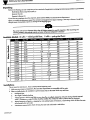
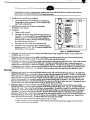
0 S&es
@fE Heav Duty Flowmeters
I
@IbL’
Operator’s Manual
FL900 Series Heavy Duty Flowmekws
Y___
,.
--
Unpack ing
Remove the Packing List and verify that you have received all equipment, including the
following (quantities in parentheses):
FL900 Series Heavy Duty Fiowmeter (1)
Extractor Tool (1)
Operator ’s Manual (1)
If you have any questions about the shipment, please call the OMEGA Customer Service Department.
When you receive the shipment, inspect the container and equipment for signs of damage.
Note any evidence of rough handling in transit. Immediately report any damage to the shipping agent.
The carrier will not honor damage claims unless all
shipping material is saved for inspection.
removing contents, save packing material and carton in the event reshipment is necessary.
Ava ilab le Mode ls (G
suffix - ribbed-guided floats;
P suffix -
After examining and
pole-guided floats)
FWOlG
0.64
-
7
1 /r
300
20
20 ”
FL902G
2.25
-
41
l/2 ”
300
20
20 ”
R903G
5.20
-
18
1’
250
20
20 ”
FL904G
12.60
-
13
1’
250
20
20
F1904P
34.50
-
110.
1’
250
20
20 ”
fWO6G
10.00
-
6
l-1/2 ”
150
30
25 ”
FwO6P
33.60
-
24
l-1/2 ”
150
30
25 ”
Fl.908G
65.00
-
30
2”
125
30
25 ”
FWO8P
132.00
-
60
2”
125
30
25 ”
FL91OG
-
2. 7
-
l/2 ”
30 0
20
20
FL911G
-
10.2
-
1/r
30 0
20
20 ”
1”
25 0
20
20 ”
FL91 2G
-
20.8
-
FL913P
-
98.5
-
FL915G
-
41 .o
FL915P
-
101.5
FL917G
-
59. 0
FL917P
-
350.0
l/2 ”
25 0
20
20 ”
l-1/2 ”
150
30
25 ”
-
l-1/2 ”
150
30
25 ”
-
2”
125
30
25 ”
-
2@
125
30
25 ”
Installations
This is important information. Read carefully before beginning work.
1. Make sure your pressure, temperature, fluid and other requirements are compatible with the meter.
2.
Select a suitable location for installation to prevent excess stress on the meter which may result
a.
Misaligned pipe.
b.
The weight of related plumbing.
C.
CJS0595MAl29A
from:
“Water Hammer ” which is most likely to occur when flow is suddenly stopped as with quick closing solenoid operated
valves. (it necessary, a surge chamber should be installed. This will also be useful in pressure start-up situations.)
d.
Thermal expansion of liquid in a stagnated or valve isolated system.
to be drained when not in use.)
e.
Instantaneous pressurization which will stress the meter and could result in tube failure.
(IF necessary, install valving which will allow the meter
In closed thermal transfer or cooling systems,
install the meter in the cool
and contraction and possible fluid leaks at the threaded connections.
3.
side of the line to minimize meter
expansion
Handle the meter carefully during installation.
a.
Use an appropriate amount of Teflon tape on external
threads before making connections. Do not use paste or stick
type thread sealing products.
4.
Install the meter vertically with
No piping runs are required.
5.
Connections:
pipe
the inlet port at the bottom.
a.
Fittings are fully rotatable.
b.
Flowmeters with stainless fittings hove dual ports (vertical and
horizontal). It is recommended that horizontal fittings be used
whenever practical. This will allow float stops and float (or
Roar and guide assembly) to be easily removed from the tube
for in-place cleaning (see Figure 1).
C.
d.
e
0
?
?
?
m
Flowmeters with plastic fittings have vertical ports only.
Flowmeters used in liquid service above 100 GPM should be
plumbed vertically (2 ” NPT). Th is will create less restriction and
provide optimum meter operation.
Figurm 1. Installation Diagram
6.
Flowmeters with stainless steel fittings will support
misaligned pipe are not factors.
7.
Flowmeters with plastic fittings must be installed so that fittings are not made to support any part of the associated plumbing.
Clamps mounted to a bulkhead or panel can be used to hold the meter securely at both ends.
8.
Flowmeters used in gas service should have suitable valves plumbed in at the inlet and outlet of the meter. These valves should be
no more than 1 - l/2 pipe diometers from the meter ports. The valve at the outlet should be used to create back pressure as
required to prevent floot bounce. It should be set initially and then left alone. The inlet valve should be used
for throttling purposes. Depending on the installation, valves may not be essential, but they are most useful in many installations. Remember to get a
correct reading of flow in gas service.
It is important to know the pressure right at the outlet of the meter (before the valve).
Cleaning
Several feet of pipe as long as significant vibration or stress resulting from
1.
If the tube is plain taper (has a pole-guided float) thread the extractor tool onto the threaded guide extension in the outlet fitting.
Remove the float stop retainers, and carefully withdraw the float and guide assembly from the tube. The tube is now fully accessible for cleaning with a bottle brush and an appropriate mild soap solution*. (It is normally not necessary to remove the inlet float
stops when tubes have pole-guided floats.) The guide and float assembly
muy be cleaned with the same fluid. (This unit is not
carefull y guide the float assembly back into the tube.
meant to be disassembled.) To reassemble,
” Line up the dimples on the
float stop with threaded holes, insert and thread the float stop retainers into the fitting. Tighten them down.
Disengage the extractor tool. Remove and replace the Teflon tape on the plugs. Replace plugs in end fittings.
2.
If the tube is ribbed (i.e. fluted or beaded),
remove the bottom plug. Thread the extractor tool onto the float stop assembly.
Remove the inlet float stop retoiner screws and gently pull the
Roat stop from the fitting cavity. Use care. The float will follow the
stop out of the cavity. Then remove the top float stop in the same fashion. The tube is now ready for in place cleaning (as indithe side port
cated above). When refitting the float and stop assembly make certain the float is not damaged by the threads on
of the fitting. Use caution as the float enters the tube.
The tube will be easily damaged if a cocked float is forced against the
glass tube. When the flwt and inlet stop are reinserted in the meter rotate the extractor tool to line up the float stop dimples and
the threaded float stop retainer holes.
Reinsert the retainer screws and tighten. Disengage the extractor tool.
Repeat this last
step on the outlet float stop assembly. Change the Teflon tape on the plugs and reinstall.
Do not use cleaning agents that will damage float, tube or O-rings.
** When installing float/guide assembly make certain that the end of the guide fully engages the inlet
before retainer screws are replaced.
*
float stop
?
?
?
.
FL900 Series flowmeters hove O-ring
glass tubes to fail.
SGOIS. Use with incompatible fluids will
cause
O-rings b s&l Ai& may mu=
Glass tube flowmeters should not be used with strong or hot alkalis,
&urines, hydrofluoic acid, steam or water above
200°F (93°C). Flowmeters can be used in air service up to 220°F (104°C).
Extra caution must be exercised when flowmeters are used in high pressure
tars should be installed at the cylinder and at the inlet of the meter.
Serious property damage
unsuitable application
gas cylinder oppiications. Pressure regulo-
and great personal injury could occur as the result of a meter misused or used in an
pressure and temperature ratings are based on a study of the engineering data for particular materials used
in construction
and on the design of individual models. This information is supplemented by
destmctive test resulk. Flowmeters with
stainless enclosures must never be operated without shields securely in place.
Flowmeten exposed to difficult environmenk
such as those created by certain chemicals, excessive vibration or other stress inducing
factors could fail at or below the
Never operate flowmeters above pressure and temperature maximums.
suggested maximums.
It is strongly recommended
that all meter installations utilize an appropriate pressure relief valve
and/or rupture disc. The pressure settings and locations of these devices should be such that
flowmeters cannot be overpressurized. Meter
failure could result in damage to
equipment and serious personal injury. A l wqsuse suitable safety gear, including OSHA approved eye protection when
working around flowmeters in service.
We may pass along chemical compatibility
information that has been published by
the manufactures of raw materials used in our products; however this information should not be construed as a recommendation made by OMEGA Engineering, Inc. for a specific application.
These flowmeters
are not specifically recommended for service other than
flowmeter suitability for use with other fluids.
Specifications
Accuracy:
Repeatability:
Scale:
Wetted Parts:
Maximum Temperature:
COMeCt
iO IIS:
water or air. The user must determine
ti% of full scale
*l%
25omm (10”)
316 Stainless Steel, EPR O-rings; borosilicate glass
200°F (93’C)
FNPT
WARRANN
Servicing USA and Canada: Call OMEGA Toll Free
OMEGA warrants this unit to be free of defects in rnEteriIlS and workmanship and to
give satisfactory service for a period of 13
montha f!om date Of purchaw. OMEGA
Warranty adds an additional one
(1) month grace pertpd to.the nor!al om (11 yeu
product warranty to cover hsndling and shipptng time. Thts ensures that
each product If the
should
OMEGA ’s customers receive maximum coverage on
malfunction, it muet be returned to the factory for evatuation. OMEGA ’S
Cuetomar
Service Department will issue an Authorized Return fARI number trr!n!ediately upon
phone or written request. Upon examination
by OMEGA. if the ui?t IS found to be
unit
defective it will be repaired or replaced at no charge.
VOID if the unit shows evidence of having been tempered
HOW?Ver,
thts WARRANTY is
wnh Or shows evidence of
haat. moisture or
vibration; improper specification: misapplication: miStJ%3 Or other pperating condii
tions outside of OMEGA
’s control. Components
which,waar or which are damaged
bY misuse are not warranted. These include contact
pOmts. fuses. and triau.
being damaged as a result of excessive corrosion; or Current.
OMEGA is glad to offer ?? uggeations on tha U#O Of ifS VdOrn prod-.
Navarthalaas OMEGA only warrants that
tha pa- mWufacWad bv it will
ba as spmcifb and fraa of dafasts. OMEGA MAKES NO OTHER WAR
RANT IES
OR
REPRESENTATIONS OF
ANY
KIND
WHATSOEVER,
EXPRESSED OR IMPUED. EXCEPT IHAT OF n AND
A l.lIMPLIED WAR
RANTIES INCLUDING ANY WARRANTY OF MERCHANTASSJTY AND FllNESS FOR A PARTICULAR PURPOSE ARE HERESY DISCLAIMED. UMllATlON OF UASIUTY: Tha romadias of punhasar sat forth harain are? ?? x&@
siva and tha total liability of OMEGA with ra#W to this OrdW. whathar
basad on contract. wananry, nagliganca, indamniflcation. strict liibility or
otharwisa shall not ?? xcaod tha purchasa prlca of tha componant upon
which liab’ility is basad. In no avant shall OMEGA k liabla for sonsoqlwntial. incidental or spatial damagme.
Every pracautlon for eccurec.Y has bean taken in the
Preparatipp.of this manual:
however, OM EG A ENGINEERING, INC. neither assumes
raspdnslbtllhl for any omisuons or errors that may appear nor assumes
liability,for anv damages that result
from the use of the products in accordance with the lnformatlon contained in the
manual.
SPECIAL CONDITION: Should this equipment be
used in or with any nuclear instellation or activity, purchaser WIII indemnifv OMEGA and hold
OMEG! harmless from
aqulpment In such a
any liability or damage whatsoever arising out of the Use
manner.
of
the
M2209/0595
hrvicing Eumpez Unibd Kingdom Sales and Distribution Center
?5sruminpmnnald,nmu~As&ky,~lmhiR
LE96m.~
ldeptmw44(lk5s)2855m PAx44wm283912
RHIJRN
REQUESIS / INQUIRIES
MrH( *II uwr.ntv and repair reqwstllinquirie~ to the OMEGA ENGINEERING Customer Service
Depertmant BEFORE REllJRNtNG ANY PRODUCTISI TO OMEGA. PURCHASER MUST OSTAlN AN
A”T”ORmD REl ’“RN ,*R) NUMBER FRO,4 OMEGA ’SCUSTOMER SERVKE DEPARTMENT IIN ORDER
she”td
the” b. ~d ‘edon tb outli& of the
TO AVOtD PROCESSING Mt.AYSl. The a”ie,,ad AR n
~~end
O ll e l-l Y~
.