1
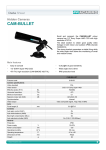
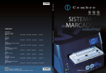
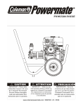
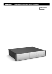
HOT / COLD WATER PRESSURE WASHER RANGER
Item 157394
P.O. Box 1499
Burnsville, MN 55337-0499
1-800-270-0810
NORTH STAR RANGER
Pressure Washer
HOT- COLD
Congratulations on your purchase of the RANGER 157394 Pressure Washer!
Your pressure washer is made of high quality components to ensure the top performance you
demand. Take the time to read this entire manual so you better understand the machine,
how to operate it, the maintenance required and the safety precautions. You will find the
assembly, operating, maintenance and troubleshooting instructions included. Be sure everyone
who operates and/or maintains the equipment has read and understands this manual, the engine
operations and the safety precautions. The time you take now will prolong the life of your
machine and prepare you for its safe operation. Enjoy the exceptional performance of your
Pressure Washer, the industry leader!
!
This symbol means CAUTION, WARNING OR DANGER!
Read and understand the instruction because it has to do with safety.
Failure to comply with the instruction may result in personal
injury or damage to the product.
If an injury ever occurs, seek medical attention immediately.
TABLE OF CONTENTS
SAFETY INSTRUCTIONS................................................................................................ 4
Unpacking ..................................................................................................................................... 5
ELECTRICAL REQUIREMENTS .................................................................................... 6
INSTALLATION INSTRUCTIONS .................................................................................. 7
PRE-OPERATION CHECK ............................................................................................... 7
OPERATING INSTRUCTIONS ........................................................................................ 8
Starting the Pressure Washer ......................................................................................................... 8
Cold Water Operation.................................................................................................................... 8
Hot Water Operation...................................................................................................................... 9
Stopping the Pressure Washer ..................................................................................................... 10
Using the Detergent Injector ....................................................................................................... 10
MAINTENANCE ............................................................................................................. 11
TROUBLESHOOTING.................................................................................................... 12
PARTS ASSEMBLY AND IDENTIFICATION ..........................................................13-19
-3-
SAFETY INSTRUCTIONS
!
Read and understand these instructions because they have to do with
safety. Pay particular attention to the safety symbol throughout this
manual. Failure to comply with these instructions may result in personal
injury or product damage.
ELECTRICAL SAFETY
1.
Properly ground this unit. Failure to ensure proper grounding can cause serious personal injury.
Never use a two-prong adapter on the three-prong electrical plug that is installed.
2.
Be certain all switches are “OFF” before plugging the unit into a compatible 120 volt power
source.
3.
Always turn off and unplug the unit from the power source if leaving unattended. Never leave
unit unattended while running.
4.
Never allow an electrical cord or connections to lay in water, it can cause a serious/fatal shock.
5.
Do not use this unit on or near any electrical installations, including electrical outlets, light bulbs,
fuse boxes or transformers. Severe electrical shock can occur.
6.
Unplug the unit from power source before attempting any repairs. Electrical repairs are best
suited to a licensed electrician.
7.
Follow all local, state and federal electrical installation codes.
VENTILATION AND FIRE SAFETY
8.
Use only No. 1 or No. 2 Diesel, to fill the fuel tank. Never use kerosene, gasoline, crankcase
drainings or oil containing gasoline/solvents, these can ruin your pressure washer.
9.
Fill the fuel tank slowly and only when the unit is COOL.
10. Never operate the unit near dust, gases, flammable vapors or other ignitable materials.
11. Always operate the pressure washer with the hood cover in place.
12. Allow the unit to cool down after stopping the pressure washer before leaving it unattended.
See cool down procedure in STOPPING THE PRESSURE WASHER section.
13. Consult a qualified heating contractor for permanent installation. Follow all local, state and
federal codes.
14. Always be sure there is adequate oxygen and ventilation during indoor use. Carbon monoxide
gas is odorless and colorless, it can cause serious illness end even death. Vent all burner exhaust
outside the building. Poorly ventilated areas cause bad combustion, motor overheating and
serious danger.
15. Never alter or modify the unit or its safety features. Be sure all components can handle the high
pressure this unit generates.
16. Be sure all connections are secure before operating the unit. Do not over tighten pressure washer
adjustments; excess pressure, irregular unloader operation and wear may occur.
-4-
GENERAL SAFETY
17. Always wear safety glasses or goggles when operating the unit.
18. Always point the wand away from people and animals. High pressure streams will penetrate the
skin. Seek medical attention immediately if fluid penetrates skin. Do not treat as a simple cut.
19. Always release system pressure after shutting off the pressure washer by squeezing the wand
trigger. Never leave the unit unattended with system still pressurized.
20. High pressure spray will shatter fragile materials. Never spray directly at glass or other breakable
objects.
21. Be firmly braced before squeezing the wand trigger “on”. High pressure stream may cause loss
of balance.
22. Never operate the pressure wand in high levels unless the proper safety equipment to prevent
fails is in place.
23. Inspect pressure hose daily for signs of wear. Never lay hose on the heat coil or drag over
abrasive surfaces.
Replace hose and other components promptly when leaks or wear is discovered. Never place
your hand over a pressurized leak.
24. Repair any leaks before operating the unit. Any fuel oil, pump oil or water leaks should be
serviced at your nearest Northern store or call customer service at 1-800-270-0810.
25. Use only Northern parts for replacements in your pressure washer. Other brand components may
cause hazardous operating conditions and will void warranty.
DETERGENT SAFETY
26. Do not alter the soap injecting system on the unit or use it in any manner not described in
this manual.
27. Always wear safety goggles when operating the unit and other safety attire recommended by
the detergent manufacturer. Protective clothing like rubber gloves, rubber suits and respirators
may by necessary.
28. Never use acid type cleaners or other highly corrosive detergents with this pressure washer.
29. Know your detergents! Follow all appropriate instructions for preparation, use, safety and
transportation of the detergent. Keep all detergents away from children. In an emergency, tell the
physician exactly what detergent you are using.
UNPACKING
Closely inspect all the contents of the RANGER 157394 carton.
Damaged components?
Contact the freight company that delivered the unit and file a claim.
Missing components?
Contact our Customer Service department at 1-800-270-0810.
-5-
ELECTRICAL REQUIREMENTS
“The supply and internal wiring of portable high pressure spray washing machines shall have ground-fault-circuitinterpreter (GFCI) which is designed to protect people from line-ground shock hazards”, National Electric Code
(NEC) 1987, 422, 8 (d) (3).
- All equipment and power cords connected down-line from the GFCI are protected.
- GFCI does not protect against line-to-line or line-to-neutral faults.
- GFCI does not protect against short circuits or overloads. Use a fuse or circuit breaker to guard against
these occurrences.
Northern recommends that all electrical service be performed by a licensed electrician.
- All electrical connections must be made according to local, state, and federal codes to maintain a valid
warranty.
- Connect the cord to a circuit that is wired for the 120 volts shown on the identification plate of the unit and
properly electrically ground the connection.
GROUNDING INSTRUCTIONS
This pressure washer must be grounded. Grounding provides a path of least resistance for electric current to reduce
the risk of shock if the unit should malfunction or breakdown. For your safety, plug the cord equipped with an
equipment-grounding conductor and a grounding plug into an appropriate outlet. The outlet should be properly
installed and grounded according to local electrical codes and ordinances.
GROUND-FAULT-CIRCUIT-INTERRUPTER
A GFCI is built into the plug of the pressure washer power supply cord. This GFCI provides additional protection
from electrical shock. Use only the identical replacement parts that include GFCI protection when replacing the
plug or power cord.
EXTENSION CORDS
Only use outdoor approved, 3-wire extension cords with 3-prong grounding-type plugs and 3-pole cord connectors
that accept the plug from the unit. Outdoor cords are identified by: “Acceptable for outdoor appliances; store
indoors while not in use”. Extension cord must have an electrical rating not less than the rating of the product.
Do not use a damaged extension cord or abuse the cord by yanking. Keep cord away from heat sources and
sharp objects. Always disconnect the extension cord from the power supply before disconnecting the unit from
the extension cord,
!
Improper connection of the equipment-grounding conductor can result
in a risk of electrocution. Check with a licensed electrician if you doubt
whether an outlet is properly grounded. Do not modify the product
plug, install a proper outlet with a licensed electrician. Reduce the risk
of electrocution, keep all connections dry and off the ground. Do not
touch with wet hands.
VENTILATION REQUIREMENTS
Permanent installation in an enclosed area or indoors should be performed by a qualified contractor. The burner
exhaust must be stacked to the outside atmosphere and a barometric draft regulator is required as well.
-6-
INSTALLATION INSTRUCTIONS
If installing the RANGER 157394 indoors or in an enclosed area, observe the following guidelines:
- Operate the unit on a level surface to ensure proper lubrification to the water pump.
- Be certain the ambient temperature of the environment does not exceed 100°F. This ensures adequate air
supply for the burner,
- Do not expose the unit to rain, snow or freezing temperatures.
- Do not install where dust, vapors or combustible materials will be present.
PRE-OPERATION CHECK
CLOTHING
Proper clothing is essential for your safety. Use whatever is necessary to protect your eyes, ears, feet and skin.
Additional safely accessories (like a respiratory mask) may be required when using detergents with this washer.
PUMP
Check pump oil level at least once a week. Open the cover hood on the unit, remove oil plug. Oil level should be
2 mm from elbow surface. If oil is needed, fill with SAE 80-90, non-detergent oil. Do not overfill.
WATER SUPPLY
3/4"
1.
3/4"
Connect the water supply to the 314” female garden hose swivel on the water inlet port of the unit.
Connect the other end of the hose to the pressurized water supply. The supply hose should have a
314” inside diameter (ID) and be no longer than 50 feet.
2.
The water supply pressure must be a minimum of 20 pounds per square inch (PSI) and a
maximum of 125 PSI. The flow rate must be at least 3 gallons per minute (GPM).
3.
Use a water softener if there is high mineral content in the water of your area. High mineral
content causes excessive scale build-up in the coil/heat exchanger.
4.
Connect one end of the high pressure discharge hose to outlet port on the pressure washer and
the other end to the wand/gun assembly.
!
Be sure all connections are securely tightened.
Sudden release of high pressure streams can cause serious injury.
-7-
OPERATING INSTRUCTIONS
STARTING THE PRESSURE WASHER
BEFORE STARTING THE PRESSURE WASHER
1.
Read all safety instructions throughout this manual.
2.
Be sure the motor switch is in the “OFF” position, red button pushed.
3.
Ensure outlet is the proper voltage (120 volts).
4.
Insert the male power plug into a grounded AC outlet.
5.
Press and release the “RESET” button on the GFCI power cord.
6.
Press “RESET” each time after plugging the GFCI power cord into a power source.
20 amp outlet
COLD WATER OPERATION
1.
After following all preparation instructions, turn the water supply on.
2.
Turn the unit on by pushing the pump switch on the control panel. Once the unit starts, squeeze
the trigger gun “ON” for 2 minutes to purge all air and mineral deposits from the system. This
operation is to be done without lance terminal end.
3.
Turn the pump switch to OFF position, release the trigger gun and lock in the “OFF” position.
Fit the lance terminal end. To ensure you are in the high pressure mode, turn the nozzle holder
to the right.
4.
Your RANGER 157394 is now ready to be used as a cold water pressure washer. Turn the
unit on by pushing the pump switch on the control panel. Squeeze the trigger-gun to spray a high
pressure stream and release the trigger to stop the stream.
5.
Adjust pressure with the unloader valve to the desired pressure.
!
Do not allow the unit to operate in bypass mode (with trigger
released in the “OFF” position) for more than 3 minutes.
Premature failure of pump packing may occur if left in bypass
mode for longer than 3 minutes.
Never look directly into the nozzle unless it is disconnected from the
spray wand.
-8-
HOT WATER OPERATION
1.
Fill fuel tank with 1.8 gallons of #l or #2 Diesel.
2.
Be sure trigger gun is locked in the “OFF” position and remove the nozzle/wand assembly.
3.
Turn the unit on by pushing the pump switch on the control panel. Once the unit starts, squeeze
the trigger gun “ON” for 2 minutes to purge all air and mineral deposits from the system.
4.
Turn the pump switch to “OFF” position, release the trigger gun and lock in the “OFF” position.
Connect the nozzle-wand assembly to the gun assembly. To ensure you are in the high pressure
mode, turn the nozzle to the right.
5.
Turn the pump switch to “ON” position, turn the burner knob located on the control panel to “ON”
(position 1) Squeeze the trigger gun to spray, burner only fires when the trigger is squeezed.
6.
Do not allow the unit to operate in the bypass mode (trigger not squeezed) for more than 3
minutes. Failure of pump packing may result
7.
The unit is now ready to be used as a hot water pressure washer. Squeeze the trigger-gun to spray
a high pressure stream, and release the trigger to stop the stream.
8.
Cool down the heat exchanger by turning the burner knob “OFF” (0 position). Allow unit to run
with trigger in the squeezed, “ON” position for at least 3 minutes.
NOTE:
On initial startup, water will begin turning hot in 30 seconds, reaching maximum temperature in 3 minutes with
trigger squeezed. Burner stops firing when the trigger is released or when water exceeds the temperature setting.
!
CAUTION!
EXPOSED METAL EXHAUST OUTLET AND HOSE
CONNECTIONS DURING HOT OPERATION ARE EXTREMELY
HOT!
-9-
STOPPING THE PRESSURE WASHER
!
To protect your safety and the service of your RANGER 157394, you
must follow the procedure for stopping the pressure washer outlined
below:
1.
Run one gallon of clean water through the used detergent lines. (If detergent has been used during
this operation run).
2.
Turn burner switch to “OFF” (0 position).
3.
Squeeze the trigger and discharge cool water for 3 minutes to cool the burner component.
4.
Turn the unit “OFF” with the main switch on the control panel.
5.
Turn off the water supply immediately.
6.
Squeeze the trigger gun to relieve system pressure and drain excess water.
7.
Disconnect power cord and unit hoses.
USING THE DETERGENT INJECTOR
This feature is designed for use with mild detergents. North Star detergents are highly recommended for use with
all North Star pressure washers.
1.
Prepare cleaning solution according to the detergent label directions.
2.
Immerse the strainer end of the clear vinyl hose into the detergent solution to allow detergent to
siphon. Turn the nozzle at the end of the wand to the left for low pressure.
3.
Start the unit as directed in the OPERATING INSTRUCTIONS. Brace yourself and the triggered
gun. The detergent and water mixture will exit the low pressure nozzle.
4.
Apply the solution by spraying from low surface and move up; use long, overlapping strokes.
Applying from the bottom, up helps avoid streaking. Do not allow the detergent solution to
dry on any surface.
5.
Turn nozzle at the end of the wand to the right for the high pressure rinse mode. It takes 30
seconds to purge all detergent from the system lines.
6.
Start at the top and work down for the best rinsing results.
7.
Rinse the detergent injector system by running 1 gallon of clean water through after each use.
This prevents corrosion or detergent residue that causes mechanical problems during later uses
of your RANGER 157394.
- 10 -
MAINTENANCE
1.
Inspect and clean the water intake screen on the unit before each use.
2.
Always be sure the unit is receiving the proper 120 volts. Be certain the cord is equipped with
the appropriate ground prong plug to ensure proper grounding. Electrical cords and connections
should not contact water.
3.
Always follow STOPPING THE PRESSURE WASHER instruction outlined on page 10 of this
manual.
4.
Do not operate the unit in bypass mode (trigger not squeezed) for more than 10 minutes, this will
cause premature failure of the pump packings.
5.
Only run pump with water supply turned on all the way. Never allow pump to run dry.
6.
Run a gallon of clean water through the injection line after each use. This flushes out any
corrosive chemicals and prevents residue from damaging moving parts.
7.
Use a water softener if the water supply has a high mineral content. This will avoid accumulation
of mineral deposits in the coil/heat exchanger. If a softener is not available it is necessary to
“de-scale” the coil occasionally. See your nearest Northern store or call 1-800-270-0810 for
customer service.
8.
Detergents are corrosive. It may be necessary to repair or replace components on the detergent
injector system periodically as part of standard maintenance.
9.
Never pump acids, alkalines or abrasive fluids through the unit.
10. Never operate the unit without the hood cover.
11. Eliminate leaks found in the pumping system by removing suspect parts, applying sealant to the
threads and reinstalling. If using Teflon tape, be sure no tape gets into any plumbing, this causes a
plugged spray nozzle and internal problems.
12. Change pump crankcase oil after first 50 hours of use, then every 250 hours. Use only
SAE 80-90, non-detergent oil. Oil level should be 2 mm. from transparent elbow surface. Check
oil once a week.
13. Change fuel filter to burner every 6 months and screen in the fuel pump on the burner each year.
Be sure to use only high quality No. 1 or No. 2 Diesel.
14. Never spray water directly into the unit or store outdoors where it can be exposed to rain or other
adverse weather conditions.
15. Never store the unit in a freezing environment. This causes the coil/heat exchanger to rupture
and the water pump to “lock up”.. Never pour hot water on a frozen pump, a temperature change
greater than 1 50, F can crack the water pump. Again, do not store the unit in a freezing
environment.
- 11 -
TROUBLESHOOTING
SYMPTOMS
CAUSES
REMEDIES
The water pump will not start
The motor thermic protection is open
Check the mains voltage (+/- 5%
tolerance). Check the phases
in the plug are connected well.
The water pump will not enter
in bypass
The no-return valve does not seal
Replace the valve or the gasket
and check the pressure valve
body wear.
Leakage from the water system
of the gun
Eliminate the leaks
Nozzle worn
Replace the nozzle
Pressure ball or adjustment housing
worn or spring broken
Replace the faulty part
Pressure valve gaskets worn
Replace the valve gaskets
Pistons seal gasket worn
Replace the gaskets
Nozzle holding head in position
low pressure
Turn the head on high pressure
Water supply insufficient
Check the water supply flow and
the relative pressure (2÷10)
The water pump does not reach
maximum pressure
Strong vibrations on the water pump
Check the water filter and clean
it if necessary
Prime the pump without the lance
Alien matter under a check valve
Check the valves, clean and reassemble
Diesel filter blocked
Clean the filter
Diesel nozzle blocked
Clean the filter
Worn or broken electrodes
Replace the electrodes
The pressure switch remains open
Replace the pressure switch
Safety thermostat is open
Replace the safety thermostat
Anormal noise of Diesel pump
Low diesel
Fill diesel tank or work on cold water
No detergent suction
High viscosity of the employed
detergent
Further dilute the detergent
Detergent filter blocked
Clean the filter
The burner will not start
- 12 -
FRAME, COWLING ASSEMBLY EXPLODED VIEW
N°
1
2
3
4
5
6
7
8
9
10
11
12
13
14
15
16
17
18
19
20
21
22
23
24
25
26
27
28
29
30
31
Code
0477 0096
2416 0104
3208 0800
2803 0322
2803 0258
3200 0017
3002 0322
3607 0106
2811 0083
0011 0001
2422 0012
2422 0020
2000 0051
1002 0079
2803 0408
3208 0895
1003 0067
3029 0011
3200 0039
3609 0030
2437 0001
2819 0009
2815 0026
2434 0022
3206 0272
2434 0012
2811 0023
0604 0095
3208 0823
1002 0110
3208 0824
Description
Cover
Roll-bar
Copper Hose
Coupling
“T” Coupling
Plug
Diesel Pump Support
Hexagonal Screw
Washer
Adapter
Diesel Pump
Diesel Pump Kit
Nipple
Diesel Filter
Coupling
Diesel Hose
Hose Clamp
Diesel Tank
Diesel Tank Plug
Screw
Front Bumper
Spring Washer
Rivet
Cable Holder
Frame
Cap
Washer
Nut
Suction Hose
Water Filter
Suction Hose
Note
Ø4
Ø4 GC1/8”
G1/8
G1/8x8
M6x10
13,5x19x1,5
1/4 M-F
1/4 M-M
G1/4 PG Ø7
M5x20
M5x13
Ø6,6x18x2
M6
L = 210
Qty
1
2
1
1
1
1
1
2
1
1
1
1
1
1
1
1
1
1
1
8
1
8
8
1
1
1
1
1
1
1
1
Model
N°
32
33
34
35
36
37
38
39
42
43
44
45
46
47
48
49
50
51
52
53
54
55
56
57
58
59
60
61
62
63
64
- 13 -
Code
2811 0074
3625 0037
2437 0002
0600 0039
1201 0078
0604 0066
2800 0074
3200 0062
2000 0089
1227 0002
1227 0015
0011 0003
1209 0099
1209 0097
1215 0148
0604 0095
0466 0014
1209 0007
3230 0011
2803 0503
3230 0003
1209 0099
2417 0054
2803 0260
2810 0030
0009 0179
0402 0189
2810 0031
5018 0038
1803 0030
1817 0032
Description
Note
Washer
Special Screw
Rear Bumper
Special Bolt
Gasket
Nut
Straight Hose Tail
Plug
Nipple
Ring Nut for Cable Holder
Ring Nut
Adapter
Copper Washer
Copper Washer
Safety Valve
Nut
Throttle Conveyor
Copper Washer
Regulation Thermostat
Coupling
Safety Thermostat
Copper Washer
Reduction
Delivery Coupling
Wheel
Ring
Wheel Cover
Wheel Kit
Handle Fitting Assembly
Handle Bar
Handle Bar Knob
Ø4,36x16
3/4M-3/8M
PG16
M/F G3/8
M6
Ø20
Qty
2
2
1
5
2
1
1
4
1
1
2
1
1
1
1
1
1
1
1
1
1
1
1
1
4
4
4
4
1
1
2
Model
PUMP, MOTOR ASSEMBLY EXPLODED VIEW
Pump & Motor CO90270079
Cost more than whole unit
N°
1
2
3
4
5
6
7
8
9
10
11
12
13
14
15
16
17
18
19
20
21
22
23
Code
1211 0021
3208 0726
3208 0728
2803 0244
1210 0227
3003 0011
1802 0155
0801 0038
0801 0040
2417 0032
1816 0101
1215 0118
2803 0218
1209 0091
2825 0018
1209 0097
2421 0004
3202 0155
1210 0048
1205 0025
1802 0125
3604 0017
3009 0087
Description
By-Pass Elbow Coupling
By-Pass Hose
H.P. Hose
Detergent Coupling
O-Ring
Detergent Ball
Detergent Spring
Detergent Injector
Detergent Injector Kit
Reduction
Gauge
Unloader Valve
“T” Coupling
Copper Washer
M/F Reduction
Copper Washer
Pressure Switch
Plug
O-Ring
Suct./Del. Valve Cage
Spring
Suct./Del. Valve
Suct./Del. Valve Seat
Note
3/8”
G3/8-G1/4
2,62x20,24
Qty
1
1
1
1
1
1
1
1
1
1
1
1
1
1
1
1
1
6
6
6
6
6
6
Model
N°
24
25
26
27
28
29
30
31
32
33
34
35
36
37
38
39
40
41
42
43
44
45
46
- 14 -
Code
1210 0046
1220 0029
3202 0093
3218 0101
1241 0031
0009 0169
1210 0333
1210 0337
0019 0081
3200 0055
2432 0013
3609 0005
3208 0823
1210 0225
1802 0153
2409 0057
0009 0173
0009 0175
0436 0011
0001 0374
0438 0046
0019 0036
1009 0092
Description
Note
O-Ring
Suct./Del. Valve Ass.y kit
Plug
Pump Manifold
Packing
Packing Retainer
O-Ring
O-Ring
Oil Seal
Plug
Piston Holder
Screw
Suction Hose
O-Ring
Piston Spring
Piston Guides
Ring
Ring
Complete Axial Bearing
Eccentric Shaft
Ball Bearing
Oil Seal
Front Motor Flange
2,62x17,13
1,78x23,52
2,62x15,08
M8x20
Ø2,62x88,57
Qty
6
6
1
1
3
3
3
3
3
3
1
2
1
1
3
3
3
3
1
1
1
1
1
Model
PUMP, MOTOR ASSEMBLY EXPLODED VIEW
N°
47
48
49
50
51
52
53
54
55
56
57
58
59
60
61
62
63
64
65
66
67
Code
1201 0124
0001 0464
3041 0152
1201 0124
0438 0059
1009 0094
3609 0129
3622 0028
3632 0028
3607 0177
2811 0023
0466 0012
3607 0097
2811 0030
1201 0094
1602 0051
0604 0046
3208 0831
2811 0030
3607 0177
2803 0312
Description
Note
Motor Gasket
Rotor Shaft
Stator
Motor Gasket
Ball Bearing
Back Motor Housing
Screw
Stop Adjustable Nut
Fan Kit
Hexagonal Screw
Washer
Shraud Cover
Hexagonal Screw
Washer
Gasket
Key
Nut
H.P. Hose
Washer
Hexagonal Screw
Oil Level Wiever
M5x20
M8x10
M6x14
Ø6,6x18x2
M6x16
Ø6,4x12,5x1,6
5x5x20
M5x6
Ø6,4x12,5x1,6
M6x14
Suction / Delivery Valve Kit
Kit A
Model
1
1
1
1
1
1
4
1
1
2
2
1
4
4
2
1
4
1
2
2
1
N°
68
69
70
71
72
73
74
75
76
77
78
79
80
81
82
83
84
85
86
87
88
(5025 0007)
5025 0007
N°
19
20
21
22
23
24
Cod.
Qty
1210 0048
1205 0025
1802 0125
3604 0017
3009 0087
1210 0046
6
6
6
6
6
6
Seal Kit
Kit B
Qty
(5019 0025)
5019 0025
N°
28
30
31
Cod.
Qty
1241 0031
1210 0333
1210 0337
3
3
3
- 15 -
Code
3200 0031
1210 0383
1210 0055
1210 0091
2803 0314
0601 0197
1220 0029
3609 0127
3200 0017
3607 0177
0604 0010
2811 0023
3002 0326
3002 0328
0604 0075
2811 0006
3226 0075
2811 0030
3607 0106
3609 0113
0535 0065
Description
Plug
O-Ring
O-Ring
O-Ring
O-Ring
Valve Shim
Suct./Del. Valve Ass.y kit
Screw
Plug
Hexagonal Screw
Nut
Washer
Spacer
Support
Nut
Washer
H.T. Transformer
Washer
Hexagonal Screw
Screw
H.T. Cable Kit
Note
Ø1,78x3,69
Ø1,78x6,07
M8x140
G1/8
M6x14
M6
Ø6,6x18x2
M4
Ø4,3x9
Ø6,4x12,5x1,6
M6x10
M5x10
Qty
1
2
1
1
1
1
6
4
1
1
1
1
1
1
2
2
1
1
1
2
1
Model
UNLOADER VALVE EXPLODED VIEW
N°
1
2
3
4
5
6
7
8
9
10
11
12
13
14
Code
1817 0031
2803 0262
1802 0119
3002 0334
0015 0118
0009 0096
1210 0039
1227 0022
3622 0030
3202 0094
1210 0040
1210 0055
0009 0167
1209 0082
Description
Knob
Coupling
Unloader Spring
Spacer
Rod
Ring
O-Ring
Ring Nut
Stop Adjustable Nut
Cap
O-Ring
O-Ring
Ring
Copper Washer
Note
Ø1,78x 7,66
M4x4
Ø1,78x15,6
Ø1,78x6,07
Qty
1
1
1
1
1
1
1
1
1
1
1
1
1
1
Model
N°
15
16
17
18
19
20
21
22
23
24
25
26
27
28
- 16 -
Code
0424 0206
1809 0016
3036 0004
1210 0186
1210 0040
2803 0266
2803 0264
1209 0082
1210 0198
3600 0060
1802 0120
1210 0040
2803 0268
3600 0062
Description
Unloader Body
Half-Ball
Seat
O-Ring
O-Ring
By-Pass Coupling
Special Screw
Copper Washer
O-Ring
Check Valve
Check Valve Spring
O-Ring
Coupling
Check Valve Kit
Note
Ø1x10
Ø1,78x15,6
Ø2,5x4
Ø1,78x15,6
Qty
1
1
1
1
1
1
1
1
1
1
1
1
1
1
Model
ELECTRIC SYSTEM EXPLODED VIEW
N°
1
2
3
4
5
6
7
8
9
10
11
12
13
14
Code
3625 0003
0460 0030
2416 0095
1410 0066
0456 0100
1817 0039
3625 0035
0457 0027
0402 0198
1210 0396
0204 0041
3230 0011
3001 0084
1814 0004
Description
Note
Qty
Special Screw
Switch Cover
Switch Protection
Switch
Electrical
Burner Knob
Screw
Electrical Panel Sticker
Electrical Panel Cover
O-Ring
Thermostat Bushing
Regulation Thermostat
Electrical Box
Cable Connector
M6x6
2
1
1
1
3
1
6
1
1
1
1
1
1
1
Ø3,5x19
Ø2,62x190,17
Model
N°
15
16
17
18
19
20
21
22
23
24
25
26
27
Code
0434 0023
2434 0039
1201 0102
3625 0019
2819 0007
0456 0116
2434 0034
1227 0027
3625 0019
2434 0033
0434 0021
1229 0025
1209 0007
Description
Note
Qty
Capacitor
Cable Holder
Switch Box Seal
Screw
Spring Washer
Electrical Cable
Cable Holder
Ring Nut
Screw
Cable Holder
Capacitor
Sheat
Copper Washer
85µf
1
1
1
1
1
1
1
1
4
1
1
1
1
M4x12
L = 6000 mm
M4x12
Ø18
50µf
3rd Capacitor (start) CO04340028 not shown
- 17 -
Model
BURNER, BOILER EXPLODED VIEW
N°
1
2
3
4
5
6
7
8
9
10
11
12
13
Code
3208 0800
2803 0320
3625 0013
3200 0074
3019 0035
0602 0047
0602 0048
3608 0004
3400 0340
0805 0017
2819 0020
3625 0046
0335 0026
Description
Copper Diesel Hose
Helbow Coupling
Screw
Plug
Outer Seeger
Electrode Holder Disc
Air Turbolence Ring
Screw
Diesel Nozzle
Bifilar Electrode
Spring Washer
Screw
Burner Head Kit
Note
90°
4,2x9,5
Ø22
M3x6
0,90 - 60°W CT
D.15x5,2x0,4
M5x12
Qty
1
1
3
1
1
1
1
3
1
1
1
1
1
Model
N°
14
15
16
17
18
19
20
21
22
23
24
25
26
- 18 -
Code
1202 0052
0535 0065
0604 0010
2811 0030
0402 0132
0402 0134
0424 0204
0424 0200
3044 0008
2822 0008
2822 0010
3607 0010
2811 0016
Description
Hook
H.T. Cable Kit
Nut
Washer
Boiler Cover
Exaust Cover
Internal Boiler Body
External Boiler Body
Coil
Hard Refractory Pad
Soft Refractory Pad
Hexagonal Screw
Washer
Note
M6
Ø6,4x12,5x1,6
M8x16
Ø8,4x17x1,6
Qty
2
1
3
3
1
1
1
1
1
1
1
5
5
Model
GUN, HOSE, WAND ASSEMBLY EXPLODED VIEW
24100112
33010787
34000402
33010639
N°
1
2
3
4
5
6
7
8
9
10
11
Code
2410 0060
3301 0635
3400 0254
3301 0554
1407 0027
3208 0743
3301 0487
1002 0055
3208 0705
2803 0267
1210 0227
Description
Note
Spray gun
Lance Kit
Water Nozzle
H.P. Hose Kit
Quick Coupling
H.P. Hose
Detergent Hose Kit
Detergent Filter
Detergent Hose
Detergent Coupling
O-Ring
15 035 Ø1,14 1/4
5/16” L = 10 m
M22X1,5
5/16” L = 10 m
L = 750 mm
Ø1,78x5,28
- 19 -
Qty
1
1
1
1
1
1
1
1
1
1
1
Model