1
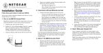
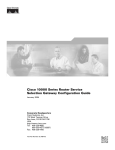
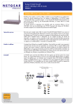
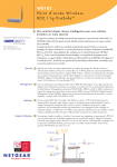
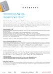
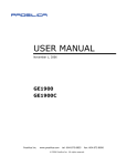
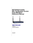
500mW Bi-directional Booster
ANT24BNA
Power Injector
ANT24BDC
Installation Guide
Introduction
This section introduces the NETGEAR ANT24BNA 500 mW Bi-directional Booster and the
NETGEAR ANT24BDC 6 VDC, 1.5A Power Injector and related components.
The 500-milliwatt bi-directional power booster for the NETGEAR ME103 802.11b ProSafe
Wireless Access Point increases the transmission signal from an average 50 mW to 500 mW
and amplifies the signal by 10 dB (10 times) in receive mode. Use this when you want to
maintain a single access point device to cover a larger area.
The ANT24BDC enables locating an antenna and a NETGEAR ANT24BNA booster more
than 30 feet away from the wireless unit in a remote area where electrical power is not available.
DC power is supplied to the booster through the antenna cable by means of the power injector.
This eliminates the need to install extra wires. Moreover, unlike power over Ethernet devices,
this configuration never needs to be reset.
The booster and power injector are part of a wireless system, including the access point, cables
and antennas. According to FCC regulations, the booster can only be used with the wireless
access point that is provided with it. Check http://www.NETGEAR.com/go/antennas_fcc for a
list of approved devices.
Power adapter
Installation Guide,
Warranty card and
Support information card
Wall and ceiling
mount bracket
and hardware
500 mW Bi-directional booster
ANT24BNA
500 mW Booster Package Contents
The package should contain
•
NETGEAR 500mW Bi-directional Booster for 802.11b ANT24BNA
•
NETGEAR PWR-10015-01 DC power adapter
•
Ceiling/wall mount bracket and hardware
•
Installation guide
•
Warranty card
•
Support information card
1
Power Injector Package Contents
Installation Guide,
Warranty card and
Support information card
Power Injector ANT24BDC
The package should contain
•
NETGEAR 6 VDC 1.5A Power Injector ANT24BDC for bi-directional booster ANT24BNA
•
Installation Guide
•
Warranty card
•
Support information card
If any of the parts are incorrect, missing, or damaged, contact your NETGEAR dealer. Keep the
carton, including the original packing materials, in case you need to return the product for repair.
NOTE: To obtain optimal results in extending wireless range with antenna installations, it is
recommended that a qualified professional installer service is consulted for site survey and
proper installation.
–
Use a NETGEAR antenna cable of no more than 3 m between the Power Injector and
the access point.
–
For optimal performance, the combined length of both NETGEAR antenna
cables should not exceed 13 m. If the length exceeds 13 m, the overall performance
will decrease.
Antenna cables have intrinsic loss at 2.4 GHz which can decrease range performance. The
longer the cable, the higher its loss. To achieve optimal performance, use the shortest antenna
cable you can from the antenna to the ANT24BNA booster. Cable loss between the booster
ANT24BNA and antenna in the transmit and receive functions cannot be compensated.
However, the NETGEAR antenna cable between the ANT24BNA booster and the wireless
access point can be as long as 10 m without performance reduction. By the same token, a 3 m
NETGEAR antenna cable between the optional injector and wireless access point can be added
without performance reduction.
In receive mode, the booster amplifies the signal by 10 dB with a low noise amplifier. This
amplification can compensate for cable loss up to 10 dB (booster to wireless node only). In
transmit mode, the booster accepts the 802.11b input signal as low as 5 dBm and amplifies it to 27
dBm (variable power amplifier). The typical output power of an 802.11b wireless node is 15dBm
or more. So, there is a 10 dB margin to fully compensate for cable loss. The loss in the cable
between the booster and the wireless node only can be completely compensated in transmit and
receive mode up to 10 dB loss without any reduction of performance.
Placement and Other Important Considerations
Installing the Booster
Observe the following guidelines when configuring your Booster for 802.11b. In order to comply
with FCC regulations you must use NETGEAR antenna cables (ACC-10314-01, 02, 03 or 04)
with these products. These antenna cables are low loss and are ideally suited for the NETGEAR
booster, power injector and antennas. Performance (range) can be drastically reduced if longer or
higher loss antenna cables are used.
Turn off your ME103 Wireless Access Point and connect your wireless accessories according to
the illustration. After attaching your new antenna, reconnect your wireless device to the network
and turn it on.
•
Place the ANT24BNA booster as close as possible to the antenna with a short NETGEAR
antenna cable. The shortest FCC approved antenna cable is the NETGEAR 1.5 m (ACC10314-01) cable.
•
Place the longer NETGEAR cable (up to 10 meters) between the ANT24BNA booster and
the access point. The overall performance will decrease if the length exceeds 10m.
•
If you use a ANT24BDC Power Injector to power the booster remotely, follow these
guidelines:
–
2
Use the longer NETGEAR antenna cable (up to 10 m) between the booster and the
power injector.
3
One Antenna Port, One Booster and One Antenna
Two Antenna Ports, Two Boosters and Two Antennas
DC Block
DC Block
Antenna
e. g. NETGEAR
ANT24O5
Antenna
e. g. NETGEAR
ANT24O5
Wireless unit
Wireless unit
Connect
DC
cable
Connect
Antenna
cable
500 mW Booster ANT24BNA
NETGEAR
Antenna
cable (short)
ETHERNET
ETHERNET
Connect
Antenna
cable
Connect
Antenna
cable
5-12V DC
Connect
Antenna
cable
NETGEAR
Antenna
cable (short)
NETGEAR Antenna cable
(short, medium or long)
500 mW Booster ANT24BNA
Connect
Antenna
cable
Current antenna
Do NOT remove
Antenna
e. g. NETGEAR
ANT24O5
4
ETHERNET
Connect
DC
cable
5-12V DC
RESET
Primary
Secondary
500 mW Booster ANT24BNA
NETGEAR
Antenna
cable (short)
500 mW Booster ANT24BNA
NETGEAR
Antenna
cable (short)
Connect
Antenna
cable
NETGEAR Antenna cable
(short, medium or long)
NETGEAR Antenna cable
(short, medium or long)
Connect
Antenna
cable
Wireless unit
Connect
Antenna
cable
Secondary
DC Block
DC Block
Connect
Antenna
cable
Primary
Antenna
e. g. NETGEAR
ANT24O5
Two Antenna Ports, One Booster and Two Antennas
Connect
DC
cable
5-12V DC
RESET
Connect
Antenna
cable
Connect
DC
cable
RESET
Connect
Antenna
cable
Connect
Antenna
cable
NETGEAR Antenna cable
(short, medium or long)
5
Installing the Booster with the
Optional Power Injector
Specifications
Note: As noted in the illustration below, be sure to disconnect the DC power adapter from the
ANT24BNA Booster for 802.11b, and connect it to the NETGEAR ANT24BDC Power Injector.
Current antenna
Do NOT remove
Connect
Antenna
cable
NETGEAR
Antenna cable
(short or medium)
Antenna
e. g. NETGEAR
ANT24O5
Injector NETGEAR
ANT24BDC
Wireless unit
ETHERNET
Primary
Connect
Antenna
cable
Connect
DC cable
6
Operating Mode
TDD Burst Mode
DC Surge Protection
600 Watts TVS @ 6VDC
Current Drain (TDD Mode)
700 mA type. @ 6VDC
Transmit Power
26.5 dBm minimum
Transmit Input Power
+ 5 dBm minimum
Transmit Ramp Up Time
3 µs maximum
Receiver Gain
10 dB typical
Receiver Frequency Response
±1 dB over operating range
Receiver Noise Figure
5 dB maximum
Receiver Ramp Down Time
3 µs maximum
Material
ABS
Color
White
Device Size (l x w x h)
130 x 75 x 37 mm (5.1 x 3.0 x 1.5 in)
Weight
5.0 g/1.1 lbs (including DC adapter)
RF Connector Type
SMA female reverse (2x), 1 for connection to antenna,
1 for connection to ME103 wireless access point
RF Connector Impedance
50 ± 5 Ohms
RF Connector Dielectric
Withstanding Voltage
750 VRMS maximum
RF Connector Insertion Loss
0.2 dB
DC Block NETGEAR
Connect
Antenna
cable
Connect
Antenna
cable
2400 to 2500 MHz
5-12V DC
Secondary
Connect
Antenna
cable
500 mW Booster ANT24BNA
Frequency Range
RESET
Do NOT connect
DC cable
NETGEAR
Antenna
cable (short)
Description
NETGEAR 500mW Bi-directional
Booster for 802.11b, with Two
Female Reverse SMA Connectors
NETGEAR Antenna
cable (medium or long)
7
Description
NETGEAR 500mW Bi-directional
Booster for 802.11b, with Two
Female Reverse SMA Connectors
RF Connector Recommended
Coupling Nut Torque
0.45 to 0.99 Nm (4.0 to 8.8 in.lb.)
RF Connector Coupling Nut
Retention Force
22.7 kg (50 lb) min.
RF Connector Contact
Captivation Axial
2.27 kg (5 lb) min.
RF Connector Body
Brass per JIS H3250 C3604 BD, Gold Plated per
MIL-G-45204
RF Connector Contact
Beryllium Copper per QQ-C-530, Gold Plated per
MIL-G-45204
Operating Temperature
Description
NETGEAR PWR-10015-01 DC
Adapter Specifications
AC Input Voltage
90 to 264 VAC
AC Input Frequency
50 to 60 Hz
AC Input Current
0.4 Arms for 115 VAC
0.2 Arms for 230 VAC
AC Inrush Current
30 A-Peak for 115 VAC
50 A-Peak for 230 VAC
Full Load, 25° C, Cold Start
Output Voltage
+6 V
Total Regulation
±5%
0 to 70° C (32 to 158° F)
Min/Max Load Current
0 A / 2.5 A
Storage Temperature
-30 to 80° C (-22 to 176° F)
Ripple And Noise
60 mVPP
Humidity
10% to 90%
Total Output Power
15 W
Warranty
1 year
Efficiency
65% minimum @115 VAC, 60 Hz, Full Load
Rise Time
100 ms maximum
Material
PVC + STEEL
Operating Temperature
0 to 40° C (32 to 104° F)
Storage Temperature
-40 to 70° C (-40 to 158° F)
Humidity
10% to 90%
Designed To Meet Standards
UL, CSA, TUV
Leakage Current
0.25 mA maximum
Over Current Protection
Short Circuit Protection
8
9
Specifications
ANT24BDC Power Injector for the
ANT24BNA Booster with Two
Female Reverse SMA Connectors
Description
ANT24BDC Power Injector for the
ANT24BNA Booster with Two
Female Reverse SMA Connectors
Operation Temperature
0 to 70° C (32 to 158° F)
Frequency Range
2400 to 2500 MHz
Storage Temperature
-10 to 80° C (14 to 176° F)
PTC Fuse
2.5 A / 30 V
Humidity
10% to 90%
Insertion Loss
1.5 dB maximum @ 2.4 to 2.5 GHz
Device Size (l x w x h)
88.2 x 58.9 x 33.4 mm (3.48 x 2.32 x 1.32 in)
Short Circuit Protection
PTC Fuse 2.5 A / 30 V
Weight
220 g (7.76 oz)
DC Supply Voltage
DC, 5 V to 12 V
Warranty
1 year
RF Connector Type
SMA female reverse (2x), 1 for connection to antenna, 1
for connection to ME103
RF Connector Impedance
50 ± 5 Ohms
RF Connector Dielectric
Withstanding Voltage
750 VRMS maximum
RF Connector Insertion Loss
0.2 dB
RF Connector Recommended
coupling nut Torque
.45 to .99 Nm (4.0 to 8.8 in.lb.)
RF Connector Coupling nut
retention force
22.68 kg (50 lbs.) minimum
RF Connector Contact
captivation axial
2.27 kg (5 lbs.) minimum
RF Connector Body
Brass per JIS H3250 C3604 BD, Gold Plated
per MIL-G-45204
RF Connector Contact
Beryllium Copper per QQ-C-530, Gold Plated per
MIL-G-45204
Material
Aluminum Alloy
Color
White
Description
10
11
Statement of Conditions
In the internal function, and/or reliability, NETGEAR reserves the right to make changes to the products described in
this document without notice. NETGEAR does not assume any liability that may occur due to the use or application
of the product(s) or circuit layout(s) described herein.
Federal Communications Commission (FCC) Compliance Notice:
Radio Frequency Notice
This device complies with part 15 of the FCC Rules. Operation is subject to the following two conditions:
1. This device may not cause harmful interference.
2. This device must accept any interference received, including interference that may cause undesired operation.
Note: This equipment has been tested and found to comply with the limits for a Class B digital device, pursuant to
part 15 of the FCC Rules. These limits are designed to provide reasonable protection against harmful interference in a
residential installation. This equipment generates, uses, and can radiate radio frequency energy and, if not installed and
used in accordance with the instructions, may cause harmful interference to radio communications. However, there is
no guarantee that interference will not occur in a particular installation. If this equipment does cause harmful
interference to radio or television reception, which can be determined by turning the equipment off and on, the user is
encouraged to try to correct the interference by one or more of the following measures: (1) Reorient or relocate the
receiving antenna, (2) Increase the separation between the equipment and receiver, (3) Connect the equipment into an
outlet on a circuit different from that to which the receiver is connected, (4) Consult the dealer or an experienced
radio/TV technician for help.
Federal Communications Commission (FCC) Radiation Exposure Statement
To ensure compliance with the FCC's RF Exposure requirements for saftey, all omni-directional antennas (Netgear
ANT24O5) must be installed to provide a separation distance of at least 20 cm from a person.
The panel antennas (Netgear ANT24D18) must be fixed mounted on a permanent structure to ensure a separation
distance of at least 50 cm from all people. The panel antennas can only be used for point-to-point applications and
may not be used for point-to-multipoint applications.
The antennas shall not be co-located with other transmitting devices.
Note: To meet FCC regulations, the system must be installed as shown in the diagrams. Substitution of cables and
access point provided and/or any modification to any of the components of this system will void the user's right to
operate it.
Check http://www.NETGEAR.com/go/antennas_fcc for a list of FCC approved antennas.
Use of this booster with any other devices is strictly prohibited by the FCC.
12
Technical Support
PLEASE REFER TO THE SUPPORT INFORMATION CARD THAT SHIPPED WITH
YOUR PRODUCT.
By registering your product at www.NETGEAR.com/register, we can provide you with faster
expert technical support and timely notices of product and software upgrades.
NETGEAR, INC.
Support Information
Phone: 1-888-NETGEAR (For US & Canada only) - 24x7 phone support
See Support Information card for other countries.
E-mail: [email protected] (24x7 online support)
www.NETGEAR.com
©2003 NETGEAR, Inc. NETGEAR, the Netgear logo, The Gear Guy, Auto Uplink and
Everybody's Connecting are trademarks or registered trademarks of Netgear, Inc. in the United
States and/or other countries. Microsoft and Windows are registered trademarks of Microsoft
Corporation in the United States and/or other countries. Other brand and product names are
trademarks or registered trademarks of their respective holders. Information is subject to change
without notice. All rights reserved.
*M-10082-05*
M - 1 0 0 8 2 - 0 5
September 2003