1
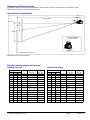
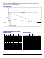
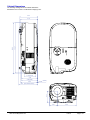
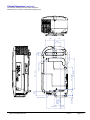
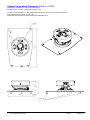
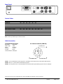
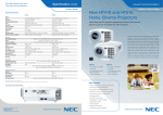
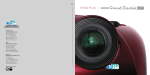
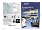
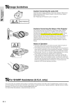
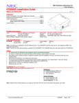
NEC Solutions (America), Inc.
Visual Systems Division
HT410 Installation Guide
Floor and Ceiling Configuration
v1.4
Contents
Product Description, Lens Specs, Screen/Aspect Ratio,
Notes and Formulas
Diagrams & Distance Charts; Ceiling Mounted
Floor
Cabinet Dimensions; Top, Front and Right
Bottom, Back and Left
Ceiling Mount Dimensions
Input Panel and Control Codes
Pg 1
Pg 2
Pg 3
Pg 4
Pg 5
Pg 6
Pg 7
Product Description
Type:
Resolution:
Brightness:
Contrast Ratio:
1 chip DMDTM projector
854 x 480 (16:9 native)
1000 ANSI Lumens
1200:1
Color Wheel: 5 Segments (2x)
Dimensions: 7.36”(W) x 5.24”(H) x 13.60”(D)
Weight:
6.6 lbs
Lens Specifications
Throw Ratio:
Offset Angle:
Screen Sizes:
1.65 - 1.96:1 (approximate)
Min. Lens Shift 5.5° - 6.5° (for 100” Diag)
Max. Lens Shift 13.5° - 16.0° (for 100” Diag)
30”-200” diagonal (16:9)
Manual Focus/Manual Zoom
Lens Shift: Vertical, Manual
Focal Length: 19.5mm – 23.0mm
F/#:
2.0 – 2.48
Notes
•
•
•
•
For screen sizes not indicated in the projection charts, use the formulas below.
The ceiling must be strong enough to support the projector and the installation must be in accordance with any local
building codes.
Distances are in inches, for millimeters multiply by 25.4.
Distances may vary ±5%.
Formulas
The Projection Formulas use the image width for calculation. For proper projector placement, determine the image width for a
desired screen size. Use the Screen Formulas below to calculate all screen dimensions. Plug in the image width for “W” in the
Projection Formulas.
Refer to the diagrams and charts for popular screen sizes on page 2.
Definitions:
W = Image Width
H = Image Height (Size)
B = Vertical distance between lens center and screen center
C = Throw distance
16:9 Screen Formulas:
W = H x 16/9
H = W x 9/16
Screen Diagonal = W x 18.35756/16
Projection Formulas:
B(min) = 0.1877W
B(max) = 0.4710W
C(wide) = 1.6695W – 1.913
C(tele) = 1.9801W – 1.883
-1
α(wide) = tan (B/C(wide))
α(tele) = tan-1 (B/C(tele))
Note: Factory preset is B(max)/maximum lens shift.
www.necvisualsystems.com
HT410
Page 1 of 7
Diagrams and Distance Charts
The following diagrams show the relationship between projector position and the screen. Refer to the chart below for data.
Distances are in inches. For millimeters multiply by 25.4.
Ceiling Mounted Configuration
6.6"
C
Throw Distance
5.5"
Lens Ctr
B(min)
B(max)
Lens Offset from
Mount Center
1.5"
*Factory Preset is B(max)
Note: Mount shown is NEC HT40CM.
Distance charts for popular 16:9 screens
Minimum Lens Shift
Screen Size (16:9)
Diag
W
26
B(min)
H
inches inches inches
30
Maximum Lens Shift
14.6
C
α
wide - tele
wide - tele
Screen Size (16:9)
Diag
inches
inches
degrees
4.9
41.5 - 49.6
6.7 - 5.6
30
W
inches inches inches
26
B(max)
H
14.6
C
α
wide - tele
wide - tele
inches
inches
degrees
12.2
41.5 - 49.6
16.4 - 13.9
55
48
27
9.0
78.2 - 93.2
6.6 - 5.5
55
48
27
22.6
78.2 - 93.2
16.1 - 13.6
60
52.5
29.5
9.9
85.7 - 102.1
6.6 - 5.5
60
52.5
29.5
24.7
85.7 - 102.1
16.1 - 13.6
73
64
36
12.0
104.9 - 124.8
6.5 - 5.5
73
64
36
30.1
104.9 - 124.8
16.0 - 13.6
82.6
72
40.5
13.5
118.3 - 140.7
6.5 - 5.5
82.6
72
40.5
33.9
118.3 - 140.7
16.0 - 13.6
92
80
45
15.0
131.6 - 156.5
6.5 - 5.5
92
80
45
37.7
131.6 - 156.5
16.0 - 13.5
100
87
49
16.3
143.3 - 170.4
6.5 - 5.5
100
87
49
41.0
143.3 - 170.4
16.0 - 13.5
106
92
52
17.3
151.7 - 180.3
6.5 - 5.5
106
92
52
43.3
151.7 - 180.3
15.9 - 13.5
110
96
54
18.0
158.4 - 188.2
6.5 - 5.5
110
96
54
45.2
158.4 - 188.2
15.9 - 13.5
119
104
58.5
19.5
171.7 - 204.0
6.5 - 5.5
119
104
58.5
49.0
171.7 - 204.0
15.9 - 13.5
133
116
65
21.8
191.7 - 227.8
6.5 - 5.5
133
116
65
54.6
191.7 - 227.8
15.9 - 13.5
161
140
79
26.3
231.8 - 275.3
6.5 - 5.5
161
140
79
65.9
231.8 - 275.3
15.9 - 13.5
200
174
98
32.7
288.6 - 342.7
6.5 - 5.4
200
174
98
82.0
288.6 - 342.7
15.9 - 13.5
www.necvisualsystems.com
HT410
Page 2 of 7
Diagrams and Distance Charts (cont.)
The following diagrams show the relationship between projector position and the screen. Refer to the chart below for data.
Distances are in inches. For millimeters multiply by 25.4.
Floor Configuration
C
Throw Distance
B(max)
B(min)
Lens Ctr
*Factory Preset is B(max)
Distance charts for popular 16:9 screens
Minimum Lens Shift
Screen Size (16:9)
Diag
W
26
B(min)
H
inches inches inches
30
Maximum Lens Shift
14.6
C
α
wide - tele
wide - tele
Screen Size (16:9)
Diag
inches
inches
degrees
4.9
41.5 - 49.6
6.7 - 5.6
30
W
inches inches inches
26
B(max)
H
14.6
C
α
wide - tele
wide - tele
inches
inches
degrees
12.2
41.5 - 49.6
16.4 - 13.9
55
48
27
9.0
78.2 - 93.2
6.6 - 5.5
55
48
27
22.6
78.2 - 93.2
16.1 - 13.6
60
52.5
29.5
9.9
85.7 - 102.1
6.6 - 5.5
60
52.5
29.5
24.7
85.7 - 102.1
16.1 - 13.6
73
64
36
12.0
104.9 - 124.8
6.5 - 5.5
73
64
36
30.1
104.9 - 124.8
16.0 - 13.6
82.6
72
40.5
13.5
118.3 - 140.7
6.5 - 5.5
82.6
72
40.5
33.9
118.3 - 140.7
16.0 - 13.6
92
80
45
15.0
131.6 - 156.5
6.5 - 5.5
92
80
45
37.7
131.6 - 156.5
16.0 - 13.5
87
49
41.0
143.3 - 170.4
16.0 - 13.5
100
87
49
16.3
143.3 - 170.4
6.5 - 5.5
100
106
92
52
17.3
151.7 - 180.3
6.5 - 5.5
106
92
52
43.3
151.7 - 180.3
15.9 - 13.5
110
96
54
18.0
158.4 - 188.2
6.5 - 5.5
110
96
54
45.2
158.4 - 188.2
15.9 - 13.5
119
104
58.5
19.5
171.7 - 204.0
6.5 - 5.5
119
104
58.5
49.0
171.7 - 204.0
15.9 - 13.5
133
116
65
21.8
191.7 - 227.8
6.5 - 5.5
133
116
65
54.6
191.7 - 227.8
15.9 - 13.5
161
140
79
26.3
231.8 - 275.3
6.5 - 5.5
161
140
79
65.9
231.8 - 275.3
15.9 - 13.5
200
174
98
32.7
288.6 - 342.7
6.5 - 5.4
200
174
98
82.0
288.6 - 342.7
15.9 - 13.5
www.necvisualsystems.com
HT410
Page 3 of 7
Cabinet Dimensions
The following drawings show the cabinet dimensions.
Dimensions are in inches. For millimeters multiply by 25.4.
4.94
13.27
13.60
4.76
3.17 (focus)
4.45
4.49 (boss)
4.69
0.0197 (button)
3.11
5.24 (from foot to button)
2.07
www.necvisualsystems.com
5.30
HT410
Page 4 of 7
Cabinet Dimensions (continued)
The following drawings show the cabinet dimensions.
Dimensions are in inches. For millimeters multiply by 25.4.
2.60
2.60
0.33 (lens)
M4x8 Max for Mount
1.12
(boss)
1.61
(foot)
3.86 (boss)
www.necvisualsystems.com
8.05 (boss)
1.77
5.81 (boss)
M4x8 Max for Mount
1.24
(foot)
9.94 (foot)
0.79
M4x8 Max for Mount
1.61
1.18
(boss)
HT410
Page 5 of 7
Optional Ceiling Mount Dimensions (Model #: HT40CM)
The following drawings show ceiling mount dimensions.
Dimensions are in inches. For millimeters multiply by 25.4.
The mount accommodates a 1.5” NPT treaded pipe extension or two 3/8”-16 threaded rod extensions.
Mount adjustments include roll, pitch and yaw.
Contact Peerless Industries for mount accessories at (800) 865-2112.
6.16
3.17
0.50
2.67
9.33
0.406
1.5" NPT
Standoffs
www.necvisualsystems.com
HT410
Page 6 of 7
Input Panel
PC CONTROL
S-VIDEO IN
Cb/Pb
Y
L
COMPUTER IN
Cr/Pr
AUDIO IN
COMPONENT IN
VIDEO IN
R
AUDIO IN
Control Codes
FUNCTION
POWER ON
POWER OFF
INPUT SELECT COMPUTER
INPUT SELECT COMPONENT
INPUT SELECT VIDEO
INPUT SELECT S-VIDEO
PICTURE MUTE ON
PICTURE MUTE OFF
SOUND MUTE ON
SOUND MUTE OFF
CODE DATA
02H
00H
02H
01H
02H
03H
02H
03H
02H
03H
02H
03H
02H
10H
02H
11H
02H
12H
02H
13H
00H
00H
00H
00H
00H
00H
00H
00H
00H
00H
00H
00H
00H
00H
00H
00H
00H
00H
00H
00H
00H
00H
02H
02H
02H
02H
00H
00H
00H
00H
02H
03H
01H
01H
01H
01H
12H
13H
14H
15H
01H
11H
06H
0BH
09H
19H
0EH
13H
Note: Checksum (CKS) is already included in the commands above.
Note: Contact your NEC rep for codes not listed.
Cable Connection
Communication Protocol:
Baud Rate:
38400 bps
Data Length:
8 bits
Parity:
No Parity
Stop Bit:
One bit
X on/off:
None
Communications: Full duplex
PC Control Connector (DIN-8P)
To RxD of PC
8
7
5
3
4
2
To GND of PC
6
1
To TxD of PC
NOTE 1: It is recommended to set the projector to “Idle Mode” in the Setup menu for best Power ON response.
NOTE 2: Pins 2, 3, 5, 6 and 8 are used inside the projector.
NOTE 3: For long cable runs it is recommended to set communication speed within projector menus to 9600 bps.
Digital Light Processing, DLP, Digital Micromirror Device and DMD are trademarks of Texas Instruments.
www.necvisualsystems.com
HT410
Page 7 of 7