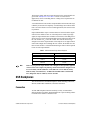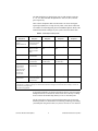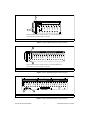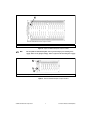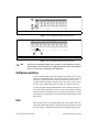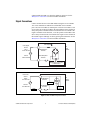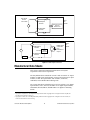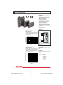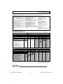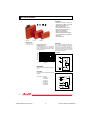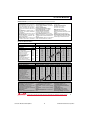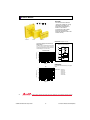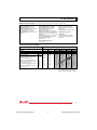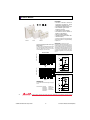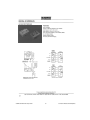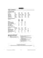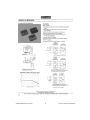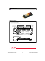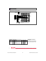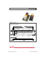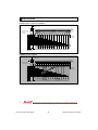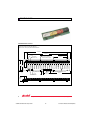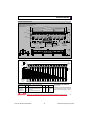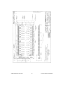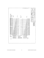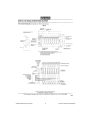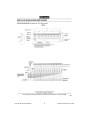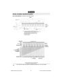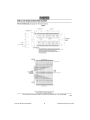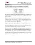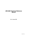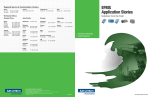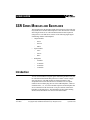
1
USER GUIDE SSR SERIES MODULES AND BACKPLANES This guide describes the mechanical and electrical aspects of the solid state relay (SSR) Series modules and backplanes. It also describes how to install and configure them for use with National Instruments data acquisition (DAQ) devices. The SSR Series consists of the following digital signal conditioning modules and backplanes: • • • Output modules – OAC5 – OAC5A – ODC5 Input modules – IAC5 – IAC5A – IDC5 Backplanes – 8-module – 16-module – 24-module – 32-module Introduction You can use the SSR Series digital signal conditioning modules with your PC and National Instruments DAQ devices to control or sense voltages from field devices. The SSR modules are high-performance, fully encapsulated devices that interface the PC to field devices via optical isolation. These modules plug into one of the SSR backplanes, which are available with 8-, 16-, 24-, and 32-module capacities. Each backplane has screw terminals for field connections. A 50-pin connector connects the backplane to the DAQ device. The backplanes also have light emitting diodes (LEDs) that indicate the status of each SSR module. Product and company names are trademarks or trade names of their respective companies. 371174A-01 © Copyright 1990, 1998 National Instruments Corp. All rights reserved. September 1998 What You Need to Get Started To set up and use the SSR Series modules and backplanes you need the following: ❑ SSR Series module backplane kit and documentation ❑ SSR Series module ❑ National Instruments DAQ device ❑ Cable and/or SC-205X device ❑ Number 1 and number 2 Phillips-head screwdrivers ❑ ¼ in. flat-head screwdriver Module Operation SSR modules optically isolate the field signals from the computer, preventing any possibility of damage to the computer by overvoltage transients on these lines. The optical isolation is rated for surges up to 4,000 V. Note All SSR modules use negative logic. Input Modules Input SSR modules sense voltages from a field source and return a logic value to the National Instruments DAQ device. If a voltage within the selected input range for the input module is present, it returns a logic low signal to the DAQ device, otherwise it returns a logic high signal. Output Modules Output SSR modules sense a logic value from the DAQ device to control external devices. They control power in a manner similar to conventional relays. If the DAQ device sends a logic low signal, the output module turns on and current flows. If the DAQ device sends a logic high signal, the output module turns off. Output SSR modules are similar to conventional relays, but there are some important differences. Unlike conventional relays, these solid state relays require voltage on the load side. Current needs to flow through them in the on state, or they turn off even if a logic low signal is at their input. This occurrence is referred to as dropout. If a solid state relay drops out, you must turn it off with a logic high signal before you can turn it on again. SSR Series Modules and Backplanes 2 © National Instruments Corporation The dropout voltage and current specifications for the output modules are given in the Manufacturer Data Sheets section. For most control applications, such as controlling motors or lamps, these requirements are not difficult to meet. A second difference between these output modules and conventional relays is that they do not turn off completely. A small leakage current flows all the time even in the off state. For most control applications, this current causes no problems. Output SSR modules require a certain amount of current from the digital control for the module to turn on. If the DAQ device sends a logic high signal, the output module turns off and no current flows. If the DAQ device sends a logic low signal, the output module turns on and current flows from the +DC control or Vcc to the -DC control. This current must be large enough to turn on the output module. If the DAQ device or digital control cannot sink enough current through the -DC control, the module does not turn on. Refer to Table 1 to find the minimum logic control current required to turn on each output module. Table 1. Minimum Control Logic Current Required Note Output Module Control Current ODC5 5 mA OAC5 12 mA OAC5A 12 mA Make sure you pair the output module with a DAQ device that provides sufficient control current. For example, the following National Instruments DAQ devices do not work reliably with the SSR-OAC-5 and SSR-OAC-5A: the DIO-24 (6503), DIO-96 (6508), Lab/1200 Series, AT-MIO-16D/AT-MIO-16DE extended DIO lines, DAQCard-700, PC-LPM-16, and PC-AO-2DC. SSR Backplanes This section describes the SSR backplane in detail including connection, function, SSR module installation, and field connections. Connection All four SSR backplanes function similarly, but they accommodate a different number of modules. Each backplane has a special cabling scheme to maximize the number of modules in use. © National Instruments Corporation 3 SSR Series Modules and Backplanes The SSR backplanes are divided into ports of eight modules each. The 8-, 16-, 24-, and 32-module backplanes have one, two, three, and four ports respectively. Table 2 shows backplanes that need an interface to convert the digital input/output (DIO) lines to map correctly. Table 2 also shows cables that are available for connecting DAQ devices and SSR backplanes. Refer to the National Instruments catalogue if your system is not listed in the table. Table 2. SSR Backplane Cabling Guide DAQ Device 8-Module Backplane 16-Module Backplane 24-Module Backplane 32-Module Backplane DIO-24 (6503) except DAQCard-DIO-24 NB1 cable or SC-205X adapter2 (via NB8 cable) NB1 cable NB1 cable NA DAQCard-DIO-24 PSH27-50F-D11 cable or SC-205X adapter (via NB8 cable) PSH27-50F-D11 cable PSH27-50F-D11 cable NA DIO-32HS (6533) SC-205X adapter2 (via NB8 cable) NA NA R6850-D1 cable1 DIO-96 (6508) SC-205X adapter2 (via NB8 cable) SC-205X adapter (via NB8 cable) SC-205X adapter (via NB8 cable) NA 50-pin MIO Series, 68-pin MIO E (60xx) Series, Lab/1200 Series, DAQCard-700, PC-LPM-16, PC-AO-2DC SC-205X adapter 2 (via NB8 cable) NA NA NA 100-pin MIO E (60xx) Series R1005050 cable1 or SC-205X adapter2 (via NB8 cable) R1005050 cable1 R1005050 cable1 NA 1These cables are available separately and are not included with the SSR Series backplane. adapter is available separately. See the National Instruments Catalogue for information about cabling to connect an SC-205X to your DAQ device. NA means not applicable 2This If you need an interface, use the SC-205X Series devices. You can connect backplanes that do not need an SC-205X Series device directly to a DAQ device because the modules map directly to one or more DIO ports. The SC-205X Series devices break out different DIO ports for use with different products. For information on connecting, mounting, and cabling your DIO ports using the SC-205X, see your SC-205X Series User Manual. SSR Series Modules and Backplanes 4 © National Instruments Corporation ! Caution Do not attempt to connect the SSR backplane to a host computer DAQ device for which it was not designed. Such connections can damage any or all SSR modules, the host computer, and the DAQ device. National Instruments is not liable for any damages resulting from incorrect connections. The 32-module backplane connects the PCLK1 (OUT1) and PCLK2 (OUT2) signals of the DIO-32HS (6533) device to ground. When using a 32- module backplane, do not configure a device for any mode that uses the PCLK1 or PCLK2 line. Specifically, do not configure the DIO-32HS (6533) for burst handshaking mode, which uses PCLK, or write any data to port 4, which is the port that includes the PCLK1 and PCLK2 lines. Incorrect configuration can damage the host computer and your DAQ device. National Instruments is not liable for any damages resulting from incorrect configuration. Configuring the Power Supply This section describes how to configure the SSR backplane jumpers to get +5 VDC power to the SSR modules. You can power the SSR module backplanes by either the DAQ device or an external power supply. You need external power when connecting to a DAQ device that does not supply external power or when the power needed for the SSR modules and any other accessories exceeds the power supplied by the DAQ device. Different DAQ devices supply different amounts of power; for example many supply 1 A. See the specifications of your device for more information. The current needed for the SSR modules and accessories is the sum of the maximum logic supply current of all SSR modules connected to the DAQ device plus any other current needed by accessories connected to the same DAQ device. To configure the SSR module backplane for external power or DAQ device power you need to set a jumper on the backplane. This can be just a wire jumper or it can be a fuse. If you use a wire jumper, you need to fuse the logic power supply somewhere before the backplane. Figures 1 through 7 show the backplane power jumper locations, which are not clearly marked on the backplane. Install only one jumper at a time. If you install both jumpers, you can damage the supply or SSR module backplane. © National Instruments Corporation 5 SSR Series Modules and Backplanes 1 - 25/49 16 15 14 13 12 11 10 9 8 7 6 5 4 3 2 1 + AC INPUT AC OUTPUT DC INPUT DC OUTPUT + Y B W R 2 1 0 2 3 4 5 6 7 Note: No External Power Jumper Locations, remove all DAQ device power jumpers for external power connection. 1 DAQ Device Power Jumper Location (use only one) 2 Not Used Figure 1. Grayhill 8 Module Backplane Jumper Locations 1 32 31 30 29 28 27 26 25 24 23 22 21 20 19 18 17 16 15 14 13 12 11 10 9 8 7 6 5 4 3 2 +– 1 Y AC INPUT B AC OUTPUT W DC INPUT R DC OUTPUT 0 1 2 3 4 5 6 7 8 9 10 11 12 13 14 15 2 Note: No External Power Jumper Locations, remove all DAQ device power jumpers for external power connection. 1 DAQ Device Power Jumper Location 2 Not Used Figure 2. Grayhill 16 Module Backplane Jumper Locations 33 32 31 15 16 34 30 29 14 35 28 27 13 17 36 26 25 24 12 37 23 11 18 38 22 21 10 39 20 19 9 19 40 18 17 8 41 16 15 7 42 14 13 12 11 10 9 8 7 6 5 4 3 2 1 1 6 20 43 2 5 21 44 4 45 3 22 46 2 – + 47 1 48 0 23 Y AC INPUT B AC OUTPUT W DC INPUT R DC OUTPUT 1 External Power Jumper 2 DAQ Device Power Jumper Figure 3. Grayhill 24 Module Backplane Jumper Locations SSR Series Modules and Backplanes 6 © National Instruments Corporation 1 Note: No DAQ Device Power Jumper Location 1 External Power Fuse Figure 4. Grayhill 32 Module Backplane Jumper Locations Note The Grayhill 32-module backplane can be powered only by an external power supply. There are no jumper settings. There is a fuse on the external power supply. 1 2 3 1 External Power Jumper 2 DAQ Device Power Jumper 3 Not Used Figure 5. Crouzet 8 Module Backplane Jumper Locations © National Instruments Corporation 7 SSR Series Modules and Backplanes 1 2 3 1 External Power Jumper 2 DAQ Device Power Jumper 3 Not Used Figure 6. Crouzet 16 Module Backplane Jumper Locations 1 1 2 External Power Jumper 2 DAQ Device Power Jumper Figure 7. Crouzet 24 Module Backplane Jumper Locations Note The Crouzet 32 module backplane has no position on the backplane for either a fuse or jumper. You must add a power supply fuse elsewhere before connecting the power. Use a fuse that is suitable for your application. SSR Module Installation You can install the SSR modules by plugging each module into one of the positions on an SSR backplane. They are keyed so they cannot be inserted incorrectly. Many DAQ devices require that all DIO lines in a port be configured either for input or output. In these cases make sure you install the same type of SSR module, input or output, for each line in the port. You can mix input and output SSR modules on the mounting rack only if you connect them to different I/O ports or you use a DAQ device that allows mixed line directions within a port. Do not attach input modules to output lines under any circumstances or you can damage the SSR modules or the DAQ device. LEDs Each module position of an SSR backplane has a status LED to show the status of the SSR module logic line. For input modules, the LED is on when the load voltage is within the specified range of the SSR module. For the SSR Series Modules and Backplanes 8 © National Instruments Corporation output modules the LED is on when the module is turned on. See the Manufacturer Data Sheets section for further information. Signal Connections Connect external devices to the SSR modules using the screw terminals. Two screw terminals are dedicated to each module. Screw terminal pair 1 and 2 are for module 0, terminal pair 3 and 4 are for module 1, and so on. In the case of the DC modules, the odd numbered screw terminal is always the positive terminal and the even numbered screw terminal is the negative terminal. On the load side, a 5 A fuse protects each module. This fuse is always located on the even numbered or negative screw terminal to the module. Figures 8 through 11 show typical signal connections. See the Manufacturer Data Sheets section for further information. IAC 5 (22 k ) IAC 5A (60 k ) User Signal Source IAC 5 90 to 140 VAC Odd Backplane Terminal IAC 5A 180 to 280 VAC Even Backplane Terminal AC Input Module 5A Digital Signal Conversion to DAQ Device Figure 8. IAC5 and IAC5A Signal Connections User Power Source 0AC 5 24 to 140 VAC AC Output Module Odd Backplane Terminal Snubber 0AC 5A 24 to 280 VAC Even Backplane Terminal Load Trigger Circuit 5A Figure 9. OAC5 and OAC5A Signal Connections © National Instruments Corporation 9 SSR Series Modules and Backplanes 1.8 k User Signal Source 3 to 32 VDC Odd Backplane Terminal + – Digital Conversion Signal to DAQ Device Input DC Module Even Backplane Terminal 5A Figure 10. IDC5 Signal Connections Odd Backplane Terminal + 80 VDC – Even Backplane Terminal Voltage Spike Protection Digital Signal Conversion from DAQ Device Output Output DC Module Load Figure 11. ODC5 Signal Connections Manufacturer Data Sheets This section contains the manufacturing data sheets of Grayhill Corporation1 and Crouzet Corporation2. The Grayhill data sheets include the 70-OAC5 and 70-OAC5A AC output modules; 70-ODC5 DC output module; 70-IAC5 and 70-IAC5A AC input modules; 70-IDC DC input module; and 70-RCK8, 70-RCK16, 70-RCK24, and 70-RCK32-HL mounting racks. The Crouzet data sheets include the IAC5, IAC5A, and IAC 0.6 in. digital input modules; OAC5, OAC5A, and ODC 0.6 in. digital output modules; and PB-8H, PB-16H, PB-24, and PB-32D 0.6 in. digital I/O mounting boards. 1 2 Copyright Grayhill, Inc. 1998. Reprinted with permission of the copyright owner. All rights reserved. Grayhill, Inc. Grayhill Control Products Catalog #7 Copyright Crouzet, Inc. 1996. Reprinted with permission of the copyright owner. All rights reserved. Crouzet, Inc. 1998/1999 Automation Controls Catalog SSR Series Modules and Backplanes 10 © National Instruments Corporation AC OUTPUT MODULES * FEATURES • Transient Protection: Meets the requirements of IEEE 472, “Surge Withstanding Capability Test” • SPST, Normally Open • Zero Crossing Turn-On • UL Recognized, CSA Certified • G5 Modules Passed IEC801.2, IEC801.3, and IEC801.4 • 4000 Vac Optical Isolation • G5 Modules Provide Replaceable 5 x 20 mm Glass Fuse and Built-in Status LED • Lifetime Warranty * •• TUV R h e i n l a n d 70G-OAC 70-OAC 70M-OAC CIRCUITRY Maximum Current Versus Ambient Temperature The chart indicates continuous current to limit the junction temperatures to 100˚C. Information is based on steady state heat transfer in a 2 cubic foot sealed enclosure. Fuse and Status LED in G5 modules only. LOAD 1 LOAD 2 VAC SNUBBER LOAD CURRENT (AMPS) 4 TRIGGER CIRCUIT STANDARD & G5 PACKAGE MINIATURE PACKAGE 3 2 Rx + 3 DC CONTROL – 1 - 40 - 20 0 20 40 60 80 AMBIENT TEMPERATURE (˚C) 4 Trigger circuit provides zero voltage turnon except for part numbers 70-OAC5A5 and 70-OAC5A-11, which have random (fast) turn-on. 100 Figure 1 PEAK SURGE CURRENT (AMPERES) Maximum Peak Surge Current Versus Surge Duration Information is based on a supply frequency of 60 Hz sinusoidal and a resistive or inductive load. Application of maximum surge current may not be repeated until the module temperature has returned to its steady state value. 300 200 100 80 60 40 30 20 DIMENSIONS For complete dimensional drawings, see pages 29-30. G5 FUSES Fuses are 5 Amp Littlefuse part number 217005 or equivalent. *Part Numbers: 70G-OAC5 70G-OAC5A 70G-OAC5A-11 70G-OAC15 70G-OAC15A 70G-OAC24 70G-OAC24A 10 6 4 3 1 1 1 2 3 4 6 10 20 40 60 100 1000 NUMBER OF FULL CYCLES AT 60 HERTZ Figure 2 32 An ISO-9001 Company 561 Hillgrove Avenue • LaGrange, Illinois 60525 • USA • Phone: (708) 354-1040 • Fax: (708) 354-2820 • http://www.grayhill.com © National Instruments Corporation 11 SSR Series Modules and Backplanes AC OUTPUT MODULES SPECIFICATIONS–All Modules Specifications apply over operating temperature range unless noted otherwise. Output Specifications Load Current Range (rms): 0.03 to 3.5 Amps for part numbers beginning 70 and 70G. 0.03 to 3.0 Amps for part numbers beginning 70M. Maximum current is limited by data noted in Figure 1. Maximum Surge Current (peak): 80 Amps at 60 Hz, 1 cycle; 25 Amps at 60Hz, 60 cycles as qualified by Figure 2. Maximum Zero Voltage Offset: 8 Vpeak Static dV/dT: 3000 volts per microsecond typical, measured under open circuit conditions; not to exceed peak blocking voltage. Turn-on Time (60 Hz): 8.3 mSec maximum (except 70-OAC5A5 which is 200 µSec and 70-OAC5A-11, 70M-OAC5A-11 and 70GOAC5A-11 which are 100 µSec) Turn-off Time (60 Hz): 8.3 mSec maximum On State Voltage Drop (peak): 1.5 volts max. Power Dissipation: 1.0 Watt/Amp typical Load Power Factor: 0.4 minimum Frequency Range: 25 to 70 Hz Thermal Resistance (RθJA): 25˚ C/Watt typical I 2t for Fusing (t = 8.3 mS): 35 A2 per Sec min. Mechanical Shock:1500 G?s 0.5 mS half-sine per MIL–STD–202, Method 213, Condition F Storage Temperature Range: -40˚C to +125˚C Operating Temperature Range: -40˚C to +100˚C Materials and Finishes General Characteristics Insulation Resistance (Input to Output; Input or Output to Case): ≥ 1010 Ohms Dielectric Strength Input to Output: 4000 Vac (rms) minimum Input to Output Capacitance: 6 pF typical Vibration: 20 G?s peak or .06” double amplitude 10–2000 Hz per MIL–STD–202, Method 204, Condition D Terminals: Copper wire, tin plated Case: Solvent resistant thermoplastic; meets UL94V–0 Potting: High thermal conductive epoxy UL Recognition and CSA Certification UL file number E58632 and CSA file number LR38763 apply to all modules shown here. SPECIFICATIONS BY PART NUMBER Standard and Miniature Modules Type/Function Grayhill Part Number Miniature, Normally Open, Random Turn-on Miniature, Normally Open, Zero Voltage Turn-on Standard, Normally Closed, Random Turn-on Standard, Normally Open, Random Turn-on Standard, Normally Open, Zero Voltage Turn-on Specifications 70M-OAC5A-11 70M-OAC5 70M-OAC5A 70M-OAC15 70M-OAC15A 70M-OAC24 70M-OAC24A 70-OAC5A5 70-OAC5A-11 70-OAC24A-11 70-OAC5 70-OAC5A 70-OAC15 70-OAC15A 70-OAC24 70-OAC24A Units Nominal Line Voltage Load Voltage Range Minimum Peak Blocking Voltage Maximum Off-state Leakage @ 60Hz. Nominal Logic Voltage (Vcc) Logic Voltage Range Max. Logic Supply Current @ Nominal Vcc Nominal Input Resistance (Rx) Minimum Drop Out Voltage Maximum Reverse Logic Voltage Vac Vac Volts mA, rms Vdc Vdc mA Ω Vdc Vdc 120 24-140 400 2 5 2.5-10 16 240 1 -5 240 24-280 600 4 5 2.5-10 16 240 1 -5 120 24-140 400 2 15 10-18 9 1800 1 -5 240 24-280 600 4 15 10-18 9 1800 1 -5 120 24-140 400 2 24 15-30 9 2700 1 -5 240 24-280 600 4 24 15-30 9 2700 1 -5 G5 Modules Grayhill Part Number Type/Function G5 Fusible, Normally Open, Zero Voltage Turn-on G5 Fusible, Normally Open, Random Turn-on Specifications 70G-OAC5 70G-OAC5A 70G-OAC15 70G-OAC15A 70G-OAC24 70G-OAC24A 70G-OAC5A-11 Units Nominal Line Voltage Load Voltage Range Minimum Peak Blocking Voltage Maximum Off-state Leakage @ 60Hz. Nominal Logic Voltage (Vcc) Logic Voltage Range Max. Logic Supply Current @ Nominal Vcc Nominal Input Resistance (Rx) Minimum Drop Out Voltage Maximum Reverse Logic Voltage Vac Vac Volts mA, rms Vdc Vdc mA Ω Vdc Vdc 120 24-140 400 2 5 4-6 20 100 1 -5 240 24-280 600 4 5 4-6 20 100 1 -5 120 24-140 400 2 15 8-20 12 1000 1 -5 240 24-280 600 4 15 8-20 12 1000 1 -5 120 24-140 400 2 24 18-32 8 2700 1 -5 240 24-280 600 4 24 18-32 8 2700 1 -5 Available from your local Grayhill Distributors For prices and discounts, contact a local Sales Office, an authorized local Distributor, or Grayhill. An ISO-9001 Company 561 Hillgrove Avenue • LaGrange, Illinois 60525 • USA • Phone: (708) 354-1040 • Fax: (708) 354-2820 • http://www.grayhill.com SSR Series Modules and Backplanes 12 33 © National Instruments Corporation DC OUTPUT MODULE * FEATURES • Transient Protection: Meets the requirements of IEEE 472, "Surge Withstanding Capability Test" • SPST, Normally Open • UL Recognized, CSA Certified • G5 Modules Passed IEC801.2, IEC801.3, and IEC801.4 • 4000 Vac Optical Isolation • G5 Modules Provide Replaceable 5 x 20 mm Glass Fuse and Built-in Status LED • Lifetime Warranty * •• TUV R h e i n l a n d 70G-ODC 70-ODC SEE CIRCUITRY AND DIMENSIONAL DRAWING FOR TERMINAL ID OF 70-ODC5R AND 70G-ODC5R. 70M-ODC CIRCUITRY Maximum Current Versus Ambient Temperature The chart indicates continuous current to limit the junction temperatures to 115˚C. Information is based on steady state heat transfer in a 2 cubic foot sealed enclosure. Two choices of switching speed vs. leakage current are offered. In applications where both AC and DC must be switched with the same module, use 70-ODC5R, 70M-ODC5R or 70G-ODC5R. These parts are dry contact relays in an I/O module shell. All other part numbers provide solid state switching. LOAD CURRENT (AMPS) 4 STANDARD & G5 PACKAGE 3 Solid State MINIATURE PACKAGE Fuse and Status LED in G5 modules only. 2 1 + 1 VOLTAGE SPIKE PROTECTION VDC – - 40 LOAD 200 VDC STYLE - 20 0 20 40 60 80 AMBIENT TEMPERATURE (˚C) LOAD 2 100 Figure 1 DIMENSIONS DRIVER CIRCUIT Rx + For complete dimensional drawings, see pages 29-30. G5 FUSES 3 DC CONTROL – 4 Dry Contact Fuses are 5 Amp Littlefuse part number 217005 or equivalent. *Part Numbers: 70G-ODC5 70G-ODC5A 70G-ODC5B 70G-ODC15 70G-ODC15B 70G-ODC24 70G-ODC24A 70G-ODC24B Fuse and Status LED in G5 modules only. LOAD LOAD An ISO-9001 Company 2 +VCC 3 AMP INPUT GROUND 34 1 VAC/VDC 4 5 561 Hillgrove Avenue • LaGrange, Illinois 60525 • USA • Phone: (708) 354-1040 • Fax: (708) 354-2820 • http://www.grayhill.com © National Instruments Corporation 13 SSR Series Modules and Backplanes DC OUTPUT MODULES SPECIFICATIONS Specifications apply over operating temperature range unless noted otherwise. Output Specifications Load Current Range: 0.02 to 3.5 Amps for part numbers beginning 70 and 70G; 0.02 to 3.0 Amps for 70M modules; 0.02 to 1.0 Amp for 70-ODC5A, 70M-ODC5A and 70G-ODC5A. Maximum current is limited by data noted in Figure 1. Power Dissipation:1.0 Watt/Amp typical; 1.5 Watt/Amp typ. for 70-ODC5A, 70M-ODC5A and 70G-ODC5A. Surge Current: 5 Amps maximum for 1 second On State Voltage Drop: 1.2 Volts maximum; 1.75 Volts maximum for 70-ODC5A, 70MODC5A and 70G-ODC5A. Clamping Voltage: 80 Vdc maximum; 360 Vdc maximum for 70-ODC5A, 70M-ODC5A and 70G-ODC5A. Thermal Resistance(RθJA): 20˚C/Watt typical Transient Power Dissipation: 400 Watts at 1 mS non-recurring General Characteristics Insulation Resistance (Input to Output; Input or Output to Case): ≥ 1010 Ohms Dielectric Strength Input to Output: Solid State: 4000 Vac (rms) minimum Dry Contact: 1500 Vac (rms) minimum Input to Output Capacitance: 10 pF typical Vibration: 20 G?s peak or .06" double amplitude 10–2000 Hz per MIL–STD–202, Method 204, Condition D Mechanical Shock: 1500 G?s 0.5 mS half-sine per MIL–STD–202, Method 213, Condition F Storage Temperature Range: -40˚C to +125˚C Operating Temperature Range: Solid State: -40˚C to +100˚C Dry Contact: -20˚C to +85˚C Materials and Finishes Terminals: Copper wire, tin plated Case: Solvent resistant thermoplastic; meets UL94V–0 Potting: High thermal conductive epoxy UL Recognition & CSA Certification UL file number E58632 and CSA file number LR38763 apply to all modules shown here. SPECIFICATIONS BY PART NUMBER–Solid State Modules Standard and Miniature Modules Type/Function Grayhill Part Number Miniature, Normally Open Standard, Normally Open 70M-ODC5 70M-ODC5A 70M-ODC5B 70M-ODC15 70M-ODC15B 70M-ODC24 70M-ODC24B 70-ODC5 70-ODC5A 70-ODC5B 70-ODC15 70-ODC15B 70-ODC24 70-ODC24B Specifications Units Maximum Line Voltage Load Voltage Range Max. Off-state Leakage @ 60 Vdc Maximum Turn-on Time Maximum Turn-off Time Nominal Logic Voltage (Vcc) Logic Voltage Range Max. Logic Supply Current @ Nominal Vcc Nominal Input Resistance (Rx) Minimum Drop Out Voltage Maximum Reverse Logic Voltage Vdc Vdc mA µSec µSec Vdc Vdc mA 60 3-60 1.5 20 50 5 2.5-10 14 200 4-200 .010 75 750 5 2.5-9 18 60 3-60 .010 75 500 5 2.5-10 14 60 3-60 1.5 20 50 15 10-18 9 60 3-60 .010 75 500 15 10-18 9 60 3-60 1.5 20 50 24 15-30 9 60 3-60 .010 75 500 24 15-30 9 Ω Vdc Vdc 300 1 -5 220 1 -5 300 1 -5 1800 1 -5 1800 1 -5 2700 1 -5 2700 1 -5 G5 Modules Grayhill Part Number Type/Function G5 Fusible, Normally Open 70G-ODC5 70G-ODC5A 70G-ODC5B 70G-ODC15 70G-ODC15B 70G-ODC24 70G-ODC24B Specifications Units Maximum Line Voltage Load Voltage Range Max. Off-state Leakage @ 60 Vdc Maximum Turn-on Time Maximum Turn-off Time Nominal Logic Voltage (Vcc) Logic Voltage Range Max. Logic Supply Current @ Nominal Vcc Nominal Input Resistance (Rx) Minimum Drop Out Voltage Maximum Reverse Logic Voltage Vdc Vdc mA µSec µSec Vdc Vdc mA 60 3-60 1.5 20 50 5 4-6 13 200 4-200 .010 75 750 5 4-6 13 60 3-60 0.01 75 500 5 4-6 13 60 3-60 1.5 20 50 15 10-20 9 60 3-60 0.01 75 500 15 10-20 9 60 3-60 1.5 20 50 24 18-32 9 60 3-60 0.01 75 500 24 18-32 9 Ω Vdc Vdc 150 1 -5 150 1 -5 150 1 -5 1500 1 -5 1500 1 -5 2700 1 -5 2700 1 -5 SPECIFICATIONS BY PART NUMBER–Dry Contact Modules 70-ODC5R, 70M-ODC5R and 70G-ODC5R Output Specifications Load Voltage: 100 Vdc/120 Vac maximum Contact Rating: 10 Watts maximum Switching Current: 0.5 A dc maximum. Inductive loads require diode suppression. Carry Current: 1.0 A maximum. Inductive loads require diode suppression. Life Expectancy: At 10 Vdc: 10 mA-200,000,000 operations min. An ISO-9001 Company At 48 Vdc: 100 mA-500,000 operations min. At 120 Vac: 80 mA-500,000 operations min. Contact Resistance: 250 mΩ maximum Turn-on Time: 1.0 mSec maximum (including bounce) Turn-off Time: 1.0 mSec maximum (including bounce) Off-State Leakage Current: 2 µA maximum at 60 Hz Input Specifications Nominal Logic Voltage: 5 Vdc Logic Voltage Range: 4.8-6.0 Vdc Max Logic Supply Current at Nominal Voltage: 10 mA Input Resistance: 500 Ω Pick Up Voltage: 0.8 Vdc minimum Drop Out Voltage: 2.5 Vdc minimum Reverse Logic Voltage: 5 Vdc maximum 561 Hillgrove Avenue • LaGrange, Illinois 60525 • USA • Phone: (708) 354-1040 • Fax: (708) 354-2820 • http://www.grayhill.com SSR Series Modules and Backplanes 14 35 © National Instruments Corporation AC INPUT MODULE * FEATURES • Transient Protection: Meets the requirements of IEEE 472, “Surge Withstanding Capability Test” • G5 Modules Passed IEC801.2, IEC801.3, and IEC801.4 • UL Recognized, CSA Certified • 4000 Vac Optical Isolation • G5 Module has Built-in Status LED • Lifetime Warranty * •• TUV R h e i n l a n d 70G-IAC 70-IAC 70M-IAC CIRCUITRY Typical Logic Supply Current Versus Logic Supply Voltage For Figures 1 and 2, all values were measured at 25˚C. The logic supply voltage continuum represents the voltage range for each of the three nominal voltages (5, 15, and 24 Vdc). Negative True Logic Status LED in G5 module only. Rx 1 VAC 2 LOGIC CURRENT (mA) Standard and Mini 10 +VCC 3 8 CURRENT REGULATING OUTPUT 6 INPUT VOLTAGE HYST. CIRC. 4 GROUND 5 4 3 8 15 5 15 24 6 18 30 LOGIC SUPPLY VOLTAGE (VDC) Figure 1 DIMENSIONS For complete dimensional drawings, see pages 29-30. G5 12 *Part Numbers: 70G-IAC5 70G-IAC5A 70G-IAC15 70G-IAC15A 70G-IAC24 70G-IAC24A LOGIC CURRENT (mA) 10 8 6 4 4.5 10 17 5.25 14.0 23 6 18 30 LOGIC SUPPLY VOLTAGE (VDC) Figure 2 38 An ISO-9001 Company 561 Hillgrove Avenue • LaGrange, Illinois 60525 • USA • Phone: (708) 354-1040 • Fax: (708) 354-2820 • http://www.grayhill.com © National Instruments Corporation 15 SSR Series Modules and Backplanes AC INPUT MODULE SPECIFICATIONS–All Modules Specifications apply over operating temperature range unless noted otherwise. Output Specifications General Characteristics Materials and Finishes Output Current Range: 1-50 mA Breakdown Voltage: 50 Vdc minimum Off-State Leakage Current: 1 µA maximum Turn-on Time: 20 mSec maximum Turn-off Time: 20 mSec maximum On State Voltage Drop: 0.45 Vdc at 50 mA maximum Insulation Resistance (Input to Output; Input or Output to Case): ≥ 1010 Ohms Dielectric Strength Input to Output: 4000 Vac (rms) minimum Input to Output Capacitance: 6 pF typical Vibration: 20 G?s peak or .06" double amplitude 10–2000 Hz per MIL–STD–202, Method 204, Condition D Mechanical Shock: 1500 G?s 0.5 mS half-sine per MIL–STD–202, Method 213, Condition F Storage Temperature Range: -40˚C to +125˚C Operating Temperature Range: -40˚C to +100˚C Terminals: Copper wire, tin plated Case: Solvent resistant thermoplastic; meets UL94V–0 Potting: High thermal conductive epoxy UL Recognition and CSA Certification UL file number E58632 and CSA file number LR38763 apply to all modules shown here. SPECIFICATIONS BY PART NUMBER Type/Function Grayhill Part Number G5, Status LED Miniature Standard 70G-IAC5 70M-IAC5 70-IAC5 Specifications 70G-IAC5A 70M-IAC5A 70-IAC5A 70G-IAC15 70M-IAC15 70-IAC15 70G-IAC24 70M-IAC24 70-IAC24 70G-IAC24A 70M-IAC24A 70-IAC24A Units Nominal Input Voltage Input Voltage Range* Input Current at Maximum Input Voltage Nominal Input Resistance (Rx) Maximum Pick Up Voltage (Output Low) Minimum Drop Out Voltage (Output High) Nominal Logic Voltage (Vcc) Logic Voltage Range: Standard and Mini G5 Max. Logic Supply Current @ Nominal Vcc (See Figure 1 or 2) Vac Vac/Vdc mA, rms Ω Vac Vac Vdc Vdc Vdc mA 120 90-140 8 22K 90 25 5 3-6 4.5-6 10 240 180-280 6 60K 180 50 5 3-6 4.5-6 10 120 90-140 8 22K 90 25 15 8-18 10-18 10 * For input voltages in the range of 15-32 Vac, or 35-60 Vac, see DC input Modules with the NP or G suffix. An ISO-9001 Company 70G-IAC15A 70M-IAC15A 70-IAC15A 240 180-280 6 60K 180 50 15 8-18 10-18 10 120 90-140 8 22K 90 25 24 15-30 17-30 10 240 180-280 6 60K 180 50 24 15-30 17-30 10 Available from your local Grayhill Distributors For prices and discounts, contact a local Sales Office, an authorized local Distributor, or Grayhill. 561 Hillgrove Avenue • LaGrange, Illinois 60525 • USA • Phone: (708) 354-1040 • Fax: (708) 354-2820 • http://www.grayhill.com SSR Series Modules and Backplanes 16 39 © National Instruments Corporation DC INPUT MODULE * FEATURES • Transient Protection: Meets the requirements of IEEE 472, “Surge Withstanding Capability Test”** • Fast Switching Polarized Input Types • Non-Polarized Types Provide Inputs For AC or DC • UL Recognized, CSA Certified • G5 Modules Passed IEC801.2, IEC801.3, and IEC801.4 • 4000 Vac Optical Isolation • G5 Module has Built-in Status LED • Lifetime Warranty * •• TUV R h e i n l a n d 70G-IDC 70-IDC **All modules except 70-IDC5B, 70G-IDC5B, and 70G-IDC5D meet IEEE 472, "Surge Withstanding Capability Test" 70M-IDC CIRCUITRY Typical Logic Supply Current Versus Logic Supply Voltage For Figures 1 and 2, all values were measured at 25˚C. The logic supply voltage continuum represents the voltage range for each of the three nominal voltages (5, 15, and 24 Vdc). Negative True Logic Modules have either a polarized (Figure 3) or nonpolarized (Figure 4) input. When replacing modules from another manufacturer, check the wiring diagrams below against the application circuit. In many instances, polarized modules can be used to replace non-polarized modules if the polarity matches the application, thus providing faster turn-on. LOGIC CURRENT (mA) Standard and Mini 10 DC INPUT Status LED in G5 module only. 8 Rx + 6 1 VDC – 4 3 8 15 5 15 24 6 18 30 LOGIC SUPPLY VOLTAGE (VDC) 2 +VCC INPUT VOLTAGE HYST. CIRC. 3 Figure 1 LOGIC CURRENT (mA) G5 CURRENT REGULATING OUTPUT 4 10 GROUND 5 8 Figure 3: With Polarized Input 6 4 4.5 10 17 5.25 14.0 23 6 18 30 DC OR AC INPUT Status LED in G5 module only. Rx 1 LOGIC SUPPLY VOLTAGE (VDC) VAC Figure 2 2 DIMENSIONS For complete dimensional drawings, see pages 29-30. *Part Numbers: 70G-IDC5 70G-IDC5B 70G-IDC5G 70G-IDC5NP 70G-IDC5S 70G-IDC15 70G-IDC15NP 70G-IDC24 70G-IDC24NP +VCC 3 INPUT VOLTAGE HYST. CIRC. CURRENT REGULATING OUTPUT 4 GROUND 5 Figure 4: With Non-Polarized (NP) Input 40 An ISO-9001 Company 561 Hillgrove Avenue • LaGrange, Illinois 60525 • USA • Phone: (708) 354-1040 • Fax: (708) 354-2820 • http://www.grayhill.com © National Instruments Corporation 17 SSR Series Modules and Backplanes DC INPUT MODULE SPECIFICATIONS–All Modules Specifications apply over operating temperature range unless noted otherwise. Output Specifications General Characteristics Materials and Finishes Output Current Range: 1-50 mA Breakdown Voltage: 50 Vdc minimum Off State Leakage Current: 1 µA maximum On State Voltage Drop: 0.45 Vdc at 50 mA maximum Storage Temperature Range: -40˚C to +125˚C Operating Temperature Range: -40˚C to +100˚C Insulation Resistance (Input to Output; Input or Output to Case): ≥ 1010 Ohms Dielectric Strength Input to Output: 4000 Vac (rms) minimum Input to Output Capacitance: 6 pF typical Vibration: 20 G?s peak or .06" double amplitude 10–2000 Hz per MIL–STD–202, Method 204, Condition D Mechanical Shock: 1500 G?s 0.5 mS half-sine per MIL–STD–202, Method 213, Condition F Terminals: Copper wire, tin plated Case: Solvent resistant thermoplastic; meets UL94V–0 Potting: High thermal conductive epoxy UL Recognition & CSA Certification UL file number E58632 and CSA file number LR38763 apply to all modules shown here, except 70-IDC5B and 70M-IDC5NP. SPECIFICATIONS–By Part Number (DC Input Only) Type/Function Grayhill Part Number G5, Polarized Miniature, Polarized Standard, Polarized 70G-IDC5 70M-IDC5 70-IDC5 Specifications Units Maximum Input Voltage Input Voltage Range* Input Current at Max. Input Voltage Maximum Turn-on Time Maximum Turn-off Time Nominal Input Resistance (Rx) Max. Pick Up Voltage (Output Low) Min. Drop Out Voltage (Output High) Nominal Logic Voltage (Vcc) Logic Voltage Range: Std & Mini G5 Max. Logic Supply Current @ Nominal Vcc (See Figure 1 or 2) Vdc Vdc mA mSec mSec Ω Vdc Vdc Vdc Vdc Vdc mA 70G-IDC5B 70G-IDC5D 70G-IDC5K 70-IDC5B 32 3-32 18 0.20 0.40 1.8K 3 1 5 3-6 4.5-6 10 32 3-32 18 0.050 0.075 1.8K 3 1 5 3-6 4.5-6 18 28 2.5-28 23 0.050 0.075 1.2K 2.5 1 5 16 2.5-16 30 0.025 0.025 500 2.5 1 5 4.5-6 10 4.5-6 18 70G-IDC15 70M-IDC15 70-IDC15 32 3-32 18 0.20 0.40 1.8K 3 1 15 8-18 10-18 10 70G-IDC24 70M-IDC24 70-IDC24 32 3-32 18 0.20 0.40 1.8K 3 1 24 15-30 17-30 10 SPECIFICATIONS–By Part Number (AC or DC Input) Type/Function Grayhill Part Number G5, Non-Polarized Miniature, Non-Polarized Standard, Non-Polarized Specifications 70G-IDC5G 70M-IDC5G 70-IDC5G 70G-IDC5NP 70M-IDC5NP 70-IDC-5NP 70G-IDC15NP 70G-IDC24NP 70-IDC15NP 70-IDC24NP 60 35-60 6 10 10 10K 35 9 5 3-6 4.5-6 10 32 15-32/10-32 25 5 5 1.8K 15/10 3 5 3-6 4.5-6 10 28 15-32/10-32 25 5 5 1.8K 15/10 3 15 8-18 10-18 10 32 15-32/10-32 25 5 5 1.8K 15/10 3 24 15-30 17-30 10 Units Maximum Input Voltage Input Voltage Range* Input Current at Max. Input Voltage Maximum Turn-on Time Maximum Turn-off Time Nominal Input Resistance (Rx) Max. Pick Up Voltage (Output Low) Min. Drop Out Voltage (Output High) Nominal Logic Voltage (Vcc) Logic Voltage Range: Std & Mini G5 Max. Logic Supply Current @ Nominal Vcc (See Figure 1 or 2) Vac/Vdc Vac/Vdc mA mSec mSec Ω Vac/Vdc Vac/Vdc Vdc Vdc Vdc mA * For input voltages in the range of 90 to 140 Vdc, use AC input modules 70-IAC5, 70M-IAC5 or 70G-IAC5. For input voltages in the range of 180 to 280 Vdc, use AC input modules 70-IAC5A, 70M-IAC5A or 70G-IAC5A. An ISO-9001 Company Available from your local Grayhill Distributors For prices and discounts, contact a local Sales Office, an authorized local Distributor, or Grayhill. 561 Hillgrove Avenue • LaGrange, Illinois 60525 • USA • Phone: (708) 354-1040 • Fax: (708) 354-2820 • http://www.grayhill.com SSR Series Modules and Backplanes 18 41 © National Instruments Corporation © National Instruments Corporation 19 SSR Series Modules and Backplanes SSR Series Modules and Backplanes 20 © National Instruments Corporation © National Instruments Corporation 21 SSR Series Modules and Backplanes SSR Series Modules and Backplanes 22 © National Instruments Corporation MOUNTING RACKS 8 MODULE RACK–Standard Part No. 70RCK8 Schematic and Ordering Information on page 54. Dimensions are shown in inches (and millimeters). All tolerances are ± 0.010 (0,25) unless otherwise specified. 8.00 (203,2) TERMINAL STRIP FOR LOGIC SUPPLY 16 15 14 13 12 11 10 9 8 7 6 5 4 3 2 1 + KEY SLOT PINS 5/7 3.00 (76,2) + 1 AC INPUT AC OUTPUT DC INPUT DC OUTPUT 1 + 0.30 (7,6) PIN 1 0 1 2 USER INSTALLABLE JUMPERS FOR +VCC (3 PLACES) 0.40 (10,2) 3.50 (88,9) Y B W R 1.40 (35,6) 2.60 (66,0) TERMINAL STRIP FOR FIELD WIRING - + 25/49 0.45 (11,4) STANDOFF I.D. 0.15 (3,8) DIA. (4 PLACES) CLEARANCE FOR #6 SCREW 7.50 (190,5) CARD EDGE OR HEADER CONNECTOR FOR LOGIC SIGNALS. (SEE NOTES) 3 4 5 6 7 0.25 (6,4) 0.25 (6,4) 2.20 (55,9) MAX. 0.75 (19,1) 52 An ISO-9001 Company 561 Hillgrove Avenue • LaGrange, Illinois 60525 • USA • Phone: (708) 354-1040 • Fax: (708) 354-2820 • http://www.grayhill.com © National Instruments Corporation 23 SSR Series Modules and Backplanes MOUNTING RACKS SCHEMATIC–Part Nos. 70RCK8, 70MRCK8 LOGIC SUPPLY TERMINAL STRIP – • • • 26 24 22 20 18 16 14 12 10 8 6 4 2 25 23 21 19 17 15 13 11 9 7 N/C 5 N/C 3 N/C 1 26 PIN EDGE CONNECTOR FOR LOGIC SIGNALS 50 48 46 44 42 40 38 36 34 32 30 28 26 24 22 20 18 16 14 12 10 8 6 4 2 49 47 45 43 41 39 37 35 33 31 29 27 25 23 21 19 17 15 13 11 9 7 5 3 1 54 Part Number I/O 70RCK8 70RCK8-HL 70MRCK8-EC 70MRCK8-HL 70GRCK8-HL 8 8 8 8 8 2 1 2 3 4 5 0 3 4 6 7 8 9 10 11 12 13 14 15 16 FIELD WIRING TERMINAL STRIP 5A FUSE 1 2 3 4 5 6 7 N/C N/C N/C N/C N/C N/C N/C N/C N/C N/C N/C N/C N/C N/C 3.3K USER INSTALLABLE JUMPERS FOR +VCC (3 PLACES) ENGINEERING INFORMATION (modules ordered separately) Description UL Card edge 50 Pin header with ejector levers Card edge 50 Pin header with ejector levers 50 Pin header with ejector levers X X X X X An ISO-9001 Company 5 MODULE POSITION 50 PIN EDGE OR HEADER CONNECTOR FOR LOGIC SIGNALS ORDERING INFORMATION 1 + CSA X X X X X Style Standard Standard Mini Mini G5 See pages 48-49. Available from your local Grayhill Distributor For prices and discounts, contact a local Sales Office, an authorized local Distributor, or Grayhill. 561 Hillgrove Avenue • LaGrange, Illinois 60525 • USA • Phone: (708) 354-1040 • Fax: (708) 354-2820 • http://www.grayhill.com SSR Series Modules and Backplanes 24 © National Instruments Corporation MOUNTING RACKS 16 MODULE RACK–Standard Part No. 70RCK16 Schematic and Ordering Information on pages 58-59. Dimensions are shown in inches (and millimeters). All tolerances are ± 0.010 (0,25) unless otherwise specified. 14.05 (356,9) 0.25 (6,4) 13.55 (344,2) 50 PIN EDGE CARD OR HEADER CONNECTOR FOR LOGIC SIGNALS (SEE NOTES) 0.40 (10,2) 5A FUSE FIELD WIRING TERMINAL STRIP LOGIC SUPPLY TERMINAL STRIP 0.45 (11,4) 32 31 30 29 28 27 26 25 24 23 22 21 20 19 18 17 16 15 14 13 12 11 10 9 8 7 6 5 4 3 2 1 +– 3.50 (88,9) 2.60 (66,0) 3.00 (76,2) Y AC INPUT B AC OUTPUT W DC INPUT R DC OUTPUT 0 KEY SLOT PINS 11/13 1 2 3 4 5 6 7 8 PIN 1 USER INSTALLABLE JUMPER FOR +VCC (2 PLACES) STATUS LED 9 10 11 12 13 14 STANDOFF I.D. 0.15 (3,8) DIA. (4 PLACES) CLEARANCE FOR #6 SCREWS 15 0.25 (6,4) 2.20 (55,9) MAX. 0.75 (19,1) An ISO-9001 Company 561 Hillgrove Avenue • LaGrange, Illinois 60525 • USA • Phone: (708) 354-1040 • Fax: (708) 354-2820 • http://www.grayhill.com © National Instruments Corporation 25 55 SSR Series Modules and Backplanes MOUNTING RACKS SCHEMATIC–Part Nos. 70RCK16 and 70MRCK16 LOGIC SUPPLY TERMINAL STRIP – + USER INSTALLABLE JUMPER FOR +VCC (2 PLACES) 50 48 46 44 42 40 38 36 34 32 30 28 26 24 22 20 18 16 14 12 10 8 6 4 2 49 47 45 43 41 39 37 35 33 31 29 27 25 23 21 19 17 15 13 11 9 7 5 3 1 1 2 1 2 3 4 5 0 3 4 5 6 7 8 9 10 11 12 13 14 15 16 17 18 19 20 21 22 23 24 25 26 27 28 29 30 31 32 FIELD WIRING TERMINAL STRIP 5A FUSE 1 2 3 4 5 6 7 8 9 10 11 12 13 14 15 MODULE POSITION N/C N/C N/C N/C N/C N/C N/C 3.3K 50 PIN EDGE OR HEADER CONNECTOR FOR LOGIC SIGNALS SCHEMATIC–Part No. 70GRCK16 LOGIC SUPPLY TERMINAL STRIP – + 1 A FUSE USER INSTALLABLE JUMPER FOR +VCC 50 48 46 44 42 40 38 36 34 32 30 28 26 24 22 20 18 16 14 12 10 8 6 4 2 49 47 45 43 41 39 37 35 33 31 29 27 25 23 21 19 17 15 13 11 9 7 5 3 1 1 2 1 2 3 4 5 0 3 4 1 5 6 2 7 8 3 9 10 11 12 13 14 15 16 17 18 19 20 21 22 23 24 25 26 27 28 29 30 31 32 FIELD WIRING TERMINAL STRIP 4 5 6 7 8 9 10 11 12 13 14 15 MODULE POSITION N/C N/C N/C N/C N/C N/C N/C 3.3K 50 PIN HEADER CONNECTOR FOR LOGIC SIGNALS 58 An ISO-9001 Company 561 Hillgrove Avenue • LaGrange, Illinois 60525 • USA • Phone: (708) 354-1040 • Fax: (708) 354-2820 • http://www.grayhill.com SSR Series Modules and Backplanes 26 © National Instruments Corporation MOUNTING RACKS 24 MODULE RACK–Standard Part No. 70RCK24 Dimensions are shown in inches (and millimeters). Tolerances are ± 0.010 (0,25) unless indicated otherwise. 18.75 (476,3) 16.50 (419,1) 11.00 (279,4) STANDOFF I.D. 0.15 (3,8) DIA. (8 PLACES) CLEARANCE FOR #6 SCREWS 5.50 (139,7) 1.12 (28,4) 47 46 45 44 43 42 41 40 39 38 37 36 35 34 33 32 31 30 29 28 27 26 25 24 23 22 21 20 19 FIELD WIRING TERMINAL STRIP 48 5A FUSE 18 17 16 15 14 13 12 11 10 9 8 7 6 5 4 3 2 1 4.50 (114,3) 4.00 (101,6) 0 1 2 – + 3 4 5 6 7 8 9 10 11 12 13 14 15 16 17 18 19 20 21 22 23 Y AC INPUT B AC OUTPUT W DC INPUT R DC OUTPUT SOCKETS FOR OPTIONAL 1A FUSE 0.25 (6,4) 1A FUSE LOGIC SUPPLY TERMINAL STRIP 0.40 (10,2) KEY SLOT PINS 23/25 2.60 (66,0) 50 PIN EDGE CARD OR HEADER CONNECTOR FOR LOGIC SIGNALS (SEE NOTES) 8.08 (205,2) 1.00 (25.4) (2 PLACES) 2.20 (55,9) MAX. 0.75 (19,1) 60 An ISO-9001 Company 561 Hillgrove Avenue • LaGrange, Illinois 60525 • USA • Phone: (708) 354-1040 • Fax: (708) 354-2820 • http://www.grayhill.com © National Instruments Corporation 27 SSR Series Modules and Backplanes MOUNTING RACKS 24 MODULE RACK–Miniature Part No. 70MRCK24 Dimensions are shown in inches (and millimeters). All tolerances are ± 0.010 (0,25) unless otherwise specified. 13.45 (341,6) 12.00 (304,8) FIELD WIRING TERMINAL STRIPS (3 PLACES) 8.00 (203,2) 5A FUSE 0.35 (8,9) 33 34 35 36 37 38 39 40 41 42 43 44 45 46 47 48 1 2 3 4 5 6 7 8 9 10 11 12 13 14 15 16 17 18 19 20 21 22 23 24 25 26 27 28 29 30 31 32 4.00 (101,6) 0.73 (18,5) 3.75 (95,3) 3.05 (77,5) STATUS LED 0 1 2 3 – 4 5 6 7 8 9 10 11 0 1 2 3 4 5 6 7 + SOCKETS FOR OPTIONAL 1A FUSE LOGIC SUPPLY TERMINAL STRIP Y B W R 8 9 10 AC INPUT AC OUTPUT DC INPUT DC OUTPUT PIN 1 50 PIN EDGE CARD OR HEADER CONNECTOR FOR LOGIC SIGNALS (SEE NOTE) 2.60 (66,0) 5.42 (137,7) STANDOFF I.D. 0.15 (3,8) DIA. (8 PLACES) CLEARANCE FOR #6 SCREWS 0.40 (10,2) KEY SLOT PINS 23/25 1A FUSE 11 MODULE HOLD DOWN STRIP WITH THUMB SCREWS 2.20 (55,9) MAX. 0.75 (19,1) SCHEMATIC–Part Nos. 70RCK24 and 70MRCK24 LOGIC SUPPLY TERMINAL STRIP – + 1 2 3 4 5 6 7 8 1A OPTIONAL 1A FUSE 50 48 46 44 42 40 38 36 34 32 30 28 26 24 22 20 18 16 14 12 10 8 6 4 2 1 2 3 4 5 49 47 45 43 41 39 37 35 33 31 29 27 25 23 21 19 17 15 13 11 9 7 5 3 1 50 PIN EDGE CARD OR HEADER CONNECTOR FOR LOGIC SIGNALS FIELD 9 10 11 12 13 14 15 16 17 18 19 20 21 22 23 24 25 26 27 28 29 30 31 32 33 34 35 36 37 38 39 40 41 42 43 44 45 46 47 48 WIRING TERMINAL STRIP 5A 0 1 2 3 4 5 6 7 8 9 11 12 13 14 15 16 17 18 19 20 21 22 23 MODULE POSITION 3.3K ORDERING INFORMATION ENGINEERING INFORMATION (modules ordered separately) Part Number I/O Description UL 70RCK24 70RCK24-HL 70MRCK24-EC 70MRCK24-HL 24 24 24 24 Card edge 50 Pin header with ejector levers Card edge 50 Pin header with ejector levers X X X X An ISO-9001 Company 10 CSA X X X X Style Standard Standard Mini Mini See pages 48-49. Available from your local Grayhill Distributor For prices and discounts, contact a local Sales Office, an authorized local Distributor, or Grayhill. 561 Hillgrove Avenue • LaGrange, Illinois 60525 • USA • Phone: (708) 354-1040 • Fax: (708) 354-2820 • http://www.grayhill.com SSR Series Modules and Backplanes 28 61 © National Instruments Corporation © National Instruments Corporation 29 SSR Series Modules and Backplanes SSR Series Modules and Backplanes 30 © National Instruments Corporation © National Instruments Corporation 31 SSR Series Modules and Backplanes SSR Series Modules and Backplanes 32 © National Instruments Corporation © National Instruments Corporation 33 SSR Series Modules and Backplanes SSR Series Modules and Backplanes 34 © National Instruments Corporation