1
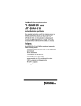
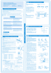
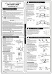
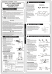
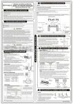
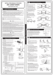
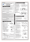
OPERATING INSTRUCTIONS
FP-QUAD-510
4-Axis, Quadrature Input Module
These operating instructions describe the installation, features, and
characteristics of the FP-QUAD-510. For details on configuring
and accessing the FP-QUAD-510 over a network, refer to the user
manual for the particular FieldPoint network module you are using
with the FP-QUAD-510.
Features
The FP-QUAD-510 is a FieldPoint quadrature input module with
the following features:
•
Four independent 32-bit position counters with individual
Phase A, Phase B, and Index input terminals
•
Velocity measurement capabilities
•
Programmable reset on index mode
•
Sinking inputs, compatible with TTL or differential devices
•
Inputs protected to ±250 VDC
•
Hot plug and play operation
•
2,500 Vrms input-to-output isolation
•
Double insulated for 250 V safe working voltage
Power Requirement
The FP-QUAD-510 is powered via the local backplane bus from
the FieldPoint network module. The FP-QUAD-510 is a
high-power consumption module and requires more than the
nominal power allocated to an I/O module from the network
module. In some applications, this could limit the number of I/O
modules that you can connect to a single network module.
FieldPoint™, National Instruments™, and ni.com™ are trademarks of National Instruments Corporation. Product and
company names mentioned herein are trademarks or trade names of their respective companies.
322633B-01
© Copyright 2000 National Instruments Corp. All rights reserved.
March 2000
When defining a FieldPoint system that uses an FP-QUAD-510
module, you must calculate the power consumption. First refer
to the specifications section in the user manual for your network
module. The maximum number of terminal bases per bank
multiplied by 1 watt is the total power the network module can
supply. For example, an FP-1000 or FP-1001 can support nine
terminal bases (9 × 1 W = 9 W).
Next, refer to the specifications section in the operating
instructions for the I/O modules. Use the Power from Network
Module specification. For example, a bank of modules consisting
of four FP-QUAD-510 and five FP-DI-301 modules requires a total
of 6.4 W from the FieldPoint network module [4 × (1.2 W) + 5 ×
(0.325 W) = 6.4 W]. This power requirement is less than the 9 W
maximum and is therefore acceptable.
Installation
The FP-QUAD-510 mounts on a FieldPoint terminal base
(FP-TB-xx) unit. Because of its hot plug and play operation, you
can install the FP-QUAD-510 onto a powered terminal base
without disturbing the operation of other modules or terminal
bases. Although the FP-QUAD-510 receives operating power from
the terminal base, the input circuitry requires an external power
supply.
To install your module, refer to Figure 1 and complete the
following steps:
1. Slide the terminal base key to either position 8 (used for the
FP-QUAD-510 module) or position X (used for any module).
Note Although your module operates normally with the
terminal base key in either position, you should use the
position specifically for your module whenever possible.
By doing so, you avoid accidentally plugging an incorrect
module into a base once the base has been wired into the
system.
2. Align the FP-QUAD-510 alignment slots with the guide rails
on the terminal base.
3. Press firmly to seat the FP-QUAD-510 on the terminal base.
When the module is firmly seated, the terminal base latch locks
it into place.
FP-QUAD-510
2
www.ni.com
Key
Latch
Alignment
Slot
Guide Rails
I/O Module
Terminal Base
Figure 1. Install Your Module
Field Wiring
The terminal base provides connections for each axis and for an
external supply to power the FP-QUAD-510 input channels and
field devices.
The FP-QUAD-510 accepts two types of encoder signal inputs:
single-ended (TTL) or differential line driver. Figure 2 shows the
typical encoder wiring for differential signal input. Figure 3 shows
the typical encoder wiring for single-ended signal input. Power for
a +5 V encoder is also provided for each axis. If you require other
encoder power voltages, reference an external supply to either the
C terminal or the COM terminal.
–
C
+
V
Encoder
+5 V
Reg
Vsup
+A
–A
+B
–B
+I
–I
COM
+5 V
+A
–A
+B
–B
+Index
–Index
GND
Figure 2. Basic Field Connections to Differential Encoders
© National Instruments Corp.
3
FP-QUAD-510
–
C
+
V
Encoder
+5 V
Reg
Vsup
+5 V
+A
–A
NC
+B
–B
NC
+I
–I
NC
+A
+B
+Index
COM
GND
Figure 3. Basic Field Connections to Single-Ended Encoders
The FP-QUAD-510 supports differential inputs for Phase A,
Phase B, and Index signals. You can easily accommodate encoders
with various phase relationships by swapping the signals and/or
connecting them to the inverting inputs as specific applications
require.
The Index signal must occur when both the Phase A and Phase B
signals are low, as shown in Figure 4. If the index polarity is
inverted, try reversing the +Index and –Index signals on differential
encoders or using the –Index input on single-ended encoders.
Phase A
Phase B
Index
Figure 4. Encoder Signal Phasing
Table 1 lists the terminal assignments for the signals of each axis.
+A and –A represent the Phase A signals, +B and –B represent the
Phase B signals, and +I and –I represent the Index signals.
FP-QUAD-510
4
www.ni.com
Terminal assignments and wiring diagrams are also listed under the
slide-in card on the front of the FP-QUAD-510 module.
Table 1. Terminal Assignments
Terminal Numbers
Signal
Axis 0
Axis 1
Axis 2
Axis 3
+A
1
5
9
13
–A
17
21
25
29
+B
2
6
10
14
–B
18
22
26
30
+I
3
7
11
15
–I
19
23
27
31
Vsup
4
8
12
16
COM
20
24
28
32
Status Indicators
Figure 5 shows the module label and status indicators. Remove the
slide-in card to see wiring diagrams for the input signals.
Figure 5. Status Indicators
After you insert the module into a terminal base (and apply power),
the green POWER indicator lights and the FP-QUAD-510 informs
the network module of its presence. When the network module
recognizes the FP-QUAD-510, it sends initial configuration
information to the FP-QUAD-510. After receiving this initial
information, the green READY indicator lights and the
FP-QUAD-510 is in its normal operating mode.
© National Instruments Corp.
5
FP-QUAD-510
Position Counter Operation
Each position counter has a 32-bit binary counter that represents
the current position of the shaft connected to the axis. Channels 0
through 3 contain the lowest 16 bits of these counters for axes 0
through 3 respectively. Channels 4 through 7 contain the
uppermost 16 bits for axes 0 through 3 respectively.
Primarily, the position counter channels increment or decrement in
response to edges encountered at the Phase A and Phase B inputs.
The following sections describe the operation of the counter
channels.
Position Counter Input Circuit
The circuit for the position counter inputs consists of a comparator
with current limited inputs to convert from a differential to a
single-ended signal. The output of the comparator is used to drive
an optoisolator. When you apply a voltage above the threshold
voltage to the input terminal, the comparator turns on the
optoisolator, registering in the ON state.
The inputs are designed to be compatible with single-ended TTL
encoders or differential encoders supplying a differential voltage of
at least ±0.3 V.
Each encoder input has a lowpass filter that rejects frequencies
above 250 kHz to reduce false counts due to high-speed transients.
This cutoff point allows encoder frequencies as high as one million
counts/second, because there are four counts per period, as shown
in Figure 6.
Phase A
Phase B
00
10
11
01
1 period = 4 counts
Figure 6. Quadrature Encoder Counts/Period Relationship
FP-QUAD-510
6
www.ni.com
Reset on Index Capability
You can configure each position counter to reset each time the
index condition is met. An index-initiated reset resets both the
upper and lower 16-bit registers associated with that axis. This
is useful in applications in which only the position within one
rotation of the encoder is important to the user. In this mode of
operation, any count errors that occur are canceled when the index
condition is met.
Commands
Channels 0 through 3 (the lowest 16 bits of the position counter)
each support a control command with one action—reset. The
control-reset command resets the target counter. The control
command ignores the index reset setting. This command also resets
the upper 16 bits of the position counter.
Velocity Data Channel Operation
The FP-QUAD-510 uses a timebase counter as a basis for
determining the rate of change of position—the velocity—for each
axis. The four velocity data registers, channels 8 through 11,
contain 16-bit velocity data for axes 0 through 3 respectively. The
data in each register represents the velocity of the axis in number
of counts per microsecond. A positive number indicates motion in
the forward direction, and a negative number indicates motion in
the reverse direction. Each register can be independently
programmed with one of eight velocity ranges as shown in Table 2.
Each range is based on a different timebase length and has a
different resolution.
Note While the ranges available reach speeds of
160 counts per microsecond, the module inputs are still
limited to 1,000,000 counts per second (1 count per
microsecond) maximum. The higher ranges are used to
measure velocity over shorter timebases. With these
ranges, the velocity data is averaged over a much shorter
time period and, therefore, is more instantaneous.
However, the data from these ranges has a coarser
resolution. The slower ranges have a finer resolution, but
the data is an average velocity over a longer period
of time.
© National Instruments Corp.
7
FP-QUAD-510
Table 2. Velocity Ranges
Length of Timebase
(in µs)
Velocity Range
(in counts/µs)
Velocity
Resolution
204.8
±160
4.883 counts/ms
409.6
±80
2.441 counts/ms
819.2
±40
1.221 counts/ms
1638.4
±20
610.4 counts/s
3276.8
±10
305.2 counts/s
6553.6
±5
152.6 counts/s
13107.2
±2.5
76.29 counts/s
26214.4
±1.25
38.15 counts/s
The velocity range is the maximum velocity that can be measured
for a given timebase. The velocity register uses a 15-bit counter,
which gives a maximum number of counts of 215, or 32,768. So, the
velocity range for a given timebase is calculated using the
following formula:
± 32768
V rng = -----------------T
where Vrng is the velocity range in counts per microsecond and T is
the timebase in microseconds.
The velocity resolution is the velocity accuracy for a given
timebase and is determined using the following formula:
1000
V res = -----------T
where Vres is the velocity resolution in counts per millisecond and
T is the timebase in microseconds.
Index Status Channel Operation
The FP-QUAD-510 includes four discrete input channels, channels
12 through 15, which contain the status of the Index signal for axes
0 through 3 respectively. This signal is latched to a 1 when the
condition at the axis inputs is Phase A = 0, Phase B = 0, and
Index = 1. This bit remains latched until it is read, at which point it
is cleared automatically.
FP-QUAD-510
8
www.ni.com
Note If the axis is stopped with the index condition true,
then reading the status bit causes the bit to reset to 0.
However, since the index condition is still true, the bit is
immediately latched back to 1.
If the Reset on Index attribute (see Position Counter Operation) is
selected, then the index status bit does not need to be read between
successive index pulses in order for the position counters to reset.
The position counters respond to index pulses as programmed
regardless of the state of the index status bit.
Isolation and Safety Guidelines
Before you connect any circuits that may
contain hazardous voltages to the FP-QUAD-510,
read the following information.
Caution
This section describes the isolation of the FP-QUAD-510 and its
compliance with international safety standards. The field wiring
connections are isolated from the backplane provided by the
terminal base with an optical and galvanic isolation barrier
designed and tested to provide protection against fault voltages of
up to 2,500 Vrms. In addition, the FP-QUAD-510 provides double
insulation (compliant with IEC 1010-1) for working
common-mode voltages of 250 Vrms. Safety standards (such as
those published by UL and IEC) require the use of double
insulation between hazardous voltages and any human-accessible
parts or circuits.
Never try to use any isolation product between human-accessible
parts (such as DIN rails or monitoring stations) and circuits that
may be at hazardous potentials under normal conditions, unless the
product is specifically designed for such an application, as is the
FP-QUAD-510.
When you use a product like the FP-QUAD-510 in applications
with hazardous potentials, follow these guidelines to make sure
your total system is safe:
• The safety isolation of the FP-QUAD-510 is from input to
output, not between channels on the same module. If any of the
channels on a module are wired at a hazardous potential, make
sure that all other devices or circuits connected to that module
are properly insulated from human contact.
• Do not share the external supply voltages (V and C on the
terminal base) with other devices (including other FieldPoint
devices), unless those devices are isolated from human contact.
© National Instruments Corp.
9
FP-QUAD-510
•
•
As with any hazardous voltage wiring, make sure that all
wiring and connections meet applicable electrical codes and
common sense practices. Mount terminal bases in an area,
position, or cabinet that prevents accidental or unauthorized
access to wiring that carries hazardous voltages.
The isolation of the FP-QUAD-510 is certified as
double-insulated for normal operating voltages of 250 Vrms.
Do not use the FP-QUAD-510 as the only isolating barrier
between human contact and working voltages of more than
250 Vrms.
Channel Operation Summary
Table 3 summarizes the functionality of each of the FP-QUAD-510
channels as accessed through FieldPoint Explorer or other
software.
Table 3. FP-QUAD-510 Channel Operation Summary
Channel
No.
Channel Description
Type
Range
0
Axis 0 Position LSW
Count Input
0–65535
1
Axis 1 Position LSW
Count Input
0–65535
2
Axis 2 Position LSW
Count Input
0–65535
3
Axis 3 Position LSW
Count Input
0–65535
4
Axis 0 Position MSW
Count Input
0–65535
5
Axis 1 Position MSW
Count Input
0–65535
6
Axis 2 Position MSW
Count Input
0–65535
7
Axis 3 Position MSW
Count Input
0–65535
8
Axis 0 Velocity
Analog Input
8 ranges
9
Axis 1 Velocity
Analog Input
8 ranges
10
Axis 2 Velocity
Analog Input
8 ranges
11
Axis 3 Velocity
Analog Input
8 ranges
12
Axis 0 Index Active
Discrete Input
Boolean
13
Axis 1 Index Active
Discrete Input
Boolean
14
Axis 2 Index Active
Discrete Input
Boolean
15
Axis 3 Index Active
Discrete Input
Boolean
FP-QUAD-510
10
www.ni.com
Specifications
The following specifications are typical for a range of
–40 to +70 °C, unless otherwise noted.
Encoder Input
Number of channels.......................... 4
Input type
Single-ended............................... VIL = 0.0–0.8 V
VIH = 2.0–250.0 V
Differential ................................. ±0.3 V provided one input
falls between 0.0 and 3.0 V
and the other input falls
between 0.0 and 250 V
Maximum protected input voltage.... ±250 VDC on each input
Input bandwidth ................................ 250 kHz for each input
Encoder frequency ............................ 1 million counts/second
Minimum input pulse width.............. 2 µs
Isolation ............................................ 2,500 Vrms
Safety isolation, working voltage ..... 250 Vrms, designed per
IEC 1010 as double insulated
External supply voltage (V).............. 8 to 30 VDC, user-provided
at 5 W
I/O supply voltage (Vsup) ................ 5 VDC at 600 mA maximum
Physical
Indicators .......................................... Green POWER and READY
indicators
Weight............................................... 143 g (5.1 oz.)
Power Requirements
Power from network module ............ 1.2 W maximum
Environment
Operating temperature ...................... –40 to +70 °C
Storage temperature .......................... –55 to +85 °C
Relative humidity.............................. 5% to 90%, non-condensing
© National Instruments Corp.
11
FP-QUAD-510
CE Mark Compliance
This product meets applicable EU directive(s), as follows:
Safety isolation ................................ EN 61010 (double insulation
for 250 Vrms working
isolation, installation
category II)
EMC directive
Immunity .................................... EN 50082-1:1994
Emissions .................................. EN 55011:1991 Group I
Class A at 10 m
Mechanical Dimensions
Figure 7 shows the mechanical dimensions of the FP-QUAD-510
installed on a terminal base. Dimensions are given in inches
[millimeters].
4.22 [107.19]
4.31
[109.5]
3.60 [91.44]
Figure 7. Mechanical Dimensions