1
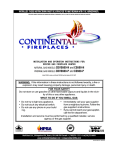
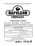
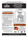
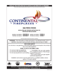
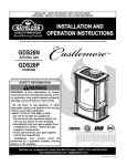
1
W415-0547 / B / 05.08.06
W415-0547 / B / 05.08.06
2
WARNINGS & SAFETY PRECAUTIONS
Do not store gasoline or other
flammable vapours and liquids in the
vicinity of this or any other appliance.
1.
2.
3.
Installation and service must be
performed by a qualified installer,
service agency or the gas supplier.
Follow the installation directions.
4.
5.
6.
WHAT TO DO IF YOU SMELL GAS
Do not try to light any appliance.
Do not use any phone in your building.
Immediately call your gas supplier
from a neighbor's phone. Follow the
gas supplier's instructions.
Do not touch any electrical switch.
If you cannot reach your gas supplier,
call the fire department.
If this fireplace is not properly
installed, a house fire may result.
W415-0547 / B / 05.08.06
3
TABLE of CONTENTS
2.
4.
5.
6.
7.
8.
9.
10.
11.
16.
17.
18.
19. Finishing
Glass door install and removal
Cast Front Installation and removal
20. Logo Placement
Log Placement
21. Optional Switch / Wiring Diagram
22. Lighting / Operation Instructions
23. Adjustments
Maintenance
Pilot Injector Replacement
Venturi Adjustment
Orifice Replacement
24. Replacements
Replacement Parts
Accessories
26. Trouble Shooting
28. Service History
Warnings and Safety Precautions
What to do if you smell gas
Warranty
General Instructions
General Information
Care of Glass and Plated Parts
Location and Clearances
Stove Dimensions
Clearances to Combustibles
Mantel or Shelf Clearances
Blower Installation
Terminal Installation
Venting
Venting Lengths and Air Terminal Locations
Typical and Special Vent Installations
Venting Termination
Wall and Ceiling Protection
Horizontal and Vertical Venting
Stove Vent Connection
Mobile Home Installation
Restricting Vertical Vents
Gas Installation
PLEASE RETAIN THIS MANUAL FOR FUTURE REFERENCE
WARNING
• The stove is a vented gas-fired heater. Do not burn wood or other materials in this stove.
• Adults and especially children should be alerted to the hazards of high surface temperatures and should
stay away to avoid burns or clothing ignition. Keep young children and animals away when the stove is
hot.
• Due to high temperatures, the stove should be located out of traffic and away from furniture and draperies.
• Clothing or other flammable material should not be placed on or near the stove.
• Any safety screen or guard removed for servicing must be replaced prior to operating the stove.
• It is imperative that the control compartments, burners and circulating blower and its passageway in the
stove and venting system are kept clean. The stove and its venting system should be inspected before use
and at least annually by a qualified service person. More frequent cleaning may be required due to excessive
lint from carpeting, bedding material, etc. The stove area must be kept clear and free from combustible
materials, gasoline and other flammable vapours and liquids.
• Under no circumstances should this stove be modified.
• This stove must not be connected to a chimney flue pipe serving a separate solid fuel burning appliance.
• Do not use this stove if any part has been under water. Immediately call a qualified service technician to
inspect the stove and to replace any part of the control system and any gas control which has been under
water.
• Do not operate the stove with the glass door opened, cracked or broken. Replacement of the glass should
be done by a licensed or qualified service person.
• Do not strike or slam shut the stove glass door.
NOTE: changes, other than editorial, are denoted by a vertical line in the margin.
W415-0547 / B / 05.08.06
4
NAPOLEON products are manufactured under the strict Standard of the world recognized
ISO 9001 : 2000 Quality Assurance Certificate.
NAPOLEON products are designed with superior components and materials, assembled by trained craftsmen who take great
pride in their work. The burner and valve assembly are leak and test-fired at a quality test station. The complete fireplace is
test-fired and thoroughly inspected by a qualified technician before packaging to ensure that you, the customer, receives the
quality product that you expect from NAPOLEON.
NAPOLEON GAS FIREPLACE PRESIDENT'S LIFETIME LIMITED WARRANTY
The following materials and workmanship in your new NAPOLEON gas fireplace are warranted against defects for as long as you
own the fireplace. This covers: combustion chamber, heat exchanger, stainless steel burner, phazer™ logs and embers, ceramic glass
(thermal breakage only), gold plated parts against tarnishing, porcelainized enamelled components and aluminium extrusion trims.
Electrical (110V and millivolt) components and wearable parts such as catalytic tiles, blowers, gas valves, thermal switch, switches,
wiring, remote controls, ignitor, gasketing, and pilot assembly are covered and NAPOLEON will provide replacement parts free of
charge during the first year of the limited warranty. Light bulbs are not covered by this warranty.
Labour related to warranty repair is covered free of charge during the first year. Repair work however, requires the prior approval
of an authorized company official. Labour costs to the accout of NAPOLEON are based on a predetermined rate schedule and any repair
work must be done through an authorized NAPOLEON dealer.
CONDITIONS AND LIMITATIONS
NAPOLEON warrants its products against manufacturing defects to the original purchaser only -- i.e., the individual or legal entity (registered customer) whose name appears on the warranty registration card filed with NAPOLEON -- provided that the purchase was made
through an authorized NAPOLEON dealer and is subject to the following conditions and limitations:
This factory warranty is nontransferable and may not be extended whatsoever by any of our representatives.
The gas fireplace must be installed by a licenced, authorized service technician or contractor. Installation must be done in accordance
with the installation instructions included with the product and all local and national building and fire codes.
This limited warranty does not cover damages caused by misuse, lack of maintenance, accident, alterations, abuse or neglect and parts
installed from other manufacturers will nullify this warranty.
This limited warranty further does not cover any scratches, dents, corrosion or discolouring caused by excessive heat, abrasive and
chemical cleaners nor chipping on porcelain enamel parts, mechanical breakage of PHAZER™ logs and embers, nor any venting components used in the installation of the fireplace.
NAPOLEON warrants its stainless steel burners against defects in workmanship and material for life, subject to the following conditions: During the first 10 years NAPOLEON will replace or repair the defective parts at our option free of charge. From 10 years to life,
NAPOLEON will provide replacement burners at 50% of the current retail price.
In the first year only, this warranty extends to the repair or replacement of warranted parts which are defective in material or workmanship
provided that the product has been operated in accordance with the operation instructions and under normal conditions.
After the first year, with respect to this President's Limited Lifetime Warranty, NAPOLEON may, at its discretion, fully discharge all obligations
with respect to this warranty by refunding to the original warranted purchaser the wholesale price of any warranted but defective part(s).
After the first year, NAPOLEON will not be responsible for installation, labour or any other costs or expenses related to the reinstallation
of a warranted part, and such expenses are not covered by this warranty.
Notwithstanding any provisions contained in this President's Limited Lifetime Warranty, NAPOLEON’S responsibility under this warranty
is defined as above and it shall not in any event extend to any incidental, consequential or indirect damages.
This warranty defines the obligations and liability of NAPOLEON with respect to the NAPOLEON gas fireplace and any other warranties
expressed or implied with respect to this product, its components or accessories are excluded.
NAPOLEON neither assumes, nor authorizes any third party to assume, on its behalf, any other liabilities with respect to the sale of this
product. NAPOLEON will not be responsible for: over-firing, downdrafts, spillage caused by environmental conditions such as rooftops,
buildings, nearby trees, hills, mountains, inadequate vents or ventilation, excessive venting configurations, insufficient makeup air, or
negative air pressures which may or may not be caused by mechanical systems such as exhaust fans, furnaces, clothes dryers, etc.
Any damages to fireplace, combustion chamber, heat exchanger, brass trim or other component due to water, weather damage, long
periods of dampness, condensation, damaging chemicals or cleaners will not be the responsibility of NAPOLEON.
The bill of sale or copy will be required together with a serial number and a model number when making any warranty claims from your
authorized dealer. The warranty registration card must be returned within fourteen days to register the warranty.
NAPOLEON reserves the right to have its representative inspect any product or part thereof prior to honouring any warranty claim.
ALL SPECIFICATIONS AND DESIGNS ARE SUBJECT TO CHANGE WITHOUT PRIOR NOTICE DUE TO ON-GOING PRODUCT IMPROVEMENTS. NAPOLEON® IS A REGISTERED
TRADEMARK OF WOLF STEEL LTD. PATENTS U.S. 5.303.693.801 - CAN. 2.073.411, 2.082.915. © WOLF STEEL LTD.
W415-0547 / B / 05.08.06
5
GENERAL INSTRUCTIONS
GENERAL INFORMATION
THIS GAS STOVE SHOULD BE INSTALLED AND SERVICED
BY A QUALIFIED INSTALLER to conform with local codes.
Installation practices vary from region to region and it is important to know the specifics that apply to your area,
for example: in Massachusetts State:
The blower power cord must be connected into a properly
grounded receptacle. The grounding prong must not be removed from the cord plug.
FOR YOUR SATISFACTION, THIS STOVE HAS BEEN TESTFIRED TO ASSURE ITS OPERATION AND QUALITY!
Minimum inlet gas supply pressure is 4.5 inches water column
for natural gas and 11 inches water column for propane. Maximum inlet gas pressure is 7 inches water column for natural
gas and 13 inches water column for propane. When the valve
is set to "HI", the manifold pressure under flow conditions is
3.5 inches water column for natural gas and 10 inches water
column for propane. When the fireplace is installed at elevations above 4,500ft, and in the absence of specific recommendations from the local authority having jurisdiction, the
certified high altitude input rating shall be reduced at the rate
of 4% for each additional 1,000ft.
Expansion / contraction noises during heating up and cooling
down cycles are normal and to be expected.
• The fireplace damper must be removed or welded in the open
position prior to installation of a fireplace insert or gas log.
• The appliance off valve must be a “T” handle gas cock.
• The flexible connector must not be longer than 36 inches.
• The appliance is not approved for installation in a bedroom or
bathroom unless the unit is a direct vent sealed combustion
product.
• WARNING: This product must be installed by a licensed plumber
or gas fitter when installed within the commonwealth of
Massachusetts.
In absence of local codes, install to the current CAN1-B149
Installation Code in Canada or to the National Fuel Gas
Code, ANSI Z223.1, and NFPA 54 in the United States. Mobile home installation must conform with local codes. In the
absence of local codes, install to the current standard for
gas equipped mobile housing CAN/CSA Z240 MH Series in
Canada or the manufactured home construction and safety
standard, Title 24 CFR, part 3280, or the Fire Safety Criteria
for manufactured home installations, Sites and Community
Standard ANSI/NFPA 501A in the United States.
Purge all gas lines with the glass door of the stove removed. Assure that a continuous gas flow is at the burner
before re-installing the door.
Under extreme vent configurations, allow several minutes (5-15) for the flame to stabilize after ignition.
It is recommended that all horizontal runs have a ¼ inch
rise per foot.
Objects placed in front of the stove must be kept a minimum of 48" away from the front face of the unit.
The stove and its individual shutoff valve must be disconnected
from the gas supply piping system during any pressure testing of that system at test pressures in excess of 1/2 psig (3.5
kPa). The stove must be isolated from the gas supply piping
system by closing its individual manual shutoff valve during
any pressure testing of the gas supply piping system at test
pressures equal to or less than ½ psig (3.5 kPa).
The stove, when installed with a blower, must be electrically
connected and grounded in accordance with local codes. In
the absence of local codes, use the current CSA C22.1 CANADIAN ELECTRICAL CODE in Canada or the ANSI/NFPA
70 NATIONAL ELECTRICAL CODE in the United States.
This appliance is only for use with the type of gas indicated
on the rating plate. This appliance is not convertible for use
with other gases, unless a certified kit is used.
CARE OF GLASS, AND PLATED PARTS
Do not use abrasive cleaners to clean these parts. Buff lightly
with a clean dry cloth.
The glass is 3/16" ceramic glass available from your Napoleon
/ Wolf Steel Ltd. dealer. DO NOT SUBSTITUTE MATERIALS.
Clean the glass after the first 10 hours of operation with a
recommended gas fireplace glass cleaner. Thereafter clean
as required. DO NOT CLEAN GLASS WHEN HOT! If the
glass is not kept clean permanent discolouration and / or
blemishes may result.
GDS25: Maximum input is 24,500 BTU/hr for natural gas.
Maximum output for natural gas is 19,600 BTU/hr at an efficiency of 80%. Maximum input is 23,000 BTU/hr for propane.
Maximum output for propane gas is 18,400 BTU/hr at an
efficiency of 80%.
This stove is approved for closet or recessed installations, as
well as for bathroom, bedroom and bed-sitting room installations and is suitable for mobile home installations. The natural
gas model can be installed in a mobile home that is permanently positioned on its site and fueled with natural gas.
W415-0547 / B / 05.08.06
6
LOCATION & CLEARANCES
Provide adequate accessibility clearance for
servicing and operating the stove.
Never obstruct the front opening of the stove.
*AT A DISTANCE OF 2" FROM THE WALL, INSTALLATION OR SERVICE
TO THE BLOWER MAY NOT BE PRACTICAL. A MINIMUM OF 5" WILL
BE REQUIRED IN ORDER TO INSTALL THE BLOWER.
As long as clearance to combustibles is kept within the required distances, the most desirable and beneficial location
for a Napoleon stove is in the centre of a building, thereby
allowing the most efficient use of the heat created. The location of windows, doors and the traffic flow in the room where
the stove is to be located should be considered. If possible,
you should choose a location where the vent will pass through
the house without cutting a floor or roof joist.
STOVE DIMENSIONS
FIGURE 1
17 1/2"
7" DIA.
25 5/8"
4" DIA.
23 5/8"
12 3/4"
23 1/2"
MAINTAIN THESE MINIMUM CLEARANCES
TO COMBUSTIBLES:
MANTEL OR SHELF CLEARANCES:
COMBUSTIBLE
MANTEL OR TRIM
MATERIAL
12”
MAX. MANTEL WIDTH
8”
MIN.
A. 4"
B. 2"*
C. 2"
FIGURE 2
STOVE SHOULD NOT BE INSTALLED DIRECTLY ON CARPETING.
MINIMUM
48" FROM STOVE TOP TO CEILING
TO CEILING FROM STOVE TOP.......................................48"
HORIZONTAL VENT
.....................................................1"
TOP............................................................................2"
VERTICAL VENT
ALL SIDES.............. .....................................................1"
SIDES AND BOTTOM
*AT A DISTANCE OF 2" FROM THE WALL, INSTALLATION OR SERVICE
TO THE BLOWER MAY NOT BE PRACTICAL. A MINIMUM OF 5" WILL
BE REQUIRED IN ORDER TO INSTALL THE BLOWER.
If less than 5" clearance is maintained between the back
of the stove and the back wall, it will be necessary to
disconnect the venting and gas pipe to move the stove
out for installation or service of the blower.
W415-0547 / B / 05.08.06
When the
fireplace is rear
vented, a mantel
or shelf may be
installed above
the GDS25 at a
minimum
distance of 8".
COMBUSTIBLE
MATERIALS
2”
7
BLOWER INSTALLATION
Blower (SEE LOCATION AND CLEARANCES)
1. Cut and remove the tie securing the blower switch wires
to the heat shield.
2. Connect the white wire coming from below the unit to the
terminal on the blower.
3. Connect the black blower wire to the black wire coming
from below the unit.
4. Insert the clips on the blower housing into the cutouts in the
rear shield. Push down to lock the clips into position.
5. Secure the blower using the screw and lock washer supplied.
Note: Ensure that all the wires are tucked into the blower
switch housing.
7
7
8
3
7
3
2
5
Switches
6. Open the switch housing by removing the top screw.
7. Install the thermodisc bracket as shown, using 2 of the
screws supplied. Connect the flagged leads to the terminals
of the thermodisc.
Remove the knock out from the housing label.
8. Install the variable speed switch (rheostat) into the housing
with the wires facing up. Secure the switch to the housing
using the pal nut and the knob supplied.
9. Connect the male connector on the switch to the female
connector coming from the unit.
10. Tuck all of the wires into the housing and close. Secure
using the screw removed in step 6.
9
4
1
4
4
1
7
9
4
2
5
8
ACCENT LITE REPLACEMENT
Your Bayfield comes equipped with our “Accent Lite”.
If in the event the lamp or lens needs to be replaced,
follow these instructions.
Disconnect the two wire leads at the wire nut. Remove
the four screws securing the accent lite assembly from
the relief door. Disassemble the lite and the lamp now
can be accessed
SHEILD
Note: Do not handle the lamp (bulb) with bare
fingers, protect with a clean dry cloth.
The lamp will pull straight out of the socket. Replace with
Wolf Steel parts only, as lamp and lens are special “high
temperature” products.
When re-installing, ensure integrity of gasket seal.
THE FIREBOX
MUST BE SEALED.
WIRE NUT
COVER PLATE
GASKET
GLASS LENS
RAIL
GASKET
RELIEF
DOOR
RAIL
When re-assembling
the light assembly,
care must be taken
with all gaskets.
“Light Leakage”
from above the
cast doors may be
noticed. The holes
in the lamp housing
are necessary for
ventilation and must
not be covered.
W415-0547 / B / 05.08.06
8
AIR TERMINAL LOCATIONS
INSTALLATIONS
CANADIAN
U.S.A.
A
12 INCHES
12 INCHES
Clearance above grade, veranda porch, deck or balcony.
B
12 INCHES
9 INCHES
Clearance to windows or doors that open.
C
12 INCHES*
12 INCHES*
Clearance to permanently closed windows.
D
18 INCHES**
18 INCHES**
Vertical clearance to ventilated soffit located above the terminal within
a horizontal distance of 2 feet from the centerline of the terminal.
E
12 INCHES**
12 INCHES**
Clearance to unventilated soffit.
F
0 INCHES
0 INCHES
0 INCHES***
0 INCHES***
Clearance to an inside non-combustible corner wall or protruding
non-combustible obstructions (chimney, etc.).
2 INCHES***
2 INCHES***
Clearance to an inside combustible corner wall or protruding combustible obstructions ( vent chase, etc.).
H
3 FEET
3 FEET****
Clearance to each side of the centerline extended above the meter
/ regulator assembly to a maximum vertical distance of 15ft.
I
3 FEET
3 FEET****
Clearance to a service regulator vent outlet.
J
12 INCHES
9 INCHES
Clearance to a non-mechanical air supply inlet to the building or a
combustion air inlet to any other appliance.
K
6 FEET
3 FEET†
L
7 FEET‡
7 FEET****
M
12 INCHES††
12 INCHES****
N
16 INCHES
16 INCHES
O
2 FEET†*
2 FEET†*
G
*
**
***
****
†
‡
††
†*
Clearance to an outside corner wall.
Clearance to a mechanical air supply inlet.
Clearance above a paved sidewalk or paved driveway located on
public property unless fitted with a heat shield kit GD-301.
Clearance under a veranda, porch, deck or balcony.
Clearance above the roof.
Clearance from an adjacent wall including neighbouring buildings.
Recommended to prevent condensation on windows and thermal breakage
It is recommended to use a heat shield and to maximize the distance to vinyl clad soffits.
The periscope GD-201 requires a minimum 18 inches clearance from an inside corner.
This is a recommended distance. For additional requirements check local codes.
Three feet above if within 10 feet horizontally.
A vent shall not terminate directly above a sidewalk or paved driveway that is located between two single family
dwellings and serves both dwellings.
Permitted only if the veranda, porch, or deck is fully open on a minimum of two sides beneath the floor.
Recommenced to prevent recirculation of exhaust products. For additional requirements check local codes.
W415-0547 / B / 05.08.06
9
VENTING
VENTING LENGTHS &
AIR TERMINAL LOCATIONS
Use only Wolf Steel, Simpson Dura-Vent, Selkirk Direct Temp
or American Metal Amerivent venting components.
For Simpson Dura-Vent, Selkirk Direct Temp and American
Metal Amerivent, follow the installation procedure provided
with the venting components.
All outer pipe joints of these venting systems must be sealed
using Red RTV High Temperature Sealant.
Wolf Steel, Simpson Dura-Vent, Selkirk Direct Temp and
American Metal Amerivent venting systems must not be
combined.
A starter adaptor must be used and may be purchased from
the corresponding supplier:
PART
SUPPLIER
Duravent - GDS924N
Wolf Steel
Amerivent - 4DSCB-N1
American Metal
Direct Temp - 4DT-AAN
Selkirk
For vent systems that provide seals on the inner exhaust flue,
only the outer air intake joints must be sealed using a red high
temperature silicone (RTV). This same sealant maybe used
on both the inner exhaust and outer intake vent pipe joints
of all other approved vent systems except for the exhaust
vent pipe connection to the fireplace flue collar which must
be sealed using the black high temperature sealant Mill Pac.
High temperature sealant must be ordered separately.
When using Wolf Steel venting components, use only the
following vent kits: WALL TERMINAL KIT GD175 (7-1/2'
of venting included), WALL TERMINAL KIT GD176 (24" of
venting included), or 1/12 TO 7/12 PITCH ROOF TERMINAL
KIT GD110, 8/12 TO 12/12 ROOF TERMINAL KIT GD111,
FLAT ROOF TERMINAL KIT GD112 or STOVE PERISCOPE
KIT GD180 (for wall penetration below grade) in conjunction
with the appropriate venting components.
For optimum performance, it is recommended that all horizontal runs have a
minimum ¼ inch rise per foot.
• These vent kits allow for
either horizontal or vertical
16 INCHES
venting of the stove.
• The maximum number of
4" flexible connections
40 FEET
is 3 horizontally or three
MAXIMUM
vertically (excluding the
3 FEET
stove and the air terminal
MINIMUM
connections).
• When terminating
vertically, the minimum
vertical rise is 3 feet
FIGURE 4
above the stove and the
maximum vertical rise is
40 feet. FIGURE 4.
Deviation from the minimum vertical vent length can
create difficulty in burner start-up and/or carboning.
Use an adjustable pipe as the final length of rigid
piping to the stove for ease of installation.
• For optimum flame appearance and stove performance,
keep the vent length and number of elbows to a mini
mum.
• The air terminal must remain unobstructed at all times.
Examine the air terminal at least once a year to verify
that it is unobstructed and undamaged.
The maximum horizontal run with a 57 inch vertical rise immediately above the stove is 20 feet . FIGURES 6a-b.
FIGURE 5
HORIZONTAL RUN NOT TO
EXCEED VERTICAL RISE
FIGS 6a-b
TYPICAL CORNER INSTALL
WITH ZERO RISE
24” MAX
W415-0547 / B / 05.08.06
10
TYPICAL VENT INSTALLATIONS
NOTE:
When terminating vertically above 15', the
restrictor plate must be in the fully closed position. Refer to Restricting Vertical Vents.
16"
FIGURES 3 a-c
40FT
MAX
3FT
MIN
SPECIAL VENT INSTALLATIONS
PERISCOPE TERMINATION
Use the GD201 periscope kit to locate the air termination
above grade. The periscope must be installed so that when
final grading is completed, the bottom air slot is located a
minimum of 12 inches above grade. The maximum allowable
vent length depends on the fireplace, as illustrated.
12"MINIMUM
24" MINIMUM
REGARDLESS
OF HORIZONTAL
VENT LENGTH
BELOW GRADE INSTALLATION
MAXIMUM 10FT VENT LENGTH
USE GD201 PERISCOPE KIT
W415-0547 / B / 05.08.06
FIGURE 4
11
DEFINITIONS
ELBOW VENT LENGTH VALUES
for the following symbols used in the venting calculations
and examples are:
> - greater than
> - equal to or greater than
< - less than
< - equal to or less than
HT - total of both horizontal vent lengths (HR) and offsets
(HO) in feet
HR - combined horizontal vent lengths in feet
HO - offset factor: .03(total degrees of offset - 135°*) in
feet
VT - combined vertical vent lengths in feet
feet
0.03
0.45
0.9
1.35
2.7
1°
15°
30°
45°*
90°*
inches
0.5
6.0
11.0
16.0
32.0
* the first 45º and 90° offset has a zero value and is
shown in the formula as -45° and -90º respectively or
-135º when combined.
HORIZONTAL TERMINATION
when (HT) < (VT)
For vent configurations requiring more than one 45º and 90°
elbow, the following formulas apply:
Formula 1: HT < VT
Formula 2: HT + VT < 40 feet
90°
Example 1:
H2
90°
FIGURE 5
V1
FIGURE 6
45º
45º
H1
90°
Simple venting configuration (only one 45º and 90° elbow)
39
40
30
REQUIRED
VERTICAL
RISE IN
FEET (VT)
20
10
0
2.5
5
7.5
10
12.5
15
17.5
20
CALCULATED HORIZONTAL VENT RUN
PLUS OFFSETS IN FEET (HT)
The shaded area within the lines represents acceptable
values for HT and VT .
V1 = 8 ft
VT = V1 = 8 ft
H1 = 2.5 ft
H2 = 2 ft
HR = H1 + H2 = 2.5 + 2 = 4.5 ft
HO = .03(one 45º elbow + two 90º elbows - 135º)
=0.3(225-135º) = 2.7ft
HT = HR + HO = 4.5 + 2.7 = 7.2 ft
HT + VT = 7.2 +8 =15.2ft
Formula 1:
Formula 2:
HT < VT
7.2 < 8
HT + VT < 40 feet
15.2 < 40
Since both formulas are met, this vent configuration is
acceptable.
W415-0547 / B / 05.08.06
12
HORIZONTAL TERMINATION
when (HT) > (VT)
Simple venting configuration (only one 45º and 90° elbow)
Example 2:
H1
FIGURE 8
See graph to determine
the required vertical rise VT
for the required horizontal
run HT.
45°
FIGURE 7
V1
90°
90°
90°
H3
H2
V2
H4
150
V1
V2
VT
H1
H2
H3
H4
HR
HO
140
REQUIRED
VERTICAL
RISE IN
INCHES (VT)
= 4 ft
= 1.5 ft
= V1 + V2 = 4 ft + 1.5 ft = 5.5 ft
= 2 ft
= 1 ft
= 1 ft
= 1.5 ft
= H1 + H2 + H3 + H4 = 2 + 1 + 1 + 1. 5 = 5.5 ft
= .03(one 45º elbow + three 90º elbow -135º)
=.03(315-135)=5.4ft
= HR + HO = 5.5 +5.4 = 10.9 ft
HT
HT + VT = 10.9 + 5.5 = 16.4 ft
130
120
110
100
90
80
70
60
50
40
Formula 1: HT < 4.2 VT
4.2 VT = 4.2 x 5.5 = 23.1 ft
30
20
10.9 < 16.8
10
0
5
10
15
20
Formula 2: HT + VT < 24.75 feet
16.4 < 24.75
HORIZONTAL VENT RUN PLUS OFFSETS IN FEET
The shaded area within the lines represents acceptable
values for HT and VT .
For vent configurations requiring more than one 45º and 90°
elbow the following formulas apply:
Formula 1: HT < 4.2 VT
Formula 2: HT + VT < 24.75 feet
W415-0547 / B / 05.08.06
Since both formulas are met, this vent configuration is
acceptable.
13
VERTICAL TERMINATION
when (HT) < (VT)
V2
See graph to determine the required vertical rise VT for the V
T
= 10 ft
= V1 + V2 = 5 + 10 = 15 ft
V2
FIGURE 9
FIGURE10
90°
H2
90°
V1
45°
45°
H1
90°
required horizontal run HT.
For vent configurations requiring more than one 45º and one
150
H1
H2
HR
HO
= 3 ft
= 2.5 ft
= H1 + H2 = 3 + 2.5 = 5.5 ft
= .03(one 45º elbow + three 90º elbows - 135º)
= .03(45+90+90+90-135)=5.4
HT
= HR + HO = 5.5 + 5.4 = 10.9 ft
HT + VT = 10.9 + 15 = 25.9 ft
140
130
120
110
100
90
REQUIRED VERTICAL RISE
IN FEET (VT)
80
70
60
HT < V T
10.9 < 15
Formula 2: HT + VT < 40 feet
25.9 < 40
Since both formulas are met, this vent configuration is
acceptable.
Formula 1:
50
40
30
20
10
0
5
10
15
20
HORIZONTAL VENT RUN
PLUS OFFSETS IN FEET
The shaded area within the lines represents acceptable
values for HT and VT.
90° elbow , the following formulas apply:
Formula 1: HT < VT
Formula 2: HT + VT < 40 feet
Example 3:
V1
= 5 ft
W415-0547 / B / 05.08.06
14
VERTICAL TERMINATION
when (HT) > (VT)
Simple venting configurations
See graph to determine the required vertical rise VT for the
FIGURE 11
HT + VT < 40 feet
15.9 < 40
Since only formula 2 is met, this vent configuration
is unacceptable and a new fireplace location or vent
configuration will need to be established to satisfy both
formulas.
Formula 2:
Example 5:
V2
90°
required horizontal run HT.
For vent configurations requiring more than one 45º and one
90° elbow , the following formulas apply:
19
REQUIRED
VERTICAL
RISE IN
FEET (VT)
45°
H1
20
H2
V1 45°
90°
10
H3
90°
FIGURE 13
3
0
5
10
15
25
20
30
HORIZONTAL VENT RUN PLUS OFFSET IN FEET
The shaded area within the lines represents acceptable
values for HT and VT.
Formula 1: HT < 3VT
Formula 2: HT + VT < 40 feet
Example 4:
V1
= 1 ft
FIGURE 12
V1
V2
VT
H1
H2
H3
HR
HO
= 1.5 ft
= 8 ft
= V1 + V2 = 1.5 + 8= 9.5 ft
= 1 ft
= 1 ft
= 10.75 ft
= H1 + H2 + H3 = 1 + 1 + 10.75 = 12.75 ft
= .03(three 90° elbows + two 45° elbow - 135°)
= .03(90 + 90 + 90 + 45 + 45 - 135) = 6.75 ft
HT
= HR + HO = 12.75 + 6.75 = 19.5 ft
HT + VT = 19.5 + 4.5= 29 ft
HT < 3VT
3VT = 3 x 9.5 = 28.5 ft
19.5 < 28.5
Formula 2: HT + VT < 40 feet
29 < 40
Since both formulas are met, this vent configuration is
acceptable.
Formula 1:
45°
90°
H1
V2
V1
H2
90°
90°
V2
VT
H1
H2
HR
HO
= 1.5 ft
= V1 + V2 = 1 + 1.5 = 2.5 ft
= 6 ft
= 2 ft
= H1 + H2 = 6 + 2 = 8 ft
= .03(one 45º elbow + three 90º elbow - 135º)
= .03(45 + 90 + 90 + 90 - 135) = 5.4 ft
HT
= HR + HO = 8 + 5.4 = 13.4 ft
HT + VT = 13.4 + 2.5 = 15.9 ft
HT < 3VT
3VT = 3 x 2.5 = 7.5 ft
13.4 > 7.5
Since this formula is not met, this vent configuration is
unacceptable.
Formula 1:
W415-0547 / B / 05.08.06
15
VERTICAL THROUGH EXISTING CHIMNEY
INSTALLATION
This appliance is designed to be attached to a 3" co-linear aluminum flex vent system running the full length of a
masonry chimney.
The flexliner accommdates any contours of a masonry
chimney, however, it is necessary to keep the flexible liner
as straight as possible. The inlet air collar of the termination cap must be connected to the air intake pipe.
Use Simpson Duravent Chimney Liner Termination Kit
- 923GK (Baseplate and Co-Linear to Co-Axial Adaptor.
Follow manufacturers (Simpson Dura-Vent) installation
instructions.
When installing the unit to this system, Duravent vent
components must be used. You must start with a Duravent
adaptor, GDS924N, directly off the unit. The GDS924N is
only available at your Napoleon dealer.
W415-0547 / B / 05.08.06
16
WALL AND CEILING PROTECTION
FIGURE 16
VERTICAL INSTALLATION
This application occurs
when venting through a
roof.
Installation kits for various roof pitches are
available from your Napoleon dealer. See Accessories to order the
specific kit required.
FIGURE 17
10"
9"
FIRESTOP
UNDERSIDE OF JOIST
1. Determine the air terminal location and move the stove into
position. Cut and frame 9" x 10" openings in the ceiling and
the roof to provide the minimum 1 inch clearance between
the stove pipe and any combustible material. Try to center the
exhaust pipe location midway between two joist to prevent
having to cut them. Use a plumb bob to line up the center of
the openings.
DO NOT FILL THIS SPACE WITH ANY TYPE OF MATERIAL.
HORIZONTAL INSTALLATION
This application occurs when venting through an exterior wall.
Having determined the air terminal location, cut and frame
a hole in an exterior wall with a minimum rectangle opening
of 10" x 9".
IMPORTANT: FOR OPTIMUM PERFORMANCE, THE
STOVE PIPE SHOULD RISE ¼" PER FOOT OF RUN.
1. Assemble the shield to the spacer as shown, using the
3 shorter screws supplied.
The shield is meant to protect combustible materials within
the wall. If the shield is deeper than the combustible portion
of the wall, cut to fit.
2. Apply a bead of caulking all around and place the firestop
spacer over the framework to restrict cold air from being drawn
into the room or around the stove. Ensure that both spacer
and shield maintain the required clearance to combustibles.
Secure the spacer in place using the 4 longer screws supplied. Once the vent pipe is installed in its final position, apply
sealant between the pipe and the firestop spacer.
W415-0547 / B / 05.08.06
A vent pipe shield will
prevent any materials
FIGURE 18
such as insulation, from
CAULKING filling up the 1" air space
VENT PIPE
around the pipe. Nail
SHIELD
headers between the
joist for extra support.
2. Apply a bead of caulking (not supplied) to the framework
or to the Wolf Steel vent pipe shield plate or equivalent (in
the case of a finished ceiling), and secure over the opening in the ceiling. A firestop must be placed on the bottom
of each framed opening in a roof or ceiling that the venting
system passes through. Apply a bead of caulking all around
and place a firestop spacer over the vent shield to restrict
cold air from being drawn into the room or around the stove.
Ensure that both spacer and shield maintain the required
clearance to combustibles. Once the vent pipe is installed
in its final position, apply sealant between the pipe and the
firestop spacer.
3. In the attic, after the pipe
has been installed, slide the
VENT
vent pipe collar down to cover
PIPE
up the open end of the shield
COLLAR
O
and tighten. This will prevent any
VENT PIPE
materials, such as insulation,
SHIELD
from filling up the 1" air space
around the pipe.
FIGURE 19
17
HORIZONTAL VENTING INSTALLATION
VERTICAL VENTING INSTALLATION
FOR SAFE AND PROPER OPERATION OF THE STOVE,
FOLLOW THE VENTING INSTRUCTIONS EXACTLY.
1. Fasten the roof support
to the roof using the screws
provided. The roof support
is optional. In this case the
venting is to be adequately
supported using either an
alternate method suitable to
ROOF SUPPORT
the authority having jurisdiction
or the optional roof support.
2. Stretch the inner aluminum flex
INNER
liner to the required length. Slip the
SLEEVE
liner a minimum of 2” over the inner
sleeve of the air terminal connector
and secure with 3 #8 screws. Seal
AIR
TERMINAL
using a heavy bead of the high
CONNECTOR
temperature sealant.
3.Repeat using the outer aluminum
HIGH
TEMPERATURE
flex liner.
SEALANT
INNER FLEX
4. Thread the air terminal connector
LINER
/ liner assembly down through
OUTER FLEX
LINER
the roof. The air terminal must be
located vertically and plumb. Attach DO NOT CLAMP
the air terminal connector to the roof THE FLEXIBLE
support, ensuring that the top of the
ALUMINIUM
LINER.
air terminal is 16” above the highest
point that it penetrates the roof.
5. Remove nails from the shingles, above and to the
sides of the chimney. Place the
flashing over the air terminal
connector leaving a min. 3/4”
of the air terminal connector
AIR INLET
showing above the top of the
BASE
flashing. Slide the flashing
underneath the sides and upper
CAULKING
edge of the shingles. Ensure
STORM COLLAR
that the air terminal connector
is properly centred within the
WEATHER
SEALANT
flashing, giving a 3/4” margin
all around. Fasten to the roof.
Do not nail through the lower
FLASHING
portion of the flashing. Make
Spacers are attached to
weather-tight by sealing with
the inner flex liner at
caulking. Where possible, cover predetermined intervals to
the sides and top edges of the maintain a 1-1/4” air gap to
flashing with roofing material.
the outer flex liner. These
6. Aligning the seams of
spacers must not be
the terminal and air terminal
removed.
connector, place the terminal
over the air terminal connector
making sure the liner goes into the hole in the terminal.
Secure with the three screws provided.
7. Apply a heavy bead of weatherproof caulking 2
inches above the flashing. Note: Maintain a minimum
2” space between the air inlet base and the storm collar.
Install the storm collar around the air terminal and slide
down to the caulking. Tighten to ensure that a weathertight seal between the air terminal and the collar is
achieved.
ALL HORIZONTAL VENT RUNS MAY HAVE A 0" RISE
PER FOOT.
FOR OPTIMUM PERFORMANCE IT IS RECOMMENDED
THAT ALL HORIZONTAL RUNS HAVE A MINIMUM
¼ INCH RISE PER FOOT.
ALL INNER EXHAUST AND OUTER INTAKE VENT
PIPE JOINTS MAY BE SEALED USING EITHER RED
RTV HIGH TEMP SILICONE SEALANT OR BLACK
HIGH TEMP MILL PAC WITH THE EXCEPTION OF THE
FIREPLACE EXHAUST FLUE COLLAR WHICH MUST BE
SEALED USING MILL PAC (NOT SUPPLIED).
1. Stretch the 4" diameter aluminium flexible liner to the required length taking into account the additional length needed
for the finished wall surface.
Spacers are attached to the 4" inner flex liner at predetermined
intervals to maintain a 1-1/4" air gap to the 7" outer stove pipe.
These spacers must not be removed.
Slip a 4" diameter length of aluminium flexible liner a minimum
of 2" over the inner sleeve of the air terminal. Secure to the
sleeve using 3 screws. Seal the joint and screw heads using
the high temperature sealant.
2. Slip the first section of 7" diameter stove pipe a minimum
of 2" over the outer sleeve of the air terminal. Secure to the
sleeve using 3 screws. Seal the joint and screw heads using
high temperature sealant.
3. Insert the liners through the firestop / vent pipe shield.
Holding the air terminal (lettering in an upright, readable
position), secure to the exterior wall. Make weather tight by
sealing with caulking (not supplied). The air terminal mounting
plate may be recessed (up to 1½" maximum) into the exterior
wall or siding.
4. If more than one length of liner needs to be used to reach
the stove, couple them together as illustrated in FIGURE 21.
Seal the joints using the same procedure as described
above.
The vent system must be supported approximately every
10 feet along a horizontal run. Use supports or equivalent
non-combustible strapping to maintain the 1" clearance from
combustibles.
#
#10x2"
CAULKING
4"FLEX
FIGURE 20
AT
TE
NT
CA
IO
UT
N-
IO
N
CH
-
AU
D
HO
T
7" RIGID
PIPE
HI-TEMP
SEALANT
#8x1/2"
SELF DRILLING
SCREWS &
WASHERS
HI-TEMP
SEALANT
4"COUPLER
FIGURE 21
7" RIGID PIPE
7" RIGID PIPE
4"FLEX
PIPE
2”
W415-0547 / B / 05.08.06
18
STOVE VENT CONNECTION
1. Attach the adjustable pipe to the last section of rigid piping. Secure with screws and seal.
2. Install the 4" aluminium flexible liner
#8x1/2"
SELF DRILLING
SCREWS
to the stove. Secure with 3 screws 2" OVERLAP
and flat washers. Seal the joint
HI-TEMP
SEALANT
and screw holes using high
temperature sealant.
3. Run a bead of high temperature sealant Mill Pac
around the inside of the air
intake collar. Pull the adjustable pipe a minimum 2" into
the air intake collar.
ENSURE THAT THE SEALANT IS NOT VISIBLE ON THE EXTERIOR PIPES ONCE
INSTALLATION IS COMPLETED. AN OPTIONAL DECORATIVE BRASS BAND IS AVAILABLE FOR THIS USE.
(STANDARD WITH A GD175 KIT AND GD-176). IN THE
EVENT THAT THE VENTING MUST BE DISASSEMBLED,
CARE MUST BE TAKEN TO RESEAL THE VENTING.
MOBILE HOME INSTALLATION
In Canada, mobile home installation may be vented horizontally or vertically. In the United States, it may only be installed
vertically. See "Vertical Venting" or "Horizontal Air Terminal
Installation" for installation.
For mobile home installations, the fireplace must be fastened
in place. It is recommended that the fireplace be secured in
all installations. Use the levelling/securing kit, GDSLL-KT for
this purpose.
RESTRICTING VERTICAL VENTS
FIGURE 27
RESTRICTOR
SHOWN IN A FULLY
OPEN POSITION
Vertical installations may display a very active flame. Loosen
the two screws and slide the restrictor plate blocking the exhaust path. This reduces the velocity of the exhaust gases,
slowing down the flame pattern and creating a more traditional
flame appearance. For vertical vents greater than 15 feet, this
restrictor must be fully closed.
W415-0547 / B / 05.08.06
RESTRICTOR
SHOWN IN A FULLY
CLOSED POSITION
GAS INSTALLATION
1. Install rigid black pipe, or 1/2" type L copper tubing with a
shut-off valve to the stove.
2. Seal and tighten the gas line securely to a flex connector.
3/8NPT
FLEXIBLE
SHUT OFF
CONNECTOR
FIGURE 28
ADAPTER
FITTING
VALVE
1/2FPT
BLACK
PIPE
DO NOT KINK FLEXIBLE CONNECTOR.
3. Check for gas leaks by brushing on a soap and water solution. DO NOT USE OPEN FLAME.
19
FINISHING
GLASS DOOR INSTALLATION
AND REMOVAL
1. Lift the top cast piece off of the unit.
2. Detach the front cast piece from the side pieces by removing the screws from the brackets located in the upper
inside corners.
3. Slide the front straight up to remove.
CAST FRONT INSTALLATION
AND REMOVAL
1. Lift the top cast piece off of the unit.
2. Unlatch the door latches from the door.
3. Slide the door straight up to remove.
3
3
BRACKET
2
DOOR
LATCHES
FIGURE 30
SWITCH FUNCTIONS
MAIN
BURNER
SWITCH
FAN
CONTROL
2
SCREWS
ACCENT
LIGHT
SWITCH
FRONT
FIGURE 31
Follow the above steps in reverse in order to reinstall
the door. Ensure that the bottom of the door meets the
door retainer before closing the latches.
Follow the above steps in reverse in order to reinstall
the cast front. Ensure that the tabs on the underside of
the front fit behind the front legs.
Note: It is not necessary to remove the cast front, in order
to remove the door.
FIGURE 32
FRONT
TAB
DOOR
RETAINER
FRONT
LEGS
W415-0547 / B / 05.08.06
20
LOGO PLACEMENT
1.27cm
Remove the backing from the the logo and position onto the
control door as shown.
1.27cm
LOGO
LOG PLACEMENT
It is not necessary to remove the cast front, however, this
will make for a more simple log installation.
In order to assemble the log set, the door must be removed,
see Cast Front / Glass Door Removal in the FINISHING
section of this manual.
FIGURE 33a-d
LOG LOCATING SCREWS
2. Place the hole in the underside of log #2 onto the locating
screw, on the left side of the burner. The fibre burner is formed
to cradle the centre of the log.
BRACKET
1. Place the rear log, as shown, onto the rear log support
brackets. Ensure the cutout on the left underside of the log,
fits over the pilot assembly. Bend the bracket on the right side
to help retain the rear log.
W415-0547 / B / 05.08.06
3. Place the hole in the underside of log #3 onto the locating
screw, on the right side of the burner. The bottom branch of
log #3 sits infront of, and against, the right end of log #2.
4. Reinstall the glass door & front.
21
OPTIONAL SWITCH / WIRING DIAGRAM
The on/off switch is located on the back of the
GDS25 at the top right corner. For ease of accessibility, an optional remote wall switch or millivolt
thermostat may be installed in a convenient location.
The recommended maximum lead length depends on
wire size:
WIRE SIZE
MAX. LENGTH
14 gauge
100 feet
16 gauge
60 feet
18 gauge
40 feet
Route 2-strand (solid core) wire through the electrical hole located at the bottom left side of the unit.
Connect the wires from the wall switch / thermostat
to the two brown wires extending from the fireplace
mounted ignition control box.
Purge all gas lines with the glass door of the fireplace open.
Assure that a continuous gas flow is at the burner before closing the door.
IGNITION
MODULE
PILOT
ASSEMBLY
NOTE: WIRE TAGS
Yellow [through
Gas line
(S)
conduit]
ARE BRACKETED
Orange [through
(I) independent
conduit]
BATTERY
HOLDER
Black
PILOT
GAS LINE
BURNER
SWITCH / WALL
THERMOSTAT
GAS VALVE
Red
BATTERY
RELAY
AC ADAPTOR
WIRE
HARNESS
Red (3 Volt)
Black (12 Volt)
To Accent Light &
Accent Light Switch
Black
(-)
MODULE
PLUG
Black
(TP)
Orange
Black
Brown
(SWI)
Orange x2
(THTP)
Green
Green x2
(TH)
Yellow
Red
(+)
Black
Blue
RELAY
PLUG
W415-0547 / B / 05.08.06
22
Purge all gas lines with the glass door removed. Assure that a continuous gas flow is at the burner before reinstalling the
door.
FOR YOUR SAFETY READ BEFORE OPERATING
WARNING: IF YOU DO NOT FOLLOW THESE INSTRUCTIONS EXACTLY, A FIRE OR EXPLOSION
MAY RESULT CAUSING PROPERTY DAMAGE, PERSONAL INJURY OR LOSS OF LIFE.
A. THIS FIREPLACE IS EQUIPPED WITH AN IGNITION DEVICE
WHICH AUTOMATICALLY LIGHTS THE PILOT. DO NOT TRY
TO LIGHT BY HAND.
B. BEFORE OPERATING SMELL ALL AROUND THE FIREPLACE
AREA FOR GAS AND NEXT TO THE FLOOR BECAUSE SOME
GAS IS HEAVIER THAN AIR AND WILL SETTLE ON THE
FLOOR.
C. USE ONLY YOUR HAND TO TURN THE GAS CONTROL
KNOB. NEVER USE TOOLS. IF THE KNOB WILL NOT TURN
BY HAND, DO NOT TRY TO REPAIR IT. CALL A QUALIFIED
SERVICE TECHNICIAN. FORCE OR ATTEMPTED REPAIR
MAY RESULT IN A FIRE OR EXPLOSION.
D. DO NOT USE THIS FIREPLACE IF ANY PART HAS BEEN
UNDER WATER. IMMEDIATELY CALL A QUALIFIED SERVICE
TECHNICIAN TO INSPECT THE FIREPLACE AND
REPLACE ANY PART OF THE CONTROL SYSTEM AND
ANY GAS CONTROL WHICH HAS BEEN UNDER
WATER.
WHAT TO DO IF YOU SMELL GAS:
• TURN OFF ALL GAS TO THE FIREPLACE.
• OPEN WINDOWS.
• DO NOT TRY TO LIGHT ANY APPLIANCE.
• DO NOT TOUCH ANY ELECTRIC SWITCH; DO NOT
USE ANY PHONE IN YOUR BUILDING.
• IMMEDIATELY CALL YOUR GAS SUPPLIER FROM A
NEIGHBOUR'S PHONE FOLLOW THE GAS SUPPLI
ER'S INSTRUCTIONS.
• IF YOU CANNOT REACH YOUR GAS SUPPLIER, CALL
THE FIRE DEPARTMENT.
OPERATING INSTRUCTIONS
1. STOP! READ THE ABOVE SAFETY INFORMATION ON
THIS LABEL.
2. TURN REMOTE WALL SWITCH TO OFF POSITION.
3. TURN OFF ALL ELECTRIC POWER TO THE FIREPLACE
AND REMOVE BATTERIES.
4. THIS FIREPLACE IS EQUIPPED WITH AN IGNITION
DEVICE WHICH AUTOMATICALLY LIGHTS THE PILOT. DO
NOT TRY TO LIGHT THE PILOT BY HAND.
5. TURN MANUAL SHUTOFF VALVE CLOCKWISE
TO
OFF.
6. OPEN THE GLASS DOOR.
7. WAIT FIVE (5) MINUTES TO CLEAR OUT ANY GAS. IF
YOU SMELL GAS INCLUDING NEAR THE FLOOR, STOP!
FOLLOW "B" IN THE ABOVE SAFETY INFORMATION ON
THIS LABEL. IF YOU DON'T SMELL GAS GO TO THE
NEXT STEP.
8. CLOSE THE GLASS DOOR.
9. TURN MANUAL SHUTOFF VALVE COUNTERCLOCKWISE
TO ON.
10. TURN ON ALL ELECTRIC POWER TO THE FIREPLACE
AND RE-INSTALL BATTERIES.
11. TURN ON REMOTE WALL SWITCH TO ON POSITION.
12. IF FIREPLACE WILL NOT OPERATE, FOLLOW
INSTRUCTIONS "TO TURN OFF GAS" AND CALL YOUR
SERVICE TECHNICIAN OR GAS SUPPLIER.
TO TURN OFF GAS
1. TURN OFF REMOTE WALL SWITCH TO THE FIREPLACE.
2. TURN OFF ALL ELECTRICAL POWER TO THE FIREPLACE IF SERVICE IS TO BE PERFORMED.
3. TURN MANUAL SHUTOFF VALVE CLOCKWISE
TO OFF. DO NOT FORCE.
W415-0547 / B / 05.08.06
23
MAINTENANCE
ing or brushing, at least once a year.
TURN OFF THE GAS AND UNPLUG
3. Check to see that all burner ports are burning. Clean out
ELECTRICAL POWER BEFORE
any of the ports which may not be burning or are not burning
SERVICING THE STOVE!
properly.
CAUTION: Label all wires prior to disconnection when servicing controls. Wiring errors can cause improper and dangerous
operation. Verify proper operation after servicing. This stove
and its venting system should be inspected before use and
at least annually by a qualified service person. The fireplace
area must be kept clear and free of combustible materials,
gasoline or other flammable vapours and liquids. The flow of
combustion and ventilation air must not be obstructed.
1. In order to properly clean the burner and pilot assembly,
remove the logs exposing both assemblies.
2. Keep the control compartment, logs, burner, air shutter
opening and the area surrounding the logs clean by vacuum-
4. Check to see that the pilot flames are large enough to
engulf the thermocouple and the thermopile on one leg and
reaches toward the burner on the other leg.
5. Replace the cleaned logs.
6. Check to see that the main burner ignites completely on
all openings when the gas knob for the burner is turned on.
A 5-10 second total light-up period is satisfactory. If ignition
takes longer, consult your Napoleon dealer/distributor.
7. Check that the door gasketing is not broken or missing.
ADJUSTMENTS
PILOT INJECTOR AND ORIFICE REPLACEMENT
1. Turn off the electrical
and gas supply to the fireplace.
2. Remove the cast front,
glass viewing door and
log set.
3. Remove the 2 securing
screws. Slide the burner
assembly to the right and
lift out.
4. Using a deep 9/16” socket
ORIFICE
wrench, remove the main
LOCATION
burner orifice. A 7/8” back-up
wrench must be used on
the manifold, located below
BURNER
the housing to ensure that
ASSEMBLY
the aluminum tubing does
FIGURE 37
not twist or kink. Replace
the correct burner orifice
using pipe thread compound.
5. Loosen nut and replace with appropriate injector
6. Reinstall the burner ensuring that the
Venturi tube fits over the orifice.
FIGURE 35
NOTE: Check and adjust, if necessary, the primary air
to 7/16” for propane and 1/4” for natural gas. Replace the
screws.
7. Turn on the gas supply and check for gas leaks by brushing
on a soap and water solution.
Do not use open flame.
8. Replace the log set. Then light the pilot and main burner
to ensure that the gas lines have been purged.
9. Replace the glass viewing door and cast front. Turn on
the electrical supply to the fireplace.
Purge all gas lines with the glass door removed.
Assure that a continuous flow is at the burner before
re-installing the door.
This must be carried out by an AUTHORIZED
REPRESENTATIVE OF WOLF STEEL LTD. or a QUALIFIED
GAS INSTALLER in accordance with local codes or in the
absence of local codes with the requirements of the provincial / state authorities having jurisdiction and in accordance
with the requirements of the CAN1-B149 Installation Code in
Canada and the ANSI Z223.1 National Fuel Gas Code in the
United States.
VENTURI ADJUSTMENT
Remove the 2 screws securing the burner. Natural gas models
have air shutters set to 0.25" open (1/4"). Propane models
have air shutters set to 0.438" open (7/16").
After making adjustments replace the burner ensuring that the
venturi tube fits over the orifice and replace the screws.
Closing the air shutter will cause a more yellow flame,
but can lead to carboning. The flame may not appear
yellow immediately; allow 15 to 30 minutes for the final
flame colour to be established.
FIGURE 36
Air shutter adjustment must only be done by a
qualified gas installer!
W415-0547 / B / 05.08.06
24
REPLACEMENTS
Contact your dealer for questions concerning prices and
availability of replacement parts. Normally all parts can be
ordered through your Napoleon dealer or distributor.
When ordering replacement parts always give the following
information:
1.
2.
3.
4.
5.
FOR WARRANTY REPLACEMENT PARTS, A PHOTOCOPY
* IDENTIFIES ITEMS WHICH ARE NOT ILLUSTRATED. FOR
FURTHER INFORMATION, CONTACT YOUR
NAPOLEON DEALER.
ROOF TERMINAL KITS
OF THE ORIGINAL INVOICE WILL BE REQUIRED TO
HONOUR THE CLAIM.
REPLACEMENT PARTS
#
PART #
DESCRIPTION
1
2
3
4
5
5
6
6
7
7
7
7
8
9
10
11
11
12*
13*
14*
15*
16*
17*
18*
16
17*
18
19
20
21
21
22
23
24
25
26
W135-0248
W135-0249
W135-0250
GL-651
W725-0032
W725-0049
W100-0084
W100-0086
W455-0017
W455-0003
W455-0001
W455-0050
W455-0049
W455-0071
W720-0092
W100-0069
W100-0093
W385-0245
W660-0009
W387-0006
W290-0108
W290-0109
N402-0001
W690-0002
KB-35
GZ552
W135-0256**
W135-0232**
W135-0257**
W225-0258**
W225-0259**
W010-1446
W430-0013
W010-1408
W010-1313
W585-0198
LOG #1- REAR
LOG #2 - LEFT
LOG #3 - RIGHT
LOG SET
DEXEN VALVE - NG
DEXEN VALVE - LP
BURNER (NATURAL GAS)
BURNER (PROPANE)
#42 BURNER ORIFICE - NG
#54 BURNER ORIFICE - LP
#44 BURNER ORIFICE - NG-HA
#55 BURNER ORIFICE - LP-HA
PILOT INJECTOR - LP
PILOT INJECTOR - NG
PILOT TUBE
PILOT ASSEMBLY - NG
PILOT ASSEMBLY - LP
NAPOLEON LOGO
ON/OFF SWITCH
HALOGEN BULB 10W T320
TOP LENS GASKET
BOTTOM LENS GASKET
HIGH TEMPERATURE LIGHT ASSEMBLY
THERMODISC
VARIABLE SPEED SWITCH
REPLACEMENT BLOWER
FRONT CAST
SIDE (LEFT OR RIGHT) CAST
TOP CAST
DOOR RIGHT CAST
DOOR LEFT CAST
GLASS W/ GASKET
CONTROL DOOR MAGNET
CONTROL COVER
FIRESTOP SPACER
FIRESTOP SPACER SHIELD
TERMINAL KITS
MODEL & SERIAL NUMBER OF FIREPLACE
INSTALLATION DATE OF FIREPLACE
PART NUMBER
DESCRIPTION OF PART
FINISH
GD110 - 1/12 TO 7/12 PITCH
42
43
44
45
46
W670-0006
W490-0073
W010-0567
W170-0063
W263-0054
AIR TERMINAL
4/7 INNER / OUTER SLEEVE
ROOF SUPPORT
STORM COLLAR
ROOF FLASHING
42
43
44
45
46
W670-0006
W490-0073
W010-0567
W170-0063
W263-0055
AIR TERMINAL
4/7 INNER / OUTER SLEEVE
ROOF SUPPORT
STORM COLLAR
ROOF FLASHING
42
43
44
45
46
W670-0006
W490-0073
W010-0567
W170-0063
W263-0056
AIR TERMINAL
4/7 INNER / OUTER SLEEVE
ROOF SUPPORT
STORM COLLAR
ROOF FLASHING
GD111 - 8/12 TO 12/12 PITCH
GD112 - FLAT ROOF
ACCESSORIES
47*
48*
49
50*
51*
51*
52*
52*
40
53
54*
38*
36
55*
55*
55*
W690-0001
W690-0011B
GS-65KT
GDSLL-KT
W175-0244
W175-0245
W175-0246
W175-0247
BM6745
GD-301
W175-0001
GD201
W025-0001
GS331S
GS-331F
GS-331N
MILLIVOLT THERMOSTAT
REMOTE CONTROL - ADVANTAGE PLUS
BLOWER KIT
LEG LEVELLING KIT
CONVERSION KIT - NG 2,000-4,500
CONVERSION KIT - LP 2,000-4,500
CONVERSION KIT - NG-LP 0-2,000
CONVERSION KIT - LP-NG 0-2,000
45° ELBOW
HEAT GUARD
4" COUPLER
PERISCOPE
DECORATIVE BRASS BAND
STOVE TOP INSET - SOAPSTONE
STOVE TOP INSET - GRANITE - GREEN
STOVE TOP INSET - GRANITE - BROWN
27* GD175 - WALL TERMINAL KIT
28
29
30
31
32*
33
34
35
36
BM6790
GD222
BM67ADJ
W500-0077
W020-0032
BRTC7
BM6724
W010-0300
W025-0001
90° ELBOW - 7" DIAMETER
TERMINAL ASSEMBLY
30" TO 53" ADJUSTABLE PIPE - 7" DIA
FIRESTOP / WALL PLATE
HARDWARE
BRASS TRIM COLLAR
24" STOVE PIPE - 7" DIAMETER
10' ALUMINIUM FLEX LINER C/W SPACERS - 4" DIA
DECORATIVE BRASS BAND
28
38*
30
31
32*
33
34
35
BM6790
GD201
BM67ADJ
W500-0077
W020-0032
BRTC7
BM6724
W010-0300
90° ELBOW - 7" DIAMETER
PERISCOPE
30" TO 53" ADJUSTABLE PIPE - 7" DIA
FIRESTOP / WALL PLATE
HARDWARE
BRASS TRIM COLLAR
24" STOVE PIPE - 7" DIAMETER
10' ALUMINIUM FLEX LINER C/W SPACERS - 4" DIA
29
33
34
36
40
41*
GD222
BRTC7
BM6724
W025-0001
BM6745
W410-0027
TERMINAL ASSEMBLY
BRASS TRIM COLLAR
24" STOVE PIPE - 7" DIAMETER
DECORATIVE BRASS BAND
45° ELBOW
2 PLY FLEX ALUMINIUM LINER - 4" x 32.5"
37* GD180 - PERISCOPE TERMINAL KIT
39* GD176 - WALL TERMINAL KIT
W415-0547 / B / 05.08.06
GDS25 UNIT COLOURS
**FOR OTHER AVAILABLE COLOURS, ADD THESE LETTERS TO
THE BASE PART NUMBER:
COLOR
FINISH
SUMMER MOSS
MAJOLICA BROWN
WINTER FROST
WROUGHT IRON
-M
-N
-W
-WI
PORCELAIN
PORCELAIN
PORCELAIN
PAINTED
25
* WARNING: This is a fast acting thermocouple. It is an integral safety component. Replace only with a fast acting
thermocouple supplied by Wolf Steel Ltd.
W415-0547 / B / 05.08.06
26
TROUBLE SHOOTING GUIDE
BEFORE ATTEMPTING TO TROUBLESHOOT, PURGE YOUR UNIT AND INITIALLY LIGHT THE PILOT AND THE MAIN BURNER WITH THE GLASS DOOR REMOVED.
SYMPTOM
Pilot will not light.
Makes noise with no
spark at pilot burner
PROBLEM
- Wiring
- Loose connection
- Module
Pilot will not light.
Makes no noise with no
spark at pilot burner
- spark gap of the ignitor to the pilot should be .17" tor 1/8"
- Transformer
Verify the transformer is installed and plugged into the module. Check
voltage of the transformer under load at the spade connections on
the module with the ON/OFF switch in the "ON" position. Acceptable
readings of a good transformer are between 3.2 and 2.8 volts A.C.
Remove and reinstall the wiring harness that plugs into the module.
Remove and verify continuity of each wire in wiring harness.
Troubleshoot the system with the simplest ON/OFF switch
Verify the value and pilot assemblies are properly grounded to the
metal chassis of the fireplace or log set.
Turn the ON/OFF switch to the "OFF" position. Remove the igniter
wire "I" from the module. Place the ON/OFF switch to the "ON" position. Hold a grounded wire about 3/16" away from the "I" terminal on
the module. If no spark the "I" terminal module must be replaced. If
there is a spark the "I" terminal is fine. Inspect pilot assembly for a
shorted wire or cracked insulator around the electrode.
- Faulty module
Pilot sparks but will not light - Gas supply
- Module is not grounded
- fill the tank.
Verify that the incoming gas line ball valve is "Open". Verify that the
inlet pressure reading is within acceptable limits, inlet pressures must
not exceed 14" W.C.
Verify the value and pilot assemblies are properly grounded to the
metal chassis of the fireplace or log set.
- Short or loose
Verify all conncetions. Verify the connections from the pilot assembly
connection in sensor rod are tight; also verify these connections are not grounding out to any
metal.
Verify the flame is engulfing the sensor rod. This will increase the
- Poor flame rectification
flame rectification. Verify correct pilot orfice is installed and inlet gas
or contaminated
specifications to manual. (Remember, the flame carries the rectificasensor rod
tion current, not the gas. If the flame lifts from pilot hood, the curcuit
is broken. A wrong orfice or too high of an inlet pressure can cause
the pilot flame to lift.) The sensor rod may need cleaning.
- Poor grounding between
pilot assembly and
gas valve
- Damaged pilot or dirty
sensor rod
W415-0547 / B / 05.08.06
Verify the "S" wire for the sensor and the "I" wire for the ignitor are
connected to the correct terminals (not reverse) on the module and
pilot assembly.
Verify no loose connections, electrical shorts in the wiring or ground
out to any metal object.
Turn the ON/OFF switch to the "OFF" position. Remove the igniter
wire "I" from the module. Place the ON/OFF switch to the "ON" position. Hold a grounded wire about 3/16" away from the "I" terminal on
the module. If no spark the "I" terminal module must be replaced. If
there is a spark the "I" terminal is fine. Inspect pilot assembly for a
shorted wire or cracked insulator around the electrode.
- Igniter Spark gap is
incorrect
- Out of propane gas.
- A shorted or loose
Connection
- Improper switch wiring
- Module is not grounded
Continues to sparks
and pilot lights, but
main burner will not
light
TEST SOLUTION
Verify that the wire harness is firmly connected to module
Verify that the ceramic insulator around the sensor rod is not cracked,
damaged, or loose. Verify the connection from the sensor rod to the
sensor wire. Clean sensor rod wih an enery cloth to remove any
contamination that may have accumulated on the sensor rod. Verify
continuity with multimeter with olms set at the lowest range.
27
SYMPTOM
Pilot lights
Stops sparking
/ pilot remains lit
but burner will
not turn on
PROBLEM
TEST SOLUTION
- Wiring / Connection
Inspect all wires, ensure good tight connections. Verify that all
wiring is installed exactly as specified.
- Wiring harness
Inspect the wiring harness, and verify the harness is tightly connected to the module. Verify that you have 7 wires and they are
connected in the right order.
- Module or Valve
Conduct the following test to verify if the problem is the module or
valve. To measure voltages, turn multimeter to "DC" place the red
lead from multimeter on the screw on the terminal block for the
wire you are checking, touch black lead to ground (valve body).
Importantly, a "Zero" volts reading does not automatically indicate
a bad module, there may be too little resistance in the valve solenoid. Check the Green wire disconnected from valve that the voltage output from the module should be between 2 and 3 volts
Exhaust fumes smelled
in room, headaches.
- Fireplace is spilling.
Check all seals.
Carbon is being deposited on glass, logs or
combustion chamber
surfaces.
- Air shutter has become
blocked
Ensure air shutter opening is free of lint or other obstructions.
- Flame is impinging on the
logs or combustion chamber.
Check that the logs are correctly positioned.
Open air shutter to increase the primary air.
Check the input rate: check the manifold pressure and orifice
size as specified by the rating plate values.
Check that the door gasketing is not broken or missing and
that the seal is tight.
Check that both vent liners are free of holes and well sealed
at all joints.
Check that minimum rise per foot has been adhered to for
any horizontal venting.
Flames are very aggressive.
- Door is ajar
Tighten door clamps
- Venting action is too great.
Restrict vent exit with restrictor plate. See Restricting Vents.
Main burner flame is a
blue, lazy, transparent
flame.
- Blockage in vent.
Remove blockage. In really cold conditions, ice buildup may occur
on the terminal and should be removed as required.
- Incorrect installation (vertical
termination only).
Refer to Figure 24 to ensure correct location of storm collars.
- Sulphur from fuel is being de
posited on glass, logs or
combustion chamber
surfaces.
Clean the glass with a recommended gas fireplace glass cleaner.
DO NOT CLEAN GLASS WHEN HOT.
If deposits are not cleaned off regularly, the glass may become
permanently marked.
White / grey film
forms.
W415-0547 / B / 05.08.06
DATE
DEALER NAME
SERVICE TECHNICIAN NAME
SERVICE PERFORMANCE
This fireplace must be serviced annually depending on usage
Fireplace Service History
SPECIAL CONCERNS
28
W415-0547 / B / 05.08.06