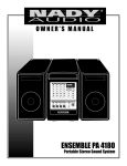
1
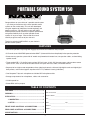
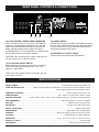
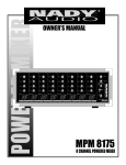
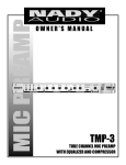
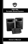
OWNER’S MANUAL
Portable Sound System 150
PORTABLE SOUND SYSTEM 150
Congratulations on your choice of a portable sound system
— you have purchased one of the finest portable sound
systems on the market today. This unit was developed
using the expertise of professional sound engineers and
working musicians. You will find that your new NADY
AUDIO portable sound systems has superior performance
and greater flexibility than any other portable sound
systems in its price range. Please read this manual
carefully to get the most out of your new unit.
Thanks for selecting NADY AUDIO as your choice in
portable sound systems.
FEATURES
• Convenient portable PA package with luggage-style handle and wheels for easy transport
• 5-Channel stereo 150W RMS powered mixer AMA™ (Automatic Maximum Amplitude) limiter speaker protection
• Stereo two-way speaker system with 10" woofer and piezoelectric tweeter horn, two speaker cables, and two folding
speaker stands
• Three combo XLR / 1/4" mic/line inputs and one XLR mic input, all with 15V phantom power, and two stereo source
inputs for CD, VCR, or DVD or other audio sources. All inputs with bass, treble, and reverb controls.
• Separate left and right master output 60mm linear fader level controls, choice of eight digital reverb and eight digital
delay effects, and five-band graphic equalizer with FLI™ (Feedback Locating Indicators).
• One Starpower™ dynamic microphone and 20 foot XLR microphone cable
• Storage compartments for microphones, cables and accessories
• Variable-speed fan
• Stereo RCA auxiliary outputs
TABLE OF CONTENTS
FEATURES ....................................................................... 2
Date of Purchase ____________________________________
WARNING ......................................................................... 3
Dealer’s Name ______________________________________
INTALLATION ................................................................... 4
City _______________________________________________
1. INSPECTION .......................................................... 4
State _____________________ Zip _____________________
2. SETUP .................................................................... 4
FRONT PANEL CONTROLS & CONNECTIONS ............ 5
Model # ____________________________________________
REAR PANEL CONTROLS & CONNECTIONS .............. 7
Serial # ___________________
SPECIFICATIONS ............................................................ 7
2
WARNING
An equilateral triangle enclosing a lightening flash/arrowhead symbol is
intended to alert the user to the presence of uninsulated “dangerous
voltage” within the product’s enclosure which may be of sufficient
magnitude to constitute a risk of electric shock.
ATTENTION: RISQUE DE CHOC ELECTRIQUE NE PAS OUVRIR
An equilateral triangle enclosing an exclamation point is intended to alert
the user to the presence of important operating and service instructions in
the literature enclosed with this unit.
IMPORTANT SAFETY INSTRUCTIONS
When using this electronic device, basic precautions should always be taken, including the following:
1.
Read all instructions before using the product.
2.
Do not use this product near water (e.g., near a bathtub, washbowl, kitchen sink, in a wet basement, or near a swimming
pool, etc.).
3.
4.
This product should be used only with a cart or stand that will keep it level and stable and prevent wobbling.
This product, in combination with headphones or speakers, may be capable of producing sound levels that could cause
permanent hearing loss. Do not operate for a long period of time at a high volume level or at a level that is uncomfortable.
If you experience any hearing loss or ringing in the ears, you should consult an audiologist.
5.
6.
The product should be positioned so that proper ventilation is maintained.
The product should be located away from heat sources such as radiators, heat vents, or other devices
(including amplifiers) that produce heat.
7.
The product should be connected to a power supply only of the type described in the operating instructions or as marked on the
product. Replace the fuse only with one of the specified type, size, and correct rating.
8.
The power supply cord should: (1) be undamaged, (2) never share an outlet or extension cord with other devices so that the
outlet’s or extension cord’s power rating is exceeded, and (3) never be left plugged into the outlet when not being used for
a long period of time.
9.
Care should be taken so that objects do not fall into, and liquids are not spilled through, the enclosure’s openings.
10. The product should be serviced by qualified service personnel if:
A.
The power supply cord or the plug has been damaged.
B.
Objects have fallen into, or liquid has been spilled onto the product.
C.
The product has been exposed to rain.
D.
The product does not appear to operate normally or exhibits a marked change in performance.
E.
The product has been dropped, or the enclosure damaged.
11. Do not attempt to service the product beyond what is described in the user maintenance instructions. All other servicing should
be referred to qualified service personnel.
3
INSTALLATION
Please make sure that the power unit supplied is marked
for the correct voltage in your area (120VAC/60 Hz or
230VAC/50 Hz). Power requirements for electrical
equipment differ from area to area. In new installations and
portable sound systems, or any situation in which the AC
power is in question, it is wise to confirm the voltage and
use the appropriate power supply unit before connecting it
to power sources.
To ensure years of enjoyment from your NADY AUDIO
Portable Sound System 150, please read and understand
this manual thoroughly before using the unit.
1. INSPECTION
Your NADY AUDIO Portable Sound System 150 was
carefully packed at the factory in packaging designed to
protect the units in shipment. Before installing and using
your unit, carefully examine the packaging and all contents
for any signs of physical damage that may have occurred in
transit.
Europe (except UK): 230V, 50Hz
UK and Australia: 240V, 50Hz
USA and Canada: 120V, 60 Hz
For other areas, please check with local authorities.
[Please note: Nady Systems is not responsible for shipping
damage. If your unit is damaged, do not return to Nady,
but notify your dealer and the shipping company (if
shipped to you) immediately to make a claim. Such claims
must be made by the consignee in a timely manner.]
Speakers and Stands
Fully extend the speaker stand tripod legs and tighten the
base thumbscrew. Extend the pole of the stand to the
desired height and insert the safety pin completely through
the stand hole above the pole thumbscrew. Lower the pole
so that the pin rests on the holder and tighten the pole
thumbscrew.
CONTENTS:
• PSS-150 Mixer Section
• PSS-150 Left Speaker
• PSS-150 Right Speaker
• (2x) Speaker Stands
• (2x) 2 30' Speaker Cables
• SP-1 Starpower™ Microphone
• XC-20 20' Microphone Cable
• AC cord
• Instruction Manual
• Warranty Card
Setup the stands on a flat surface where the speakers will
be located and not disturbed. Place the speakers on the
stands and position them as desired. Note: facing the
speakers towards any of the microphones connected with
the PSS-150 will increase the chance of feedback.
Connect the speaker cables to the input jacks on the lower
left front panel of both the Left and Right speakers.
Connect the other end of each cable to the corresponding
Left and Right speaker outputs on the rear panel of the
PSS-150 mixer section. Position the length of the cables
so they will not be a safety hazard to people.
2. SETUP
After transporting the PSS-150 to the desired location, lay
the unit down on its flat side. Unclasp the side panel
latches by pulling up on the yellow tab to release and
unhook the latch. Carefully lift off the speakers and then
remove the speaker stands and accessories from inside the
unit.
WARNING: Connect only the supplied speakers to the
PSS-150. Never connect additional speakers to the
PSS-150.
Mixer Section
Position the PSS-150 mixer section on its flat surface with
the control panel facing up. Parts of the unit can become
very warm during use. This is normal during operation.
Care should be taken to ensure that there is enough space
behind the Mixer Section for cooling. Also, do not place the
Portable Sound System on high temperature devices such
as power amplifiers, etc., or the unit may overheat in
operation.
Inputs
Connect all sound sources to the appropriate inputs i.e.,
microphones, keyboards, CD players, karaoke machines.
The supplied SP-1 Starpower™ microphone is an allpurpose professional stage and recording microphone with
rugged metal construction and excellent clear, transparent
sound across the spectrum.
Although the Portable Sound System is shielded against
radio frequency (RF) and electromagnetic interference
(EMI), extremely high fields of RF and EMI should be
avoided.
When ready to operate, plug the AC cord into the power
source. Make sure that the unit is turned off before
connecting to the AC power source to avoid possible loud
transients which can damage your speakers or your ears.
Before turning on, connect up the speakers and all inputs
and outputs desired and turn down the Master Volume.
4
FRONT PANEL CONTROLS & CONNECTIONS
(1)
(2)
(3) (14)
(4)
(13)
(5)
(6)
(15)
(7)
(8)
(9)
(10) (11)(12)
In is sent to the Right Speaker. When the button is
depressed (Stereo mode), both L and R RCA input signals
are mixed and sent to both speakers.
(1) CHANNEL 1-3 COMBO XLR / 1/4' INPUT
The XLR mic inputs are an electronically balanced XLR
type designed to accept mic level signals from any
balanced or unbalanced low impedance (Low Z)
microphone. The XLR jacks are configured for: Pin1 =
ground, Pin2 = positive (+), Pin3 = negative (-). The XLR
jacks have 15VDC phantom power applied to Pin2 and 3
for powering condenser microphones.
(5) EFF SEND CONTROL
The EFF SEND control adjusts the level of signal sent by
each channel to the internal DSP (Digital Sound
Processor). The signal sent is mono, post-Treble/Bass and
will be affected by the CHANNEL FADER (8) setting.
The 1/4" mono line inputs are designed to accept
unbalanced line level signals such as those from
keyboards, drum machines, or samplers.
(6) TREBLE CONTROL
Turn to the right to boost high frequencies, adding
crispness too percussion from drum machines, cymbals
and synths. Turn to the left to cut these frequencies,
reducing sibilance or hiss. The control has a shelving
response giving +/-10dB of boost or cut at 10kHz.
(2) CHANNEL 4 XLR & 1/4" STEREO/MONO INPUTS
The XLR input is balanced, designed to accept mic level
signals, and has 15VDC phantom power. The Left and
Right 1/4" line inputs are for connecting stereo line level
audio signals or only the Left/Mono jack can be used for
connecting mono signals. The XLR input is defeated when
either of the 1/4" inputs are used.
(7) BASS CONTROL
The bass control shelving response gives 10dB of boost or
cut at 100Hz. Add warmth to vocals or extra punch to
guitars, drums and synths by turning to the right. Turn to
the left to reduce stage rumble, hum or to improve a mushy
sound.
(3) CHANNEL 5 STEREO RCA INPUTS
The stereo RCA line level inputs can be used for
connecting CD players, Tape Decks, and other audio
equipment with line level outputs.
(8) CHANNEL FADER
The channel faders determine the output signal level to the
Master Mix bus. They offer a smooth logarithmic taper
more often associated with much more expensive consoles
for optimum control of the signal.
(4) MONO / STEREO MODE
When the Mono/Stereo button is out (stereo mode) the Left
RCA Aux In is sent to the Left Speaker and Right RCA Aux
5
FRONT PANEL CONTROLS & CONNECTIONS
(Note: Observe care in selecting P.A. volume, microphone
location and speaker placement so that acoustic feedback
(howling and screeching) will be avoided. Please also
observe the pickup patterns of the microphone selected:
omnidirectional mics pick up sound equally from all
directions and are prone to feedback if not used carefully.
Unidirectional mics are more resistant to feedback, but
pick up sound sources best that are directly in front of the
mic. Also, mics that are farther from the sound source
require more acoustic gain andthus are also more prone to
feedback than close-source mics that are used close to the
mouth.)
(9) DSP EFFECTS DISPLAY
This is displays the selected effect out of 16 possible effect
presets.
(10) DSP EFFECTS SELECTOR
The UP/DOWN buttons allow fast and easy scrolling in
either direction through the 16 effect presets.
Effects List:
0 — Hall 1
1 — Hall 2
3 — Room 1
4 — Room 3
5 — Plate 1
6 — Plate 2
7 — Spring
8 — DLY 5ms
9 — DLY 10ms
A — DLY 20ms
B — DLY 30ms
C — DLY 200ms
D — DLY 300ms
E — DLY 400ms
F — DLY 500ms
(11) POWER ON INDICATOR
This LED lights blue when the unit is ON.
(14) AUX RCA OUTPUTS
The Left and Right RCA outputs provide line level signal
output to a cassette deck, home audio equipment, or a
recording device.
(12) 5-BAND GRAPHIC EQ
The 5-band channel graphic equalizer allows you to adjust
the frequency response of the L and R Channel bus signal,
providing a maximum of ±12dB of cut and boost for each
frequency band from the flat position. The faders can be
adjusted to easily eliminate feedback from the
corresponding FLI™.
(15) L/MONITOR and R/MAIN MASTER FADERS
These control the final level of the signal sent to the left and
right SPEAKER OUTPUTS (19) outputs and the AUX RCA
OUTPUTS (14). These are also named Monitor and Main
for situations when the Left speaker will be used as a
monitor for the performers and the Right speaker will be
positioned towards the audience.
(13) FEEDBACK LOCATING INDICATORS (FLI™)
These LED indicators will light red when there is a high
level audio signal at the indicated frequency. These can be
used to detect an audio feedback frequency and then lower
the appropriate EQ fader to remove the unwanted
feedback.
6
REAR PANEL CONTROLS & CONNECTIONS
(18)
(16)
(17)
(19)
(18) POWER SWITCH
Use this switch to power unit ON or OFF. Before turning on
this unit, verify connection to the proper voltage AC source,
check all connections and turn down the level controls of
equipment connected to the outputs.
(16) FUSE HOLDER & POWER CORD CONNECTOR
This fuse holder contains an AC primary fuse. When this
fuse blows, replace it with the same type fuse, size and
power rating (see SPECIFICATIONS). If it continuously
blows, stop replacing the fuse and refer servicing to
qualified personnel. The cord connector is used to connect
the AC power source to your power amplifier.
(19) SPEAKER 1/4” OUTPUT JACKS
Connect to the left and right PSS-150 speakers.
(CAUTION: After checking the AC supply voltage, be sure
that the correct fuse is in the fuse holder.)
(17) AC VOLTAGE SELECT SWITCH
Before plugging in the power cord, check to see that the
unit is set for the proper voltage for your area: ~115V
(60Hz) or ~230V (50Hz).
(Note: use at the improper voltage can damage your unit
and void the warranty.)
SPECIFICATIONS
OUTPUT POWER ........................................................................................................... 75 watts RMS per channel into 4 Ohms load
OVERLOAD PROTECTION ...................... AMA™ (Automatic Maximum Amplitude) servo system limits the power amplifier input to
prevent clipping distortion that can damage speakers
FREQUENCY RESPONSE .......................................................................................................... 40 Hz to 20 KHz measured at 1 watt
TONE CONTROLS ................................................................................................. Bass: 100 Hz ±+/-10 dB; Treble: 10 KHz +/-10 dB
GRAPHIC EQUALIZER .................. 5 bands; 100 Hz, 350 Hz, 1 KHz, 3 KHz, and 8 KHz with FLI™ (Feedback Locating Indicators)
INPUT IMPEDANCE ....................................................................................................... Mic input: 2 K Ohms, Line input: 12 K Ohms
MAX GAIN ....................................................................................................................................... 86 dB mic input to speaker output
DISTORTION ................................................................................................................................Less than 0.8% THD at rated output
SIGNAL / NOISE RATIO ................................................................................................................................... 85 dB mic input typical
REVERB/DELAY ........................................................................................................................... DSP digital reverb and digital delay
SPEAKERS .......................................................................................................... Woofer 10" (254mm) and piezoelectric horn tweeter
AC POWER ........................................................................................................................... 120 VAC(60 Hz0 or 230 VAC (50/60 Hz)
DIMENSIONS ....................................................................................................... 27.6" x 15.75" x 23.4" (70.2 cm x 40 cm x 59.4 cm)
WEIGHT (assembled) .................................................................................................................................................. 59.4 lbs (27Kg)
MICROPHONE .................................................................................................................................. Unidirectional (cardioid) dynamic
7
SERVICE FOR YOUR NADY AUDIO PRODUCT
(U.S.) Should your NADY AUDIO product require service, please contact the Nady Service Department via telephone
at (510) 652-2411, or e-mail at [email protected].
(International) For service, please contact the NADY AUDIO distributor in your country through the dealer from
whom you purchased this product.
DO NOT ATTEMPT TO SERVICE THIS UNIT
YOURSELF AS IT CAN BE DANGEROUS AND
WILL ALSO VOID THE WARRANTY.
NADY SYSTEMS, INC. • 6701 SHELLMOUND STREET, EMERYVILLE, CA 94608
Tel: 510.652.2411 • Fax: 510.652.5075 • www.nady.com