1
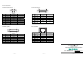
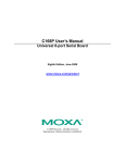
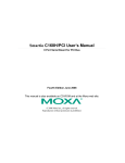
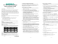
4. Software Installation Information CP-118U Smart Serial Board Quick Installation Guide The board MUST be plugged in before installing the driver. See the previous section for instructions on how to install the board in your PC. Refer to the CP-118U User’s Manual for detailed instructions on installing the drivers for this board. Windows 2003/XP Driver Installation Third Edition, January 2005 1. Overview CP-118U is an 8-port RS-232/422/485 Universal PCI serial board ideal for connecting a wide range of serial devices—including terminals, modems, printers, scanners, cash registers, bar code readers, keypads, numeric displays, electronic scales, and data acquisition equipment—to a PC. The board’s device drivers make full use of the 128-byte Tx/Rx FIFO and on-chip H/W and S/W flow control, which allow data transmission at speeds of up to 921.6 Kbps. 2. Package Checklist Before installing the CP-118U board, verify that the package contains the following items: y 1 CP-118U 8-port serial board y Documentation and Software CD, which contains drivers for Windows 2000/XP/2003, Windows NT, Windows 95/98, DOS, FreeBSD, SCO, and Linux. y CP-118U Quick Installation Guide Notify your sales representative if any of the above items is missing or damaged. 3. Hardware Installation Procedure The CP-118U board MUST be plugged into the PC before the driver is installed. Follow these steps to install the board in the PC. STEP 1: Power off the PC. STEP 2: Use the DIP switches on the board to select the serial interface. Refer to the Mode vs. DIP switch table below (also shown on the board): Mode S1 S2 S3 RS-232 ----ON RS-422 --ON OFF 4-WIRE ON OFF OFF RS-485 2-WIRE OFF OFF OFF RS-485 STEP 3: Plug the CP-118U control board firmly into an open PCI or PCI-X slot. STEP 4: Fasten the holding screw to fix the control board in place. STEP 5: Power on the PC; the BIOS will automatically set the IRQ and I/O address. STEP 6: Proceed with installing the driver, as described in the next section. P/N: 18020011802 —1— 1. After powering on your PC, Windows 2003/XP will automatically detect the CP-118U board. 2. Insert the CP-118U software CD in your CD-ROM drive. 3. Select Install from a list or specific location (Advanced). 4. After selecting Search for the best driver in these locations, check the Include this location in the search checkbox, and then use the browse button to navigate to the CD’s CP-118U\Software\Win2K-XP-2003 folder. 5. Click on Continue Anyway in response to any warnings that the software hasn’t passed Windows Logo testing. 6. After the board has been installed, the installation wizard will guide you through the port installation procedure, starting with port 0. 7. If the board appears to be installed incorrectly, use the Device Manager to check the installation of the board and ports. Click on the + sign next to Hardware, and then check under Multi-port serial adapters and Ports (COM & LPT). If there are no warning marks, such as a question mark or exclamation point in front of the board or port icons, examine the Event Log to determine what the problem is. Windows 2000 Driver Installation 1. After powering on your PC, Windows 2000 will automatically detect the CP-118U board. 2. Insert the CP-118U software CD in your CD-ROM drive. 3. Select Search for a suitable driver for my device (recommended). 4. In Optional search location, checkmark specify a location. Navigate to the \CP-118U\Software\Win2K-XP-2003 folder on the software CD, and then click on OK to continue. 5. Click on Continue Anyway in response to any warnings that the software hasn’t passed Windows Logo testing. 6. After the board has been installed, the installation wizard will guide you through the port installation procedure, starting with port 0. 7. If the board appears to be installed incorrectly, use the Device Manager to check the installation of the board and ports. Click on the + sign next to Hardware, and then check under Multi-port serial adapters and Ports (COM & LPT). If there are no warning marks, such as a question mark or exclamation point in front of the board or port icons, examine the Event Log to determine what the problem is. —2— Windows 95/98 Driver Installation 1. After powering on your PC, Windows 95/98 will automatically detect the CP-118U board. 2. Insert the CP-118U software CD in your CD-ROM drive. 3. There are differences between the installation procedures for Windows 95 and Windows 98. However, in both cases, be sure to install the driver from the CD’s CP-118U\Software\Win9x\Windows.95 folder. 4. After the board has been installed, the installation wizard will open the port configuration window. NOTE: If an error message similar to “CP-118U board (BusNo=x, DevNo=x, Port1=COMx) interrupt number is invalid!” pops up, refer to the “Troubleshooting” chapter of the User’s Manual for information on how to handle this error. Windows NT Driver Installation 1. After powering on your PC, log into NT as Administrator. 2. Copy the folder CP-118U\Software\WinNT\Windows.nt to your hard drive. 3. Open the Control Panel, click on the Network icon, and select the Adaptors tab. 4. Click the Add button, and then Have Disk… in the Select Network Adapter window. 5. Specify the exact path to the folder created in Step 2 above. 6. Select MOXA Smartio/Industio Family multiport board in the Select OEM Option window, and then click on OK to start installing the driver. 7. When the Moxa Smartio/Industio Configuration Panel dialog box appears, click on Add to open the Property window to modify port settings and advanced FIFO configuration done automatically by the system. Linux Driver Installation 1. Execute the following commands from the Linux prompt: #mount /dev/cdrom /mnt/cdrom #cd / #mkdir moxa #cd moxa #cp /mnt/cdrom/<driver directory>/mxser.tgz . #tar xvfz mxser.tgz 2. #cd mxser #make clean; make install 3. #cd /moxa/mxser/driver #./msmknod 4. #modprobe mxser 5. Use the Moxa diagnostic utility to verify the driver status: #cd /moxa/mxser/utility/diag #./msdiag 6. Use the Moxa terminal utility to test the tty ports: #cd /moxa/mxser/utility/term #./msterm —3— 5. Pin Assignments Male DB9 (Opt8-D/Opt8-M9) 1 6 Pin RS-232 1 2 3 4 5 6 7 8 9 DCD RxD TxD DTR GND DSR RTS CTS --- Female DB25 (Opt8A/S) 13 5 9 25 RS-422 / 4-wire RS-485 TxD-(A) TxD+(B) RxD+(B) RxD-(A) GND --------- 2-wire RS-485 ----Data+(B) Data-(A) GND --------- Pin RS-232 2 3 4 5 6 7 8 20 RxD TxD CTS RTS DTR GND DCD DSR 14 RS-422 / 4-wire RS-485 TxD+(B) RxD+(B) ----RxD-(A) GND TxD-(A) --- RS-232 2 3 4 5 6 7 8 20 TxD RxD RTS CTS DSR GND DCD DTR --Data+(B) ----Data-(A) GND ----- 14 1 Pin 2-wire RS-485 RJ45 (Opt8-RJ45) Male DB25 (Opt8B/C) 1 13 1 25 RS-422 / 4-wire RS-485 RxD+(B) TxD+(B) ------GND TxD-(A) RxD-(A) 2-wire RS-485 Data+(B) --------GND --Data-(A) Pin RS-232 1 2 3 4 5 6 7 8 DSR RTS GND TxD RxD DCD CTS DTR 8 RS-422 / 4-wire RS-485 ----GND RxD+(B) TxD+(B) TxD-(A) --RxD-(A) 2-wire RS-485 ----GND Data+(B) ------Data-(A) Copyright 2005 Moxa Technologies Co., Ltd. All rights reserved. Reproduction without permission is prohibited. Tel: +886-2-8919-1230 Fax: +886-2-8919-1231 —4— —5— www.moxa.com [email protected] —6—