1
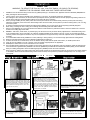
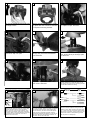
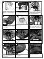
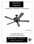
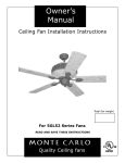
Owner’s
Manual
Ceiling Fan Installation Instructions
Total fan weight
For 5MQ60XX Series Fans
READ AND SAVE THESE INSTRUCTIONS
Quality Ceiling fans
Installation
SAFETY TIPS
WARNING: TO REDUCE THE RISK OF FIRE, ELECTRIC SHOCK, OR INJURY TO PERSONS,
OBSERVE THE FOLLOWING: READ AND SAVE THESE INSTRUCTIONS
1.
2.
3.
4.
5.
6.
7.
8.
9.
10.
11.
12.
13.
14.
15.
Installation work and electrical wiring must be done by qualified person(s) in accordance with applicable codes and standards (ANSI/NFPA 701999), including fire-rated construction.
Use this unit only in the manner intended by the manufacurer. If you have any questions contact the manufacturer.
After making the wire connections, the wires should be spread apart with the grounded conductor and the equipment-grounding conductor on
one side of the outlet box and ungrounded conductor on the other side of the outlet box.
Before you begin installing the fan, Switch power off at Service panel and lock service disconnecting means to prevent power from being
switched on accidentally. When the service disconnecting means cannot be locked, securely fasten a prominent warning device, such as a tag,
to the service panel.
Be cautious! read all instructions and safety information before installing your new fan. Review the accompanying assembly diagrams.
When cutting or drilling into wall or ceiling, do not damage electrical wiring and other hidden utilities.
Make sure the installation site you choose allows the fan blades to rotate without any obstructions. Allow a minimum clearance of 7 feet from
the floor to the trailing edge of the blade.
WARNING – Risk of fire, electric shock, or personal injury, The fan in this box may be either directly supported from a structural framing member of a building and/or may be mounted to an outlet box marked acceptable for fan support of 31.8 kg. (70 lbs.) or less. Most outlet boxes
commonly used for the support of luminaires may not be acceptable for fan support and may need to be replaced. Consult a qualified electrician
if in doubt.
Do not bend blade holders during installation to motor, balancing or during cleaning. Do not insert foreign object between rotating blades.
Attach the mounting bracket using only the hardware supplied with the outlet box.
To reduce the risk of fire or electric shock, do not use this fan with any solid state fan speed control device, or variable speed control.
If this unit is to be installed over a tub or shower, it must be marked as appropriate for the application.
NEVER place a switch where it can be reached from a tub or shower.
The combustion airflow needed for safe operation of fuel-burning equipment may be affected by this unit’s operation. Follow the heating equipment manufacturer’s guideline safety standards such as those published by the National Fire Protection Association (NFPA), and the American
Society for Heating, Refrigeration and Air Conditioning Engineers (ASHRAE) and the local code authorities.
Before servicing or cleaning unit, Switch power off at Service panel and lock service disconnecting means to prevent power from being switched
on accidentally. When the service disconnecting means cannot be locked, securely fasten a prominent warning device, such as a tag, to the
service panel.
Phillips Screwdriver
1
TOOLS REQUIRED
Wire Cutters
Pliers
Before you begin installing the fan, Switch
power off at Service panel and lock service disconnecting means to prevent power from being
switched on accidentally. When the service disconnecting means cannot be locked, securely
fasten a prominent warning device, such as a
tag, to the service panel.
4
2
OUTLET BOX METHOD
Warning-Risk of fire, electric shock, or personal injury. The fan in this box may be either
directly supported from a structural framing
member of a building and/or may be mounted
to an outlet box marked acceptable for fan support of of 31.8 kg (70 lbs) or less. Most outlet
boxes commonly used for the support of lumminaires may not be acceptable for fan support
and may need to be replaced. Consult a qualified electrician if in doubt.
5
BUILDING STRUCTURE METHOD
Outlet box
3
Step Ladder
Remove Safety bar from mounting bracket by
loosing screws, sliding bar to side, and lifting it
off the 2 screws.
6
FAN BRACE AND BOX METHOD
Mounting
Plate
Wood
Screws
Remove the 4 screws attaching the Mounting
neck the mounting plate. Retain the 4 screws
for re-assembly.
Secure mounting plate directly to a joist from
the buliding structure via the two knock out
holes on the outlet box. Use only the appropriate wood screws and washers included with
your fan. Caution: Wood screws must go
through into the building joist.
Install the mounting Plate to approved fan
brace and box combination use only the hardware provided with the fan brace and box.
7
8
9
Lift mounting neck to mounting Plate
and align screws.
Secure mounting neck to the mounting plate with four screws to become
a complete mounting bracket.
Remove keeper from pin. Remove
pin replace keeper and save.
10
11
12
Loosen the 2 set screws in yoke for
downrod to slip into yoke.
Thread wire through downrod with
canopy and yoke cover assembled
onto downrod.
Insert downrod into motor yoke.
Next, insert clevis pin through yoke
and downrod.
13
14
15
Tighten both yoke set screws to further secure downrod.
Carefully lift fan assembly onto mounting
bracket. Rotate fan so that the notch on the
ball engages the ridge in the mounting bracket.
This will allow hands-free wiring.
17
18
Secure with cotter pin.
16
Safety cable installation
Black
Safety Cable
Lag Screw
White
Green
safety
cable
lock
washer
Fan and light kit combinations over 70 lbs, in
both flush and downrod mode the safety cable
must be installed into the house structure
beams using the 3” lag screws,washers, and
lock washers. provided. Make sure that when
the safety cable is fully extended the lead wires
are longer than the cable and no stress is
placed on the lead wires.
Fan
Black
Blue
White
Green(downrod)
Green(Bracket)
washer
3” lag
screw
House
Make wire connections to power source using
wire nuts provided. Make sure that no filiments
are outside of the wirenut. After making the
wire connections, the wires should be spread
apart with the grounded conductor and the
equipment-grounding conductor on one side of
the outlet box and ungrounded conductor on
the other side of the outlet box.
For pullchain controls, follow diagram above.
Make sure that all exposed wiring is secured
inside wire nuts. Note: Wires from house may
vary in color and may not include ground wire.
After wiring is conplete, gently push wires into
junction box with wire nuts pointing upward.
Refer to point 3 of safety tips.
20
21
Re-install safety bar removed in
step. 3 by placing safety bar on
screws, sliding into place, and tightening the 2 screws.
Raise the canopy up and align the
two holes in the canopy with the two
holes in the hanger bracket. Secure
with two screws provided.
23
24
Remove the steel motor stabilizing
plate and discard.
The screws, washers, and motor
pads are pre-installed to the blade
holders. Attach blade assembly to
motor and tighten screws securely.
25
26
27
Loosen 3 screws with key slots and
remove 1 screw without slot from
motor plate and save screw.
Install switch housing plate by twisting plate with key hole slots into
place. Replace screw removed and
tighten the 4 screws securely.
Connect plug from fan to switch
house plug.
28
29
30
Fan Switch
Light Switch
19
Wall
Control
For control of fan and optional light from wall
location, follow diagram above. NOTE: A professional electrician is recommended for this type
of installation.
22
Install 3 screws and washers per
blade and tighten securely. Repeat
for all 5 blades
capacitor
Remove the double sided tape from
capacitor and stick capacitor to
switch housing.
Remove 4 screws and save to install
switch housing.
Install the switch housing using the 4
screws previously removed.
Trouble Shooting
If you have difficulty operating your new ceiling fan, it may be the result of incorrect assembly, installation,
or wiring. In some cases, these installation errors may be mistaken for defects. If you experience any faults,
please check this Trouble Shooting Chart. If a problem cannot be remedied, or you are experiencing difficulty
in installation, please call our Customer Service Center at the number printed on your parts list insert sheet.
Warning: Before servicing or cleaning unit, Switch power off at Service panel and lock service disconnecting means to prevent power from being switched on accidentally. When the service disconnecting means cannot be locked, securely fasten a prominent warning device, such as a tag,
to the service panel.
1. If fan does not start:
2. If fan sounds noisy:
1.Check main and branch circuit fuses or circuit breakers.
2.Check line wire connections to fan and switch wire connections in switch housing.
3.Check to make sure the dip switches from the transmitter and receiver are set on the same
frequency.
CAUTION: Make sure main power is turned off.
1.Check to make sure
2.Check to make sure
3.Check to make sure
or against the interior
all screws in motor housing are snug (not over tightened).
the screws which attach the fan blade holder to the motor are tight.
wire nut connectors in switch housing are not rattling against each other
wall of the switch housing.
CAUTION: Make sure main power is turned off before entering switch housing.
4.Some fan motors are sensitive to signals from Solid State variable speed controls.
DO NOT USE a Solid State variable speed control.
3. If fan wobbles:
4. If light does not work:
5.Allow "break-in" period of 24 hours. Most noises associated with a new fan will disappear
after this period.
1.Make sure that the ridge of the canopy engages the notch in the downrod ball.
2.Check that all blades are screwed firmly into blade holders.
3.Check that all blade holders are tightened securely to motor.
4.Make sure that canopy and mounting bracket are tightened securely to ceiling junction box
and junction box is mounted firmly to ceiling joist.
5.Most fan wobble problems are caused when blade levels are unequal. Check this level by
selecting a point on the ceiling above the tip of one of the blades. Measure this distance from
blade tip to ceilng. Keeping measure within 1/8", rotate the fan until the next blade is positioned for measurement. Repeat for each blade. If all blade levels are not equal, you can adjust
blade levels by the following procedure. To adjust a blade tip down, insert a washer (not supplied) between the blade and blade holder at the screw closest to the motor. To adjust a blade
tip up, insert washer (not supplied) between the blade and blade holder at the two screws farthest from the motor. Reverse the position of the washer if blades mount from top of blade.
6.If blade wobble is still noticeable, interchanging two adjacent (side by side) blades can redistribute the weight and possibly result in smoother operation.
1.Check
2.Check
3.Check
4.Check
wire from fan to make sure it is connected to hot wire from house.
for loose or disconnected wires in fan switch housing.
for loose or disconnected wires in light kit.
for faulty light bulbs.
CAUTION: Make sure main power is turned off before entering switch housing.
Customer Service Center
740 S.W. Loop 820, Suite 110
Fort Worth, Texas 76115
1-800-519-4092