1
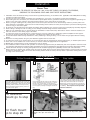
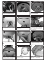
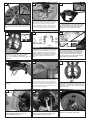
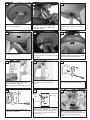
OWNER’S
MANUAL
Ceiling Fan Installation Instructions
Total fan weight
with light
For 3ASR52XXD Series Fans
READ AND SAVE THESE INSTRUCTIONS
QUALITY CEILING
FANS
Installation
SAFETY TIPS
WARNING: TO REDUCE THE RISK OF FIRE, ELECTRIC SHOCK, OR INJURY TO PERSONS,
OBSERVE THE FOLLOWING: READ AND SAVE THESE INSTRUCTIONS
1. Installation work and electrical wiring must be done by qualified person(s) in accordance with applicable codes ANSI/NFPA 70-1999),
including fire-rated construction.
2. Use this unit only in the manner intended by the manufacturer. If you have any questions contact the manufacturer.
3. After making the wire connections, the wires should be spread apart with the grounded conductor and the equipment-grounding conductor on one side of the outlet box and ungrounded conductor on the other side of the outlet box.
4. Before you begin installing the fan, Switch power off at Service panel and lock service disconnecting means to prevent power from
being switched on accidentally. When the service disconnecting means cannot be locked, securely fasten a prominent warning device,
such as a tag, to the service panel.
5. Be cautious! read all instructions and safety information before installing your new fan. Review the accompanying assembly diagrams.
6. When cutting or drilling into wall or ceiling, do not damage electrical wiring and other hidden utilities.
7. Make sure the installation site you choose allows the fan blades to rotate without any obstructions. Allow a minimum clearance of 7
feet from the floor to the trailing edge of the blade.
8. To reduce the risk of fire, electric shock, or personal injury, mount to outlet box or supporting system acceptable for fan support.
Use only the screws provided with the outlet box. (Mounting must support at least 35 lbs.)
9. Do not bend blade holders during installation to motor, balancing or during cleaning. Do not insert foreign object between rotating
blades.
10. Attach the mounting bracket using only the hardware supplied with the outlet box.
11. To reduce the risk of fire or electric shock, do not use this fan with any solid state fan speed control device, or variable speed control.
12. If this unit is to be installed over a tub or shower, it must be marked as appropriate for the application.
13. NEVER place a switch where it can be reached from a tub or shower.
14. The combustion airflow needed for safe operation of fuel-burning equipment may be affected by this unit’s operation. Follow the heating equipment manufacturer’s guideline safety standards such as those published by the National Fire Protection Association (NFPA),
and the American Society for Heating, Refrigeration and Air Conditioning Engineers (ASHRAE) and the local code authorities.
15. Before servicing or cleaning unit, Switch power off at Service panel and lock service disconnecting means to prevent power from being
switched on accidentally. When the service disconnecting means cannot be locked, securely fasten a prominent warning device, such
as a tag, to the service panel.
1
Phillips Screwdriver
Before you begin installing the fan, Switch
power off at Service panel and lock service disconnecting means to prevent power from being
switched on accidentally. When the service disconnecting means cannot be locked, securely
fasten a prominent warning device, such as a
tag, to the service panel.
2
TOOLS REQUIRED
Wire Cutters
Pliers
Before installing this fan make sure the outlet box is
properly installed to the house structure. To reduce
the risk of fire, electric shock, or personal injury,
mount to outlet box or supporting system acceptable
for fan support. (Mounting must support at least 35
lbs.)
4
5
For flush mount
go to step 29
Remove keeper from pin. Replace
keeper into pin and save for
later.
For downrod
mount go to step
5
3
Step Ladder
Use metal outlet box suitable for fan support
(must support 35 lbs). Before attaching fan to
outlet box, ensure the outlet box is securley
fastened by at least two points to a structural
ceiling member ( a loose box will cause the fan
to wabble). Use only the screws provided
with the outlet box.
6
Loosen the 2 set screws in yoke
for downrod to slip into yoke.
7
8
9
Place canopy, canopy ring and
then yoke cover on downrod.
Thread leadwires and safety
cable through downrod. As
shown.
Insert downrod into yoke on top of the Fan
Body. Align the hole in the Downrod with the
hole in the Yoke. Insert the Pin through the
Yoke and Downrod until the point appears on
the other side. Install the keeper to pin.
Tighten the 2 set screws on the Yoke
once the downrod is in place.
10
Safety cable installation
11
12
Make sure the studs protruding from the
bottom of the Mounting bracket are
installed with threads all the way through
the bracket.
Hang assembled fan from the mounting bracket
installed to ceiling in previous step. Make sure the
fan is hanging straight. Rotate fan until the tab on
the Mounting bracket engages the slot on the
Downrod Ball. This must be done to prevent the fan
body from rotating when the blades are in motion.
Safety Cable
Lag Screw
safety
cable
washer
3” lag
screw
lock
washer
For Canadian installation and for USA fan and
light kit combinations over 35 lbs, in both flush
and downrod mode the safety cable must be
installed into the house structure beams using
the 3” lag screws,washers, and lock washers.
provided. Make sure that when the safety cable
is fully extended the leadwires are longer than
the cable and no stress is placed on the leadwires.
13
14
15
white
black
Remote Transmitter Dip swtiches
Remote Receiver Dip switches
Make wiring connections as indicated above.
White from fan to white from remote marked
N. Blue from fan to blue from remote marked
light. Black from fan to Black from remote
marked L. White from house to white from
remote marked AC N . Black from house to
Black from remote marked AC L. Connect all
green ground wires to Ground wire from
House.
Set dip switches on the Remote Transmitter and Remote
Receiver to the same settings. This must be done so the
units will communcate properly. If you have other fans you
can set to control from one transmitter by setting both
receivers the same as the transmitter. If you have more
than one fan with remote. You can set the dip switches to
different positiosns to have seperate control.
16
17
18
Make wire connections to power source using wire nuts
provided. Make sure that no filiments are outside of
the wirenut. After making the wire connections, the
wires should be spread apart with the grounded conductor and the equipment-grounding conductor on one
side of the outlet box and ungrounded conductor on
the other side of the outlet box.
Next lift the cover ring and install knurled
nuts as shown. Tighten the knurled nuts
securely. The canopy should adjust for
any irregularity in the ceiling or Outlet
box.
Align the blade and then the blade
plate with castings on motor to
attach blades to motor.
Slide remote receiver into mounting
bracket.
Blade plate
19
Loosen 2 screws with key slots and
remove 1 screw without slot from
motor plate and save screw.
20
Install light plate by twisting plate
with key hole slots into place.
21 Go to step 24 for Light kit
Replace screw removed and tighten
the 3 screws securely.
22
23
24
Install light plate over all thread and
use nut provided to secure in place.
Attach blanking plate to fan by twisting into place.
25
Connect white wire from fan to white
wire from light fixture. Then plug
black wire from fan to black wire
from light fixture.
26
27
Install light fixture over all thread
and use nut provided to secure in
place.
Attach decorative cap to light fixture
by twisting into place.
28
29 Flush Mount Instalation
Install 1 x 100 halogen bulb E-11.
Do not touch bulb surface as oily
residue from skin can cause the bulb
to explode.
30
Pass leadwires and safety cable
through the canopy.
Remove side covers from canopy
exposing 4 holes. 2 closed holes
and 2 open “L” shape holes.
Attach glass by locating dimples in
light fixture with the groves in glass
and twisting clockwise till tight.
32
31
Center
Hole
Canopy
33
Larger
holes
Smaller
holes
Remove 2 screws in yoke and keeper
then cross pin (see insert). Remove 3
screws with keyhole slots from top of
fan.
34
Hands free hook
Place canopy on top of the fan motor allowing the
yoke, wires and safety cable to pass through the
large hole in the center of the canopy. Align the 3
larger holes around the center hole with the 3
screws still installed in the fan. Install 3 screws
removed into small holes in canopy to make it a
flush mount canopy and tighten screws securely.
Install two screws corresponding with the
“L” shaped holes in the canopy only part
way so that canopy can twist into place.
Remove the all thread studs from the
lower part of the mounting bracket.
35
36
white
black
Remote Transmitter Dip swtiches
Remote Receiver Dip switches
Make wiring connections as indicated above.
White from fan to white from remote marked
N. Blue from fan to blue from remote marked
light. Black from fan to Black from remote
marked L. White from house to white from
remote marked AC N . Black from house to
Black from remote marked AC L. Connect all
green ground wires to Ground wire from
House.
Set dip switches on the Remote Transmitter and Remote
Receiver to the same settings. This must be done so the
units will communcate properly. If you have other fans you
can set to control from one transmitter by setting both
receivers the same as the transmitter. If you have more
than one fan with remote. You can set the dip switches to
different positiosns to have seperate control.
37
38
39
Slide remote receiver into mounting
bracket.
Make wire connections to power source using wire nuts
provided. Make sure that no filiments are outside of
the wirenut. After making the wire connections, the
wires should be spread apart with the grounded conductor and the equipment-grounding conductor on one
side of the outlet box and ungrounded conductor on
the other side of the outlet box.
Lift fan to mounting bracket, aligning the “L”
shape holes with the scresws on the mounting bracket. Turn the fan clockwise to lock
in position. Install the other two screws and
tighten securely.
Hang fan from mounting bracket by
the hands free hook into a closed
hole on the edge of the Canopy.
Note: For Canadian mounting refer to
Step #10.
40
Blade plate
Align the blade and then the blade
plate with castings on motor to
attach blades to motor.
41
Loosen 2 screws with key slots and
remove 1 screw without slot from
motor plate and save screw.
42
Install light plate by twisting plate
with key hole slots into place. .
43
44
45
Connect white wire from fan to white
wire from light fixture. Then plug
black wire from fan to black wire
from light fixture.
Install light fixture over all thread
and use nut provided to secure in
place.
47
48
Install 1 x 100 halogen bulb E-11.
Do not touch bulb surface as oily
residue from skin can cause the bulb
to explode.
Attach glass by locating dimples in
light fixture with the groves in glass
and twisting clockwise till tight.
50
51
Remove cover by snapping off from
top or bottom. Install 12V battery
into wall remote. Duracell
MN21/Eveready A23/GP 23A all 12V
Attach cover of remote by placing
over buttons and snapping into
place.
Install wall control unit to outlet box
using machine screws provided.
52
53
54
Replace screw removed and tighten
the 3 screws securely
46
Attach decorative cap to light fixture
by twisting into place.
49
Fan speed
control
buttons
Light dimmer
for lights
Fan on / off
Attach front cover to wall control
with screws provided.
To control fan speed select from high,
medium or low speed buttons. To turn
the fan off press the Fan on / off button.
To dim lights press and hold light button. To turn off light press and quickly
release button.
Reverse function for this fan is a
switch on top housing of the fan
body. Turn fan off and flip switch this
will reverse the direction of the
blades.
TROUBLE SHOOTING
If you have difficulty operating your new ceiling fan, it may be the result of incorrect assembly, installation, or wiring. In
some cases, these installation errors may be mistaken for defects. If you experience any faults, please check this Trouble
Shooting Chart. If a problem cannot be remedied, or you are experiencing difficulty in installation, please call our
Customer Service Center at the
number printed on your parts list insert sheet.
Warning: Before servicing or cleaning unit, Switch power off at Service panel and lock service disconnecting
means to prevent power from being switched on accidentally. When the service disconnecting means cannot
be locked, securely fasten a
prominent warning device, such as a tag, to the service panel.
1. If fan does not start:
1.Check main and branch circuit fuses or circuit breakers.
2.Check line wire connections to fan and switch wire connections in switch housing.
3.Check to make sure the dip switches from transmitter and receiver are set on the same frequency.
CAUTION: Make sure main power is turned off.
4.Make sure forward/reverse switch is firmly in up or down position. Fan will not operate when
switch is in the middle.
2. If fan sounds noisy:
1.Check to make sure all screws in motor housing are snug (not over tightened).
2.Check to make sure the screws which attach the fan blade holder to the motor are tight.
3.Check to make sure wire nut connectors in switch housing are not rattling against each other or
against the interior wall of the switch housing.
CAUTION: Make sure main power is turned off before entering switch housing.
4.Some fan motors are sensitive to signals from Solid State variable speed controls.
DO NOT USE a Solid State variable speed control.
5.Allow "break-in" period of 24 hours. Most noises associated with a new fan will disappear after
this period.
3. If fan wobbles:
4. If light does not work:
1.Make sure that the ridge of the canopy engages the notch in the downrod ball.
2.Check that all blades are screwed firmly into blade holders.
3.Check that all blade holders are tightened securely to motor.
4.Make sure that canopy and mounting bracket are tightened securely to ceiling junction box and
junction box is mounted firmly to ceiling joist.
5.Most fan wobble problems are caused when blade levels are unequal. Check this level by selecting
a point on the ceiling above the tip of one of the blades. Measure this distance from blade tip to
ceilng. Keeping measure within 1/8", rotate the fan until the next blade is positioned for measurement. Repeat for each blade. If all blade levels are not equal, you can adjust blade levels by the following procedure. To adjust a blade tip down, insert a washer (not supplied) between the blade and
blade holder at the screw closest to the motor. To adjust a blade tip up, insert washer (not supplied)
between the blade and blade holder at the two screws farthest from the motor. Reverse the position of the washer if blades mount from top of blade.
6.If blade wobble is still noticeable, interchanging two adjacent (side by side) blades can redistribute the weight and possibly result in smoother operation.
1.Check blue wire from fan to make sure it is connected to hot wire from house.
2.Check for loose or disconnected wires in fan switch housing.
3.Check for loose or disconnected wires in light kit.
4.Check for faulty light bulbs.
CAUTION: Make sure main power is turned off before entering switch housing or canopy.
WARNING: Before attempting to replace the fuse make sure the main power is
turned off to the fan. Replace only with 3 amp fuse. The fuse is inside the canopy.
Customer Service Center:
740 S.W. Loop 820, Suite 110
Fort Worth, Texas 76115
1-800-519-4092