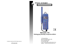
1
MONARCH INSTRUMENT
Instruction Manual
Monarch 314
Datalogging Humidity Temperature Meter
© Monarch Instrument 2002 all rights reserved
1071-8041-210
15 Columbia Drive
Amherst, NH 03031-2334 USA
Phone: (603) 883-3390
Fax: (603) 886-3300
E-mail: [email protected]
Website: www.monarchinstrument.com
Safeguards and Precautions
1.
Read and follow all instructions in this manual
carefully, and retain this manual for future reference.
2.
Do not use this instrument in any manner inconsistent
with these operating instructions or under any
conditions that exceed the environmental
specifications stated.
3.
Do not touch or manipulate the sensor.
4.
Do not expose the sensor to direct light. This may
cause false readings.
5.
Do not expose the sensor to static electricity.
6.
Making measurements of high or low temperature can
be dangerous. Keep the hand holding the temperature
probe well away from the object being measured.
7.
This instrument is not user serviceable. For technical
assistance, contact the sales organization from which
you purchased the product or Monarch
Instrument directly.
LIMITED WARRANTY
SELLER warrants hardware products to be free from any defect in materials or workmanship
for a period of one (1) year from date of shipment to BUYER. SELLER’s entire liability and
BUYER’s sole and exclusive remedy resulting from any defect in workmanship or material
in the hardware product covered by this limited warranty shall be limited to and fully
discharged by the SELLER’s option of replacement or repair of such item without charge.
The limited warranty provided in this clause is in lieu of all other warranties, expressed or
implied, arising by law or otherwise. ALL IMPLIED WARRANTIES OF MERCHANTABILITY
AND FITNESS FOR A PARTICULAR PURPOSE ARE EXCLUDED. This limited warranty
shall not be modified except by an arrangement signed by both parties specifically
referencing this clause.
SELLER warrants that any software supplied will operate in accordance with the
documentation or manual supplied therewith in all material respects when used in strict
compliance with such documentation or manual. Notwithstanding the foregoing, BUYER
acknowledges that, since software is complex and therefore may have defects, BUYER’s
sole and exclusive remedy for any such defects or breach of this warranty shall be to
require SELLER, within a reasonable period of time, to provide all reasonable programming
services to correct programming errors in the software. Except as provided above SELLER
MAKES AND BUYER RECEIVES FROM SELLER NO EXPRESS OR IMPLIED WARRANTIES
OF ANY KIND WITH RESPECT TO ALL OR ANY PORTION OF SOFTWARE AND BUYER
HEREBY AGREES AND ACKNOWLEDGES THAT IT ACCEPTS THE SOFTWARE IN ‘AS IS’
CONDITION. SELLER HEREBY EXPRESSLY EXCLUDES ANY IMPLIED WARRANTIES
OF MERCHANTABILITY OR FITNESS FOR A PARTICULAR PURPOSE WITH RESPECT TO
THE SOFTWARE. BUYER agrees that any specific right or remedy granted to BUYER
hereunder with respect to any breach or default by SELLER shall be in lieu of all other
rights and remedies otherwise available to BUYER at law or in equity as the result of such
breach or default, regardless of whether based on contract, tort, strict liability, or other
theory of liability.
IN NO EVENT SHALL SELLER BE LIABLE FOR ANY SPECIAL, INDIRECT, INCIDENTAL,
CONSEQUENTIAL, OR PUNITIVE LOSSES OR DAMAGES (INCLUDING, BUT NOT
LIMITED TO, LOSSES OR DAMAGES FOR ANY LOST PROFITS OR LOST DATA) AS THE
RESULT OF ANY BREACH OR DEFAULT BY SELLER WITH RESPECT TO THE HARDWARE
OR SOFTWARE, EVEN IF SELLER HAS BEEN ADVISED OR MADE AWARE OF THE
POSSIBILITY OF ANY SUCH LOSSES OR DAMAGES AND REGARDLESS OF WHETHER
THE CLAIM IS BASED ON CONTRACT, TORT, STRICT LIABILITY, OR OTHER THEORY OF
LIABILITY.
This limited warranty does not extend or apply to consumables (including, but not limited
to, lamps and batteries, if applicable) or equipment, instruments or accessories which are
warranted separately by the original manufacturer of these items.
MODEL 314 DATALOGGING HUMIDITY TEMPERATURE METER
DECLARATION OF CONFORMITY
Table of Contents
Section
Monarch Instrument
Page
Division of Monarch International Inc.
15 Columbia Drive, Amherst NH 03031 USA
1.0
Introduction .................................................................................................................1
declares that the product:
2.0
Specifications ............................................................................................................1
3.0
Symbol Definitions and Feature Locations ........................................2
4.0
Operating Instructions........................................................................................3
Name:
Model:
Humidity Temperature Meter
Monarch 314
4.1
4.2
4.3
4.4
4.5
4.6
4.7
4.8
4.9
4.10
4.11
4.12
4.13
to which this declaration relates is in conformity with the following standards:
EMC:
EN55011/1991
EN50081-1/1992
EN50082-1/1992 / IEC 801
and therefore conforms in accordance with 89/336/EEC-EMC Directive. The
testing of this product was performed by GesTek EMC Lab. in January of
2000. (Ref. No. 99C049E).
Preparation for Measurement .....................................................................................3
Power ............................................................................................................................3
Humidity and Temperature (T1) Measurement ..........................................................3
Selecting the Temperature Scale................................................................................3
Data-Hold Operation ....................................................................................................3
Clock Setup ..................................................................................................................3
Time Function...............................................................................................................3
Recording Interval Setup ............................................................................................4
Recording Data.............................................................................................................4
MAX/MIN Operation .....................................................................................................4
Auto Power Off.............................................................................................................4
Low Battery Condition.................................................................................................4
Digital Output ...............................................................................................................4
Appendix: Thermocouple Probe Specifications ..........................5
5.0
Calibration Procedure .........................................................................................5
5.1 Humidity Calibration....................................................................................................5
5.2 T1 Temperature Calibration.........................................................................................5
5.3 Notes on Humidity and Temperature Calibration .....................................................6
6.0
Setup TestLink (Humidity DataLogger) – RS232 Interface
Software .........................................................................................................................7
7.0
Running TestLink .....................................................................................................7
7.1 Open TestLink ..............................................................................................................7
7.2 Real Time Tabular and Real Time Graph ...................................................................7
7.3 DataLogger ...................................................................................................................8
2nd February 2000
Importer (Amherst, NH)
Alan Woolfson, VP Engineering
(Authorized Signature)
MODEL 314 DATALOGGING HUMIDITY TEMPERATURE METER
1.0
Introduction
This instrument is a dual channel, recording digital Humidity / Temperature meter providing
simultaneous display of ambient humidity and temperature on the first channel, and a wide
range temperature only measurement on the second channel. The first channel incorporates
a polymer capacitive humidity sensor and a semiconductor temperature sensor (T1) in a
detachable probe. The second channel employs a Type K thermocouple that complies with
the NIST and IEC584 temperature/voltage tables for Type K thermocouples. The instrument’s
internal memory can store up to 16312 records in any number of recording intervals. It is
equipped with a RS232 interface for bi-directional communication with a PC.
2.0
Specifications
Measurement Range:
Accuracy:
Humidity:
0% - 100%RH
Temperature: T1: -20°C - +60°C,
T2: -200°C - +1370°C,
Humidity:
±2.5% RH at 25°C
Temperature: T1: ±0.7°C, ±1.4°F
T2: See table below.
-4°F - +140°F
-328°F - +2498°F
at ( 23 ± 5°C )
Range
-200°C - 200°C
200°C - 400°C
400°C - 1370°C
-328°F - -200°F
-200°F - 2498°F
Accuracy
±(0.3% reading + 1°C)
±(0.5% reading + 1°C)
±(0.3% reading + 1°C)
±(0.5% reading + 2°F)
±(0.3% reading + 2°F)
Temperature Coefficient:
For ambient temperatures from 0°C -18°C and
28°C - 50°C, for each °C ambient below 18°C or
above 28°C add the following tolerance into the
accuracy spec.
0.01% of reading + 0.03°C
(0.01% of reading + 0.06°F)
Note:
The basic accuracy specification does not include the error of the probe. Please refer to the probe accuracy
specification for additional details.
Humidity:
0.1%RH
Temperature: T1: 0.1°C, 0.1°F
T2: -200°C - 200°C: 0.1°C;
200°C -1370°C:
1°C
-200°F - 200°F: 0.1°F;
beyond this range: 1°F
Sensor Inputs: Channel 1: Detachable probe with humidity and temperature (T1) sensors
Channel 2: Type K Thermocouple (T2)
Input Protection at Thermocouple Input (T2): 60V DC, or 24Vrms AC
Display:
Triple 4 Digit Display plus Indicators, see Section 3.0
75 seconds in slowly moving air
Response Time: Humidity:
Temperature: 40 seconds in slowly moving air (T1)
Digital Output: Bi-directional RS232. Software and Cable included
Power requirement: 9 Volt Battery, NEDA 1604 or JIS 006P or IEC6F22
Battery Life:
Approx. 100 hours with alkaline battery; Low battery indication
Operating Conditions:
x Operating Temperature and Humidity: 0°C - 50°C (32°F - 122°F); 0 - 90% RH
Non-condensing
x Storage Temperature and Humidity:
-10°C - 60°C (14°F - 140°F); 0 - 80% RH
Non-condensing
x Altitude up to 2000 meters (6500 feet)
Dimensions: Meter = 186×64×30 mm (7.3×2.5×1.2 inches)
Probe = 190 mm long×15 mm diameter (7.5×0.6 in)
Weight:
Approx. 320g (10.8 oz)
Accessories: Type K Wire Thermocouple Probe, Battery, Carrying Case, Humidity Probe
Holder, Instruction Manual, Software, RS232 cable
Option:
AC Adapter: 9VDC ±15%, 100mA; Plug Diameter: 3.5mm×1.35mm
Resolution:
1
Notes
Notes
MODEL 314 DATALOGGING HUMIDITY TEMPERATURE METER
Symbol Definitions and Feature Locations:
: Low battery indication. Battery voltage is not sufficient for proper operation.
: Indicates ‘Auto Power Off’ is enabled
: Indicates that the display data is being held
MAX
: The Maximum value is now being displayed
MIN
: The Minimum value is now being displayed
REC
: Indicates that the instrument is recording. When flashing, the memory is full.
Y
: Indicates year is displayed in the main window
K
: Thermocouple type indication
%RH
m-d
: Relative Humidity indication
: Indicates the value below is month and day
T1 T2 : Indicates which temperature channel is being displayed
h:m
: Indicates the value below is hour and minute
m:s
: Indicates the value below is minute and second
–
°C°F
: Negative temperature indication
: Centigrade or Fahrenheit indication
1
Feature Locations:
2
1)
2)
3)
3
T1
T2 ( K-TYPE )
4
5
8
CLOCK
INTV
7
REC
C
F
TEMP: 20 C
60 C
4 F
140 F
) 200 C
1370 C
328 F
2498 F
HUMIDITY: 0
100 %RH
9
RS-232
6
HOLD
CAL
SETUP
TIME
11
9V BATTERY
NEDA 1604 6F22 00
PLEASE READ
MANUAL FOR SAFE
DC9V
3.0
(
POWER-UP OPTIONS
REC
OPEN
4)
5)
6)
7)
8)
9)
10)
11)
12)
13)
14)
15)
Dust mask
Sensor probe
T2 channel, Type K thermocouple
probe input
LCD display
ON/OFF button
Time display button
Record control button
MAX MIN function control button
HOLD button
°C / °F control button
Type K offset calibration screw
Digital output connector (RS232)
AC power adapter connector
Tripod connector
Battery cabinet cover
2
MODEL 314 DATALOGGING HUMIDITY TEMPERATURE METER
4.0
Operating Instructions:
4.1 Preparation for Measurement
Measurement of ambient humidity and temperature (T1) may be made with the probe
clipped to the instrument or hand held remotely.
For measurement of a second temperature, plug a Type K thermocouple into the socket
marked T2, taking care to observe the polarity of the thermocouple pins.
4.2 Power
Press the
button to turn the thermometer ON or OFF.
When first powered on, the display will show how much memory
space is available for use.
Example: Display at right indicates 16,000 records of available
memory.
4.3 Humidity and Temperature (T1) Measurement
Place the humidity temperature probe in the environment to be measured. Be sure to
allow sufficient time for the sensors to respond to ambient conditions. This time will be
dependent on the amount of air circulation through the probe mask. (See Section 2.0:
Response Time.)
4.4 Selecting the Temperature Scale
When first turned on, the instrument defaults to reading in Celsius (°C). To display
readings in Fahrenheit (°F), press the °C / °F button. To return to readings in Celsius (°C),
again press the °C / °F button. The instrument remembers the scale setting when last
turned off and powers on in that setting the next time.
4.5 Data-Hold Function
The present reading is held on the display by pressing the HOLD button. Pressing the
HOLD button again releases the hold function and returns the instrument to
continuous reading.
In the HOLD mode, the MAX MIN, °C / °F and UREL buttons are disabled, as indicated
by two consecutive beeps when pressed.
4.6 Clock Setup
To set the real time clock:
MODEL 314 DATALOGGING HUMIDITY TEMPERATURE METER
7.3 DataLogger
Select DataLogger from the menu to load recorded data from the humidity meter. A
progress bar will show how many bytes should be loaded and how many bytes have
been received. When data is loaded successfully, three new windows appear as below.
Data Sets
Graph
Tabular
Data Sets Window – Displays how many data sets were loaded and the detail
information for each data set (start date, start time, recording rate and data length). Click
on any data set to choose the set for graph and tabular window.
For other operating instructions, please refer to the online help while executing
TestLink.
1. Press and hold the MAX MIN button and then power on
the meter.
2. Press TIME (clock).
3. Press REC (n) or °C/°F (p) to increase or decrease the number.
4. Press TIME to move to the next item. The adjusting order is:
year; month; day; hour; minute.
5. Press TIME again after the last setting to complete the process.
To abort during a setup process, press the
button.
4.7 Time Function
Once setup, pressing the TIME button displays time as follows: top of the LCD – year;
bottom left of the LCD - month and day; bottom right of the LCD - hour and minute. Press
the TIME button or any other button to exit this mode. This operation will not interrupt the
recording and MAX/MIN operation.
3
8
MODEL 314 DATALOGGING HUMIDITY TEMPERATURE METER
6.0
Setup TestLink
Software:
(Humidity DataLogger) - RS232 Interface
The TestLink package contains:
1. Two 3.5” diskettes
2. Custom designed RS232 cable for TestLink
System Requirements:
Windows 95, Windows 98 or Windows NT 4.0
Minimum Hardware Required:
x 486-100 MHz PC, 16 MB RAM
x At least 5 MB hard disk space available to install TestLink program
x Recommended display resolution is 800x600.
Install TestLink:
1. Close all other applications before installing TestLink software.
2. Insert setup diskette 1 in floppy disk drive.
3. Choose the Start button on the Taskbar and select Run.
4. Type a:\setup and choose OK to copy TestLink.exe (executable file) and Help file to your
hard disk (default is c:\program files\testlink).
7.0
Running TestLink
7.1 Open TestLink
Select TestLink from Start of Windows. Your display should appear as below.
Menu and Tool Bar
Real Time Data Sampling
Rate
Real Time Graph
Bi-direction Control
Panel
Real Time Tabular
7.2 Real Time Tabular Data and Real Time Graph
Select Run from the menu or press
from the tool bar to begin real time data
collection from the humidity meter.
To change the data interval, edit the sampling rate from the box on the right hand side of
tool bar (see figure above).
MODEL 314 DATALOGGING HUMIDITY TEMPERATURE METER
4.8 Recording Interval Setup
To set the recording interval:
1. Press and hold the MAX MIN button and then power on
the meter.
2. Press HOLD (interval).
3. Press REC (n) or °C/°F (p) to increase or decrease the number.
4. Press HOLD to advance to the next item.
5. Press HOLD again after the last setting to complete the process.
To abort during a setup process, press the
button.
4.8 Recording Data
Each momentary press of the REC button will alternately start
and stop recording. To clear the memory, power off the meter,
press and hold the REC button followed by the
button,
holding both on simultaneously for at least 2 seconds. Then
release both buttons. The display will show "CLR" (as shown to
the right) indicating that the memory has been cleared.
4.10 MAX/MIN Operation
Press the MAX MIN button to enter the MAX/MIN mode. In this mode, both the maximum
and minimum values are simultaneously retained in memory and updated with every new
data sample. The instrument first enters the MAX mode, and the MAX symbol and value
are both displayed. Pressing MAX MIN again advances the display to the MIN symbol
and value. The next press of the MAX MIN button will cause both the MAX and MIN
symbols to flash. This indicates that the maximum and minimum values have been
updated in memory and the displayed reading is the present value. Each successive
press of the MAX MIN button circulates the display mode among these options. To exit
the MAX/MIN mode, press and hold the MAX MIN button for two seconds.
In the MAX/MIN mode, the °C/°F button is disabled, as indicated by two consecutive
beeps if pressed.
4.11 Auto Power Off
By default, the instrument powers on in the ‘Auto Power Off’ mode and will automatically
shut off 30 minutes after the last key operation or RS232 communication.
To disable this feature, press and hold the HOLD button and then power on the meter.
Two successive beeps will indicate that ‘Auto Power Off’ is disabled, and the
will not
be displayed.
4.12 Low Battery Condition
When the battery voltage is at or below the minimum for proper operation, the
symbol will show on the LCD indicating that the battery must be replaced.
4.13 Digital Output
The Digital Output is a 9600 bps N 81 serial interface.
RX is a 5V normally high input port.
TX is a 5V normally high output port.
WARNING!
1.
2.
3.
7
Do not touch or manipulate the sensor.
Do not expose the sensor to direct light. This may cause false readings.
Do not expose the sensor to static electricity.
4
MODEL 314 DATALOGGING HUMIDITY TEMPERATURE METER
Appendix: Thermocouple Probe Specifications
Model
Range
Tolerances
Description
TP-K01
Wire probe
-50°C to 200°C
-58°F to 392°F
±2.2°C or ±0.75%
±3.6°F or ±0.75%
Teflon insulation. Maximum insulation
temperature: 260°C (500°F)
TP-K01:
Probe for general condition measurements, especially
for complex and hard to reach places.
5.0
Calibration Procedure
5.1 Humidity Calibration
1. Turn the unit off. Press and hold the MAX MIN, HOLD and REC buttons. While
these three buttons are pressed, turn the power on. Release these buttons and all
the segments on the display will flash.
2. Within 3 seconds of releasing these buttons, press the °C/°F and TIME buttons
simultaneously to enter the calibration mode, or the instrument will revert to the
normal operating mode.
3. Upon entering the calibration mode, the humidity reading will flash, and ‘CAL1’ will
appear on the second display.
4. Insert the humidity probe into the standard humidity cavity of 32.8% RH@25°C.
Allow the system to stabilize for 20 minutes, and then press the MAX MIN button to
create the calibration data. If the instrument recognizes the value is out of tolerance,
it will sound 2 beeps and remain in the ‘CAL1’ mode. If the instrument recognizes
the value is within tolerance, new calibration data is created and the instrument will
advance into the ‘CAL2’ mode, as indicated on the second display.
5. Insert the humidity probe into the standard humidity cavity of 75.3% RH@25°C.
Again allow the system to stabilize for 20 minutes, and then press the MAX MIN
button to create the calibration data. If the instrument recognizes the value is out of
tolerance, it will sound 2 beeps and remain in the ‘CAL2’ mode. If the instrument
recognizes the value is within tolerance, new calibration data will be written into the
memory and the calibration is complete.
5.2 T1 Temperature Calibration
1. Turn the unit off. Press and hold the MAX MIN, HOLD and REC buttons. While
these three buttons are pressed, turn the power on. Release these buttons and all
the segments on the display will flash.
2. Within 3 seconds of releasing these buttons, press the °C/°F and HOLD buttons
simultaneously to enter the calibration mode, or the instrument will revert to normal
operating mode.
3. Upon entering the calibration mode, the temperature reading will flash and ‘CAL1’
will appear on the second display.
4. Insert the probe into a temperature-controlled chamber at 0°C (32°F) and allow the
system to stabilize for 20 minutes. Press the MAX MIN button to create the
calibration data. If the instrument recognizes the value is out of tolerance, it will
sound 2 beeps and remain in the ‘CAL1’ mode. If the instrument recognizes the
value is within tolerance, new calibration data is created and the instrument will
advance into the ‘CAL2’ mode, as indicated on the second display.
5. Insert the probe into a temperature-controlled chamber at 40°C (104°F) and again
allow the system to stabilize for 20 minutes. Press the MAX MIN button to create
the calibration data. If the instrument recognizes the value is out of tolerance, it will
sound 2 beeps and remain in the ‘CAL2’ mode. If the instrument recognizes the
value is within tolerance, new calibration data will be written into the memory and
the calibration is complete.
5
MODEL 314 DATALOGGING HUMIDITY TEMPERATURE METER
5.3 Notes on Humidity and Temperature Calibrations
1. While performing the humidity calibration, the environment should be maintained at
stable conditions (i.e. constant temperature and constant humidity) to optimize the
accuracy.
2. During either calibration, pressing the
button at any time will return the
instrument to the normal operating mode, and no calibration data will be changed.
3. To restore factory default calibration values, press the HOLD and REC buttons
simultaneously at any time while in the calibration mode.
4. Whenever the probe is inserted into a standard humidity cavity or
temperature-controlled chamber, always allow at least 20 minutes to ensure
ambient conditions have stabilized.
5. Always begin the humidity calibration process with the 32.8% RH@25°C standard
cavity and the temperature calibration process with the 0°C (32°F)
temperature-controlled chamber. For maximum efficiency, insert the probe into the
conditioned environment 20 minutes before applying power to the instrument and
starting the calibration process.
6. During the calibration, all displayed readings are based on pre-process
calibration data.
7. The ‘Auto Power Off’ function is disabled during calibration, but is automatically
restored upon completion.
8. During the calibration, the temperature is fixed on the °F scale and it is
not selectable.
6