1
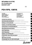
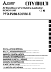
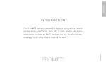
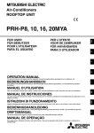
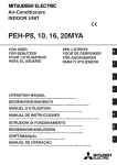
Air-Conditioners INDOOR UNIT Back to Index OPERATION MANUAL RU NL I E F D GB PFD-P250 • 500VM-A BEDIENUNGSHANDBUCH Zum sicheren und einwandfreien Gebrauch der Klimaanlage dieses Bedienungshandbuch vor Inbetriebnahme gründlich durchlesen. GR For safe and correct use, please read this operation manual thoroughly before operating the air-conditioner unit. Pour une utilisation correcte sans risques, veuillez lire le manuel d’utilisation en entier avant de vous servir du climatiseur. MANUAL DE INSTRUCCIONES RU MANUEL D’UTILISATION ISTRUZIONI DI FUNZIONAMENTO Leggere attentamente questi istruzioni di funzionamento prima di avviare l’unità, per un uso corretto e sicuro della stessa. BEDIENINGSHANDLEIDING Voor een veilig en juist gebruik moet u deze bedieningshandleiding grondig doorlezen voordat u de airconditioner gebruikt. РУКОВОДСТВО ПО ЭКСПЛУАТАЦИИ Для обеспечения правильного и безопасного использования следует ознакомиться с инструкциями, указанными в данном руководстве по эксплуатации, тщательным образом до того, как приступать к использованию кондиционера. TR Lea este manual de instrucciones hasta el final antes de poner en marcha la unidad de aire acondicionado para garantizar un uso seguro y correcto. I Remote controller-Button Fernbedienungs-Taste Touche Commande à distance GB D F E NL RU Bottone dell’unità del comando a distanza Controlador remoto-Botón Knop afstandbediening Кнопка контроллера ДУ 1 2 3 4 CENTRALLY CONTROLLED ON 1Hr. OFF ˚C CLOCK CHECK ˚C STAND BY DEFROST 1 ERROR CODE TEMP. NOT AVAILABLE FILTER CHECK MODE TEST RUN FUNCTION ON/OFF B 2 FILTER 3 CHECK TEST PAR-20MAA A 0 TIMER SET C Pulsante [Regolazione della temperatura ambiente] Pulsante [Timer/continuo] Pulsante [Selezione modalità di funzionamento] Pulsante [Selezione ora] Pulsante [Impostazione dell’ora] 5 Pulsante [Regolazione deflettore] 6 Pulsante [Regolazione della velocità di ventilazione] 7 Pulsante [Regolazione della direzione di soffiaggio verso l’alto/il basso] 8 Pulsante [Ventilazione] 9 Pulsante [Controllo/Incorporata] 0 Pulsante [Prova di funzionamento] A Pulsante [Filtro] B Pulsante [ACCENSIONE/SPEGNIMENTO] C Posizione temperatura ambiente incorporata • • 4 5 6 87 9 1 2 3 4 5 6 7 8 9 0 A B C • • 1 2 3 4 5 6 7 8 9 0 A B C • • [Room temperature adjustment] Button [Timer/continuous] Button [Selecting operation] Button [Time selection] Button [Time-setting] Button [Louver] Button [Fan speed adjustment] Button [Up/down airflow direction] Button [Ventilation] Button [Checking/built-in] Button [Test run] Button [Filter] Button [ON/OFF] Button Position of built-in room temperature 1 Botón [Ajuste de la temperatura de la habitación] 2 Botón [Temporizador/continuo] 3 Botón [Selección del modo de funcionamiento] 4 Botón [Selección de la hora] Botón [Determinación de la hora] 5 Botón [Persiana] 6 Botón [Ajuste de la velocidad del ventilador] 7 Botón [Dirección de la corriente ascendente/descendente de aire] 8 Botón [Ventilación] 9 Botón [Comprobación/Incorporada] 0 Botón [Prueba de funcionamiento] A Botón [Filtro] B Botón [ON/OFF] C Posición de temperatura ambiente incorporada Never expose the remote controller to direct sunlight. Doing so can result in the erroneous measurement of room temperature. Never place any obstacle around the lower right-hand section of the remote controller. Doing so can result in the erroneous measurement of room temperature. • Raumtemperatur-Tasten Zeitschalter-/Dauerbetrieb-Taste Betriebsart-Taste Zeitumschalt-Taste Zeiteinstell-Tasten Klappen-Taste Luftstromgeschwindigkeit-Taste Vertikale luftstromrichtung-Tasten Belüftung-Tasten Überprüfen/Eingebauten-Tasten Testlauf-Tasten Filter-Taste Betrieb-/Stop-Taste Position der eingebauten Raumtemperatur 1 2 3 4 Die Fernbedienung nicht direkter Sonneneinstrahlung aussetzen. Die Raumtemperatur wird sonst nicht korrekt gemessen. Den rechten unteren Teil der Fernbedienung nicht blockieren. Die Raumtemperatur wird sonst nicht korrekt gemessen. • • 5 6 7 8 9 0 A B C • 1 Touche de [réglage de la température de la pièce] 2 Touche de [fonctionnement continu/minuterie] 3 Touche de [sélection du mode de fonctionnement] 4 Touche de [sélection de l’heure] Touche de [réglage de l’heure] 5 Touche de [pivotement] 6 Touche de [réglage de la vitesse du ventilateur] 7 Touche de [sens de la soufflerie vers le haut/vers le bas] 8 Touche [Ventilation] 9 Touche [Vérification/Intégré] 0 Touche [Essai de fonctionnement] A Touche de [filtre] B Touche [ON/OFF] C Position du capteur intégré de la température de la pièce 1 2 3 4 • • • Non esporre mai il comando a distanza alla luce diretta del sole, in quanto questo può alterare la corretta rilevazione della temperatura ambiente. Non porre alcun ostacolo attorno alla sezione inferiore destra del comando a distanza, in quanto questo può alterare la corretta rilevazione della temperatura ambiente. Ne jamais laisser la commande à distance en plein soleil sinon les données de température ambiante risquent d’être erronées. Ne jamais placer d’obstacle devant la partie inférieure droite de la commande à distance sinon la lecture des températures ne sera pas correcte. 2 5 6 7 8 9 0 A B C • Nunca exponga el mando a distancia a la luz directa del sol. Si lo hace, se producirá una lectura errónea de la temperatura de la habitación. Nunca ponga ningún obstáculo alrededor de la sección inferior derecha del mando a distancia. Si lo hace, se producirá una lectura errónea de la temperatura de la habitación. [Aanpassen kamertemperatuur] Knop [Timer/continu] Knop [Standselectie] Knop [Tijdselectie] Knop [Tijdinstellings] Knop [Ventilatie-jaloezie] Knop [Aanpassen van de ventilatorsnelheid] Knop [Blaasrichting naar boven/ naar beneden] Knop Knop [Ventilatie] Knop [Controle/Ingebouwde] Knop [Proefdraaien] [Filter] Knop [ON/OFF (AAN/UIT)] Knop Plaats van ingebouwde kamertemperatuursensor Laat de afstandsbediening nooit in direct zonlicht liggen. Als u dit toch doet kan het zijn dat de kamertemperatuur onjuist gemeten wordt. Zet of hang nooit iets in de buurt van het gedeelte rechtsonder op de afstandsbediening. Als u dit toch doet kan het zijn dat de kamertemperatuur onjuist gemeten wordt. Кнопка [Регулирование температуры в помещении] Кнопка [Таймер/постоянно] Кнопка [Выбор операции] Кнопка [Выбор времени] Кнопка [Настройка времени] Кнопка [жалюзи] Кнопка [Регулировки скорости вентилятора] Кнопка [Направления потока воздуха вверх/вниз] Кнопка [Вентиляция] Кнопка [Проверка/встроенного датчика] Кнопка [Тестовый прогон] Кнопка [Фильтр] Кнопка [ВКЛ./ВЫКЛ.] Позиция встроенного датчика температуры помещения Никогда не подвергайте пульт дистанционного управления воздействию прямых солнечных лучей. Это может привести к неправильным замерениям температуры в помещении. Никогда не помещайте какое-либо препятствие перед нижней правой секцией пульта дистанционного управления. Это может привести к неправильному замерению температуры в помещении. I GB D F Remote controller-Button Fernbedienungs-Taste Affichage Commande à distance B A C Power Operating Check PFD-P250VM-A D A E NL RU B C Power Operating Check Failure F G No.1 Failure No.2 Failure PFD-P500VM-A Local A Spia alimentazione B Spia funzionamento C Spia di controllo D Spia guasto E Commutatore Normal/Local F Spia guasto n.1 G Spia guasto n.2 * Se il funzionamento Local è disponibile in fase di manutenzione, impostare il commutatore “Normal/Local” su “Local”. Quindi si illuminerà la spia “Check”. Local TEST RUN E TEMP. ON/OFF TEST RUN E TEMP. FILTER CHECK TEST TIMER SET Normal ON/OFF FILTER CHECK TEST PAR-20MAA Bottone dell’unità del comando a distanza Controlador remoto-Botón Display afstandbediening Кнопка контроллера ДУ PAR-20MAA TIMER SET Normal A Power display lamp A Indicador de alimentación B Operation display lamp B Indicador de funcionamiento C Check display lamp C Indicador de comprobación D Fault display lamp D Indicador de avería E Normal / Local switch E Interruptor Normal / Local F No.1 Fault display lamp F Indicador de avería N° 1 G No.2 Fault display lamp G Indicador de avería N° 2 * When Local operation is available at maintenance, please set “Normal / Local” switch to “Local”. Then “Check” lamp will be lit. * Cuando esté disponible el funcionamiento Local durante el mantenimiento, ajuste el interruptor “Normal / Local” a “Local”. A continuación, se encenderá el indicador “Check”. A Netzstromkontrolllampe A Voedingslampje B Betriebskontrolllampe B Bedieningslampje C Prüfkontrolllampe C Controlelampje D Fehleranzeigelampe D Storingslampje E Normal-/Lokalschalter E Schakelaar “Normal/Local” F Fehleranzeigelampe Nr. 1 F Storingslampje 1 G Fehleranzeigelampe Nr. 2 G Storingslampje 2 * Wenn bei Wartungsarbeiten Lokalbetrieb verfügbar ist, bitte den Normal-/Lokalschalter auf “Lokal” einstellen, danach leuchtet die “Check” (Prüf)-Lampe. * Wanneer bij onderhoud lokale bediening mogelijk is, stelt u de schakelaar “Normal/Local” op Local. Het controlelampje zal gaan branden. A Témoin d’alimentation A Индикатор “Power” (Питание) B Témoin de fonctionnement B Индикатор “Operation” (Работа) C Témoin de contrôle C Индикатор “Check” (Проверка) D Témoin de panne D Индикатор “Fault” (Неисправность) E Commutateur normal / local E Переключатель “Normal/Local” (Нормальный/Местный) F Témoin d’erreur n°1 F Индикатор “No.1 Fault” (Неисправность N° 1) G Témoin d’erreur n°2 G Индикатор “No.2 Fault” (Неисправность N° 2) * Si le fonctionnement en mode local est disponible pour la maintenance, placer le commutateur “Normal / Local” sur “Local”. Le témoin “Check” s’allume. * Если доступен режим Local, то, пожалуйста, переведите переключатель “Normal/Local” в положение “Local”. Затем загорится индикатор “Check”. 3 [Fig. A] [Fig. B-1] B A Parallel Pulley Cast iron pulley K (minutes) 10 or less Remarks Equivalent to 3 mm displacement per meter. K K K D K K E SWC C SWC [Fig. B-2] A Address board B Control board C Address board D Option: Inlet temperature control E Standard: Outlet temperature control A Deflection load (W) 3 - 4kg = 5mm 4 Contents 1. Safety precautions ...................................................................................... 1.1. Installation ................................................................................. 1.2. During operation ........................................................................ 1.3. Disposing of the unit .................................................................. 2. Names and functions of various parts ........................................................ 3. How to operate ........................................................................................... 3.1. ON/OFF ..................................................................................... 3.2. Selecting operation .................................................................... 3.3. Room temperature adjustment .................................................. 3.4. Time setting ............................................................................... 3.5. Timer setting .............................................................................. 3.6. Selecting Normal and Check Operation ................................... 3.7. Fault Reset ............................................................................... 3.8. Others ........................................................................................ 5 5 5 6 6 6 6 7 7 7 7 8 8 8 4. 5. 6. 7. 8. 9. 10. 11. 12. 13. 14. 15. 16. 17. “Failure” Display Lamps .............................................................................. 8 Control of Indoor Unit Inlet or Outlet Temperature ...................................... 8 The smart way to use ................................................................................. 8 Caring for the unit ....................................................................................... 8 Troubleshooting ........................................................................................... 9 Installation, transferring works, and checking ............................................. 9 Checking Drainage ................................................................................... 10 Checking V Belts ....................................................................................... 10 Cleaning the Indoor Unit Heat Exchanger ................................................ 10 Greasing the Fan Bearings ....................................................................... 10 When the Unit is to be out of Use for a Long Time ................................... 10 Periodic Checks ........................................................................................ 11 Specifications ............................................................................................ 12 Warranty and Servicing ............................................................................ 12 1. Safety precautions 2) Indoor unit Symbols used in the text 3) Remote controller Caution: Describes precautions that should be observed to prevent damage to the unit. Symbols used in the illustrations : Indicates an action that must be avoided. Warning: The remote controller should be installed in such a way that children cannot play with it. 4) Drain hose Caution: : Indicates that important instructions must be followed. : Indicates a part which must be grounded. : Indicates that caution should be taken with rotating parts. (This symbol is D Warning: The indoor unit should be securely installed. If the unit is loosely mounted, it may fall, causing injury. F Warning: Describes precautions that should be observed avoid the risk of injury or death to the user. GB Caution: The outdoor unit should be installed in a location where air and noise emitted by the unit will not disturb the neighbours. E s Before operating the unit, make sure you read all the “Safety precautions”. s “Safety precautions” lists important points about safety. Please be sure to follow them. Make sure that the drain hose is installed so that drainage can go ahead smoothly. Incorrect installation may result in water leakage, causing damage to furniture. displayed on the main unit label.) <Color: yellow> s After you have read this manual, keep it and the Installation Manual in a Warning: • • • • • • The unit should not be installed by the user. Ask the dealer or an authorized company to install the unit. If the unit is installed improperly, water leakage, electric shock or fire may result. Use only accessories authorized by Mitsubishi Electric and ask your dealer or an authorized company to install them. If accessories are installed improperly, water leakage, electric shock or fire may result. The Installation Manual details the suggested installation method. Any structural alteration necessary for installation must comply with local building code requirements. Never repair the unit or transfer it to another site by yourself. If repair is performed improperly, water leakage, electric shock or fire may result. If you need to have the unit repaired or moved, consult your dealer. The appliance is not intended for use by young children or infirm persons without supervision. Young children should be supervised to ensure that they do not play with the appliance. 6) Grounding Caution: • • Caution: • • • • Warning: • The outdoor unit must be installed on a stable, level surface, in a place where there is no accumulation of snow, leaves or rubbish. Do not stand on, or place any items on the unit. You may fall down or the item may fall, causing injury. The unit must be properly grounded. Never connect the grounding wire to a gas pipe, water pipe, lightning conductor or telephone grounding wire. If the unit is not grounded properly, electric shock may result. Check frequently that the ground wire from the outdoor unit is properly connected to both the unit’s ground terminal and the grounding electrode. 1.2. During operation 1) Outdoor unit • P safe place for easy reference whenever a question arises. If the unit is going to be operated by another person, make sure that this manual is given to him or her. NL • • Make sure that the unit is powered by a dedicated supply. Other appliances connected to the same supply could cause an overload. Make sure that there is a main power switch. Be sure to adhere to the unit’s voltage and fuse or circuit breaker ratings. Never use a piece of wire or a fuse with a higher rating than the one specified. • GR 1.1. Installation Warning: • RU Warning: Carefully read the labels affixed to the main unit. I 5) Power line, fuse or circuit breaker <Color: yellow> Do not use any sharp object to push the buttons, as this may damage the remote controller. Do not twist or tug on the remote controller cord as this may damage the remote controller and cause malfunction. Never remove the upper case of the remote controller. It is dangerous to remove the upper case of the remote controller and touch the printed circuit boards inside. Doing so can result in fire and failure. Never wipe the remote controller with benzene, thinner, chemical rags, etc. Doing so can result in discoloration and failure. To remove heavy stains, soak a cloth in neutral detergent mixed with water, wring it out thoroughly, wipe the stains off, and wipe again with a dry cloth. Never block or cover the indoor or outdoor unit’s intakes or outlets. Tall items of furniture underneath the indoor unit, or bulky items such as large boxes placed close to the outdoor unit will reduce the unit’s efficiency. 5 TR : Beware of electric shock. (This symbol is displayed on the main unit label.) • Ensure that the drain trap is properly water-sealed. - If the drain trap is modified, or is not water-sealed, the trap will not function and a water leak may occur. Inject water into the hose during the periodic check (six-monthly) to check water-sealing. Warning: • • • Do not splash water over the unit and do not touch the unit with wet hands. An electric shock may result. Do not spray combustible gas close to the unit. Fire may result. Do not place a gas heater or any other open-flame appliance where it will be exposed to the air discharged from the unit. Incomplete combustion may result. In case of failure Warning: • • • • Warning: • • GB • • • D • Do not remove the front panel or the fan guard from the outdoor unit when it is running. You could be injured if you touch rotating, hot or highvoltage parts. Never insert fingers, sticks etc. into the intakes or outlets, otherwise injury may result, since the fan inside the unit rotates at high speed. Exercise particular care when children are present. If you detect odd smells, stop using the unit, turn off the power switch and consult your dealer. Otherwise, a breakdown, electric shock or fire may result. When you notice exceptionally abnormal noise or vibration, stop operation, turn off the power switch, and contact your dealer. Do not over-cool. The most suitable inside temperature is one that is within 5 °C of the outside temperature. Do not leave handicapped people or infants sitting or standing in the path of the airflow from the unit. This could cause health problems. When the unit is not to be used for a long time • • • F Do not direct the airflow at plants or caged pets. Ventilate the room frequently. If the unit is operated continuously in a closed room for a long period of time, the air will become stale. If the unit is not to be used for a long time due to a seasonal change, etc., run it for 4 - 5 hours with the air blowing until the inside is completely dry. Failing to do so can result in the growth of unhygienic, unhealthy mold in scattered areas throughout the room. When it is not to be used for an extended time, keep the [power supply] turned OFF. If the power supply is kept on, several watts or several tens of watts will be wasted. Also, the accumulation of dust, etc., can result in fire. Keep the power switched ON for more than 12 hours before starting operation. Do not turn the power supply OFF during seasons of heavy use. Doing so can result in failure. 1.3. Disposing of the unit Caution: • • Never remodel the unit. Consult your dealer for any repair service. Improper repair work can result in water leakage, electric shock, fire, etc. If the remote controller displays an error indication, the unit does not run, or there is any abnormality, stop operation and contact your dealer. Leaving the unit as it is under such conditions can result in fire or failure. If the power breaker is frequently activated, get in touch with your dealer. Leaving it as it is can result in fire or failure. If the refrigeration gas blows out or leaks, stop the operation of the unit, thoroughly ventilate the room, and contact your dealer. Leaving the unit as it is can result in accidents due to oxygen deficiency. Warning: When you need to dispose of the unit, consult your dealer. If pipes are removed incorrectly, refrigerant (fluorocarbon gas) may blow out and come into contact with your skin, causing injury. Releasing refrigerant into the atmosphere also damages the environment. E 2. Names and functions of various parts Attachment and detachment of filter Caution: I • • In removing the filter, precautions must be taken to protect your eyes from dust. Also, if you have to climb up on a stool to do the job, be careful not to fall. Turn off the power supply when the filter is changed. NL 3. How to operate The above does not apply to the models that simultaneously run both the cooling operation and heating operation. A P Local • The outdoor units stop when all the indoor units connected to the counterpart outdoor units stop. • During heating operation, even if the indoor unit is set to operation while the outdoor unit is in defrosting operation, operation starts after the defrosting operation of the outdoor unit has ended. C E C TEST RUN GR TEMP. ON/OFF 1 B FILTER 3 CHECK TEST Normal 2 PAR-20MAA TIMER SET Start an operation 1. Press the B [ON/OFF] button Operation lamp V lights up and operation starts. RU Stop an operation 4 6 87 Before starting operation TR 3.1. ON/OFF • • Start running after the “H0” display has disappeared. The “H0” display briefly appears on the room temperature display (max. 3 minutes) when the power is turned on and after a power failure. This does not indicate any failure of the unit. The operation modes of the indoor units’ cooling operation, dry operation, and heating operation are different from those of the outdoor units. When the operation is started with cooling/dry (heating) and other indoor units connected to the counterpart outdoor units are already running in the same operation mode, the remote control displays “ ” or “ ” (“ ”) mode. However, the operation comes to stop, and you cannot get a desired mode. When this occurs, you will be notified by the “ ” or “ ” (“ ”) display that flashes in the liquid crystal display of the remote controller. Set to the operation mode of other indoor unit by the operation switch button. 6 1. Press the B [ON/OFF] button again Operation lamp goes off and operation stops. • Once the buttons have been set, pressing of the [ON/OFF] button only can repeat the same operation thereafter. • During operation, the operation lamp above the [ON/OFF] button lights up. Caution: Even if the operation button is pressed immediately after the operation is once stopped, operation is not restarted for about 3 minutes. This function protects the machine. It automatically starts operation after the lapse of approximately 3 minutes. 3.2. Selecting operation Caution: When the current time is not yet set, the “CLOCK (current time)” display flashes, disabling the setting of timer operation. When selecting operation 1. Press the 3 [selecting operation] button Consecutive press of the selecting operation button switches the operation over to E “ ,” “ ,” “ ,” (“ ”), and (“ ”). For the contents of operation, check the display. For cooling Press the 3 [selecting operation] button and bring up the “ ” display. 2. Set the current time by pressing the 4 • While the A “CLOCK” time is displayed, press the time setting 4 buttons and set the time. • The setting advances one minute every time the 4 once, and retrogresses one minute every time the 4 once. • Dry operation cannot be carried out at a room temperature of less than 18 °C. About 10 seconds after the button operation has been completed, the C “current time” and A “CLOCK” displays disappear. • Remote controller is equipped with a simplified clock with a precision of about + or - one minute per month. The time must be readjusted (reset) every time the unit is subjected to a power stop of the unit or a power failure. • Caution: Never expose your body directly to cool air for a long time. Excessive exposure to cool air is bad for your health, and should therefore be avoided. Dry operation The dry is a microcomputer-controlled dehumidifying operation which controls excessive air-cooling according to the room temperature of your choice. (Not usable for heating.) 1. Until reaching room temperature of your choice The compressor and indoor fan function is linked motion according to the change of the room temperature and automatically repeat ON/OFF. 2. When reaching room temperature of your choice Both the compressor and indoor fan stop. When stop continues for 10 minutes, the compressor and indoor fan are operated for 3 minutes to keep the humidity low. • If the timer is set, the unit starts (stops) at the set time, and the time mode is terminated. • When you wish to confirm the starting and ending time, press the 4 [time selection] button while C “ ” is displayed. Function of timer On-timer Set the on-timer for the time the working day begins in your company. When the set start time arrives, the unit starts operation. Off-timer Use the off-timer as a reminder to turn off the unit. When the set end-work time arrives, the unit stops operation. There are three methods for using the timer. 1. ON/OFF Timer When setting both starting and ending time 2. On-timer When only setting the starting time (Ending time is set to “ - - : - - ”) 3. Off-timer When only setting the ending time (Starting time is set to “ - - : - - ”) I When the unit is used together with burners, thoroughly ventilate the area. Insufficient ventilation can result in accidents due to oxygen deficiency. Never place a burner at a place where it is exposed to the airflow from the unit. Doing so can result in imperfect combustion of the burner. The microcomputer functions in the following cases: The fan is not moving at the set speed. - In some models, the system switches over to faint airflow when the temperature of the room reaches the set temperature. In other cases, it stops to prevent any cool air from escaping during the defrosting operation. Display example of timer setting ON OFF NL Caution: • • 3.5. Timer setting D The temperature of the room cannot be set by fan operation. F The fan operation functions to circulate the air in the room. • E • ” display. GB Caution: Press the 3 [selecting operation] button and bring up the “ • button is pressed button is pressed • For fan • / When respective 4 / buttons are pressed continuously, the time display goes fast forward. It advances in the order of 1 minute unit - 10 minute unit - one hour unit. Press the 3 [selecting operation] button and bring up the “ ” display. The indoor fan turns to the low-speed operation, disabling the change of fan speed. button The time cannot be set while the C “timer on” is displayed. For dry • or • ON OFF The example shows a timer set for operation start at 8:00 and end at 17:00. Indoor temperature can be set within the following range. Cooling/dry: 14 - 30 °C • It is impossible to set the room temperature by the air-blow operation. * The range of room temperature display is 8 - 39 °C. Outside this range, the display flashes either 8 - 39 °C to inform you if the room temperature is lower or higher than the displayed temperature. 3.4. Time setting • Set the current time after turning ON the power of the unit or after restoration from a power failure. • It can be set regardless of the operation of the indoor unit. • During the time operation, the time-setting button becomes void, disabling time setting. 1. Press the 4 [time selection] button and bring up the A “current time” display Every time it is pressed, the display changes. “current time” ON “timer start time” CLOCK OFF “timer end time” • (no display) 3. Press the 4 ( ) button of the 4 [time selection] and set the starting time When using it as an off-timer, set the starting time to “ - - : - - ”. The “ - - : - - ” is displayed next to 23:50. 4. Press the 4 [time selection] button and bring up the A “Timer end time” display 5. Press the 4 ( ) button of the [time switch] and set the ending time When using it as an on-timer, set the ending time to “ - - : - - ”. The “ - - : - - ” is displayed next to 23:50. 6. Press the 2 [timer/continuous] button and bring up the C “ Bringing up the C “ ” display completes the setting. ” display Every time the 4 ( ) button of the 4 [timer selection] is pressed once, it advances (or retrogresses) by 10 minutes. If the button is pressed continuously, it advances (or retrogresses) continuously. First set the hour digit and then set the minute digit. When the ON/OFF timer mode is set, you can run (on-timer) or stop (off-timer) operation by pressing the B [ON/OFF] button even when there is remaining time. Release Press the 2 [timer/continuous] button and disappear the “ ” display. 7 GR • 2. Press the 4 [time selection] button and bring up the A “Timer start time” display RU Press the 1 [room temperature adjustment] button and set the room temperature of your choice. Pressing or once changes the setting by 1 °C. If the pressing is continued, the setting continues to change by 1 °C. 1. Press the 2 [timer/continuous] button and bring up the C no display TR To change room temperature P 3.3. Room temperature adjustment Selecting Normal and Local Operation • Selecting Local operation Set the Normal/Local switch C to local. Start and stop is only possible with the remote controller (remote ON/OFF input disabled) when Local is selected, and faults occurring during checks are not displayed with remote output. • 3.6. 3.7. • • Fault Reset Reset when a fault display lamp is lit Press the ON/OFF button B. The unit stops and the fault is reset. * When repairs by the retailer or a specialist technician are complete, ensure that the unit is safe, and reset. The customer should not engage in repairs. • The unit cannot be stopped in the Normal mode. Select the Local operation mode and press the switch on the remote controller. Note that if the SW 1 - 10 on the indoor unit control board are ON (ie remote ON/OFF input not used) ON/OFF is also possible from the remote controller in the Normal mode. 3.8. Others CENTRALLY CONTROLLED Caution: GB Remote ON/OFF input and ON/OFF from the central controller (optional) are disabled in the Local operation mode. See the central controller users manual for details of ON/OFF from the central controller (optional) and input of temperature settings. Selecting ON/OFF from the remote controller requires a few seconds. This is not a fault. Following reset after a power failure, the unit begins operation again automatically, and ‘HO’ appears on the MA remote controller display after an interval of approximately 15 seconds. The MA remote controller cannot be used during this interval. Turn power OFF with the earth leakage breaker to stop the unit in an emergency. : Displayed when control is executed by a separately sold centralized control unit, etc. : This displays indication when some abnormality occurs in the unit. CHECK NOT AVAILABLE : When a button is pressed for any function which the indoor unit cannot perform, this display flashes concurrently with the display of that function. 4. “Failure” Display Lamps D PFD-P250VM-A Power Operating Check Failure * If both the “Operating” and “Failure” lamps are lit, either a fault has developed in the unit and it has stopped operating, or it is operating in the emergency mode. Note the unit number and error code appearing on the panel, and contact your serviceman. * A refrigerant system is operating normally if the associated fault display lamps are extinguished. The diagram at left shows an example of a fault in a refrigerant system. F PFD-P500VM-A NL I E Power Operating Check No.1 Failure No.2 Failure 5. Control of Indoor Unit Inlet or Outlet Temperature Either of the above methods of temperature control may be selected with this model. The method of control is selected with the switch SWC on the address board inside the indoor unit controller shown in the Fig. A. When the unit is shipped from the factory it is set to outlet temperature control (SWC set to ‘Standard’). Change the method of control by setting SWC on the address board inside the controller as follows. Inlet temperature control: Set to “Option”. Outlet temperature control: Set to “Standard”. [Fig. A] (P.4) A Address board B Control board C Address board D Option: Inlet temperature control E Standard: Outlet temperature control P 6. The smart way to use Even minimal steps to care for your unit can help make its use far more effective in terms of air-conditioning effect, electricity charges, etc. Prevent intrusion of heat during air-cooling • Clean the filter thoroughly If the screen of the air filter becomes clogged, the airflow and air-conditioning effect can be significantly reduced. Further, if the condition is left unattended, failure can result. It is particularly important to clean the filter at the beginning of the cooling and heating seasons. (When profuse dust and dirt have accumulated, clean the filter thoroughly.) Carry out ventilation sometimes • RU GR • To prevent the intrusion of heat during cooling operation, provide a curtain or a blind on the window to block out direct sunlight. Also, do not open the entrance or exit except in cases of dire necessity. Since the air periodically gets dirty in a room that is kept closed for a long time, ventilation is sometimes necessary. When gas appliances are used together with the unit, special precautions must be taken. If the “LOSSNAY” ventilation unit developed by our company is used, you can perform ventilation with less waste. For details on this unit, consult with your dealer. TR 7. Caring for the unit Always have filter maintenance performed by a service person. Before care-taking, turn the power supply OFF. How to clean • Clear dust away lightly or clean it up with a vacuum cleaner. In the case of severe staining, wash the filter in lukewarm water mixed with dissolved neutral detergent or water, and then rinse off the detergent completely. After washing, dry it and fix it back into place. • Do not dry the filter by exposing it to direct sunlight or warming it using fire, etc. Doing so can result in the deformation of the filter. Washing it in hot water (more than 50 °C) can also result in deformation. Caution: • • • Before you start cleaning, stop operation and turn OFF the power supply. Remember that the fan is rotating inside at high speed, posing a serious risk of injury. Indoor units are equipped with filters to remove the dust of sucked-in air. Clean the filters using the methods shown in the following sketches. (The standard filter should normally be cleaned once a week, and the long-life filter at the beginning of each season.) The life of the filter depends on where the unit is installed and how it is operated. 8 Caution: • Caution: Never pour water or flammable sprays onto the unit. Cleaning using these methods can result in the failure of the unit, electric shock, or fire. 8. Troubleshooting Before you ask for repair service, check the following points: Cause Power failure The power supply is turned OFF. The fuse in the power supply is gone. The earth leakage breaker is gone. Troubleshooting Press the [ON/OFF] button after power restoration. Turn the power supply ON. Replace fuse. Put in the earth leakage breaker. After checking the set temperature and inlet temperature on the liquid crystal display, refer to [Room temperature adjustment], and operate the adjustment button. Clean up the filter. (Refer to [Caring for the machine].) Improper temperature adjustment Air flows out but it does not cool enough. • The liquid crystal display shows that it is in the state of operation. Cool air does not come out. The liquid crystal display shows that it is in operation. It runs briefly, but soon stops. The “check” and check code flashes on the liquid crystal display. The filter is filled with dust and dirt. There are some obstacles at the air inlet and outlet of the indoor and outdoor units. Windows and doors are open. The restart-preventing circuit is in operation for 3 minutes. Remove. Close. Wait for a while. (To protect the compressor, a 3-minute restart-preventing circuit is built into the indoor unit. Therefore, there are occasions sometimes when the compressor does not start running immediately. There are cases when it does not run for as long as 3 minutes.) GB It does not run. Remote Controller “'” display is not lit up No display appears even when the [ON/OFF] button is pressed. There are some obstacles at the air inlet and outlet of the indoor and outdoor units. Rerun after removal The filter is filled with dust and dirt. Rerun after cleaning the filter. (Refer to [Caring for the machine].) If operation stops due to a power failure, the [restart-preventing circuit at power failure] operates and disables unit operation even after power restoration. In this case, press the [ON/OFF] button again and start operation. D State of Machine The air blown out from the unit can sometimes give off odors. This is due to cigarette smoke contained in the air of the room, the smell of cosmetics, the walls, furniture, etc., absorbed in the unit. • A hissing noise can be heard immediately after the unit is started or stopped. This is the sound of the refrigeration flowing inside the unit. This is normal. • The unit sometimes snaps or clicks at the beginning or end of cooling operation. This is the sound of friction on the front panel and other sections due to expansion and contraction caused by temperature change. This is normal. • A white mist of steam may be emitted from the indoor unit when operation commences at high indoor temperature or humidity. • Caution: • where there is a lot of machine oil • near the ocean and beach areas where there is salt air. • where humidity is high • where there are hot springs nearby • where there is sulphurous gas • where there is a high-frequency processing machinery (a high-frequency welder, etc.) • where acid solution is frequently used • where special sprays are frequently used • Install the indoor unit horizontally. Otherwise, water leakage can result. • Take sufficient measures against noise when installing the units at hospitals or communication-related businesses. If the unit is used in any of the above-mentioned environments, frequent operational failure can be expected. It is advisable to avoid these types of installation sites. For further details, consult with your dealer. Regarding electrical work Caution: • • When removing and reinstalling the unit when you enlarge your home, remodel, or move, consult with your dealer in advance to ascertain the cost of the professional engineering work required for transferring the installation. P Never install the unit at the following place: Regarding transfer of installation Caution: When moving or reinstalling the unit, consult with your dealer. Defective installation can result in electric shock, fire, etc. GR Never install the unit where there is a risk of leakage of flammable gas. If gas leaks and accumulates around the unit, fire can result. Never connect the grounding wire to a gas pipe, water pipe, arrester, or telephone grounding wire. For details, consult with your dealer. In some types of installation sites, the installation of an earth leakage breaker is mandatory. For details, consult with your dealer. NL • Regarding noise • In installing work, choose a place that can fully bear the weight of the unit, and where noise and vibration can be reduced. • Choose a place where cool or warm air and noise from the outdoor air outlet of the unit does not inconvenience the neighbors. • If any alien object is placed near the outdoor air outlet of the unit, decreased performance and increased noise can result. Avoid placing any obstacles adjacent to the air outlet. • If the unit produces any abnormal sound, consult with your dealer. TR Regarding place for installation Consult with your dealer for details on installation and transferring the installation. I 9. Installation, transferring works, and checking Maintenance and inspection • RU • E The following symptoms are not unit failures: F If malfunctions persist after you have checked the above, turn the power supply OFF and contact your dealer with information about the product name, the nature of the malfunction, etc. If the display of “[check]” and (4 digit) check code flashes, tell the dealer contents of the display (check code). Never attempt to repair by yourself. If the unit is used throughout several seasons, the insides can get dirty, reducing the performance. Depending upon the conditions of usage, foul odors can be generated and drainage can deteriorate due to dust and dirt, etc. The electrical work must be undertaken by a person who is qualified as an electrical engineer according to the [technical standard respecting electrical installation], [internal wiring rules], and the installation instruction manual with the absolute use of exclusive circuits. The use of other products with the power source can result in burnt-out beakers and fuses. 9 10. Checking Drainage Check that water is able to drain smoothly. If water is unable to drain smoothly, check for blockage of the grooves in the drain pan and the piping trap by paper particles etc. Carefully clean the grooves in the drain pan and the piping trap to prevent further blockage. Ensure that the trap is always water-sealed. 11. Checking V Belts 1. Adjust parallel of the fan and motor pulleys in accordance with Fig.B-1. 2. Adjust the tension of each V belt so that the deflection load (W) at the optimum deflection (r= 5 mm) is as shown in Fig.B-2. 3. It is recommended that the belt be adjusted to the optimum tension as shown in Fig.B-2 after it has been run-in on the pulley (24 - 28 hours operation). When a new belt is fitted, adjust the deflection load (W) to approximately 1.3 times the maximum value. 4. It is recommended that the V belt be replaced every 8000 hours. It has reached the end of its life when it has stretched by approximately 2% (including an initial stretch of approximately 1%) of the initial circumference. [Fig. B-1] (P.4) GB Parallel Pulley Cast iron pulley K (minutes) 10 or less Remarks Equivalent to 3 mm displacement per meter. [Fig. B-2] (P.4) A Deflection load (W) 3 - 4kg F D 12. Cleaning the Indoor Unit Heat Exchanger When dust adheres to the heat exchanger after the unit has been used for a long time, reducing the efficiency of heat exchange, and resulting in deterioration of cooling performance. Please ask your dealer how to clean it. 13. Greasing the Fan Bearings Shell Quantity Albania Grease 2 10.5 g E Replenish bearing grease annually to ensure that the bearings may be used with confidence a long time. Such replenishment extends the life of both the grease and the bearings. Use the following grease. 14. When the Unit is to be out of Use for a Long Time I <When the Unit is to be out of Use for a Long Time> (1) Run the unit in Fan mode for a period of 4 - 5 hours to dry the indoor unit. (2) Turn the indoor unit power OFF. NL <Preparations for Reuse> s Check the following (1) - (4), then turn the power supply on. (1) Clean and fit the filter. (2) Check that the inlets and outlets on the indoor and outdoor units are not blocked. P (3) Check that the earth wire is connected. The earth wire may be connected with the indoor unit as well in some cases. Caution: Do not connect the earth wire to gas pipes, water pipes, lightning rods, or telephone earth wires. If earthing work is not conducted carefully it may result in electric shock, smoke, flame, or mis-operation due to electrical noise. Please ask your dealer before beginning earthing work. (5) Turn the power supply on before 12 hours or more. TR RU GR (4) Check to ensure that the drain hose is not bent, the tip is not raised or blocked, and that the trap has not been damaged, and fill the trap with water. 10 15. Periodic Checks Table 1 Maintenance and Checks • Deflection load of 3 - 4kg per belt. Optimum deflection of 5mm. • Maximum stretch in belt circumference of 2% in comparison to initial circumference. • No wear or damage. • No abnormal noises. • No contamination or damage. Fan belt Indoors Air filter 3 months Drain pan 6 months Drain hose Linear expansion valve Heat exchanger 1 year Float switch 6 months Display lamp Compressor 1 year 6 months Outdoors (air-cooled) Fan motor Linear expansion valve Heat exchanger Pressure switch Cooling fan for inverter 1 year • No contamination or blockage. • No loose screws. • No significant deterioration. Clean Replace if filter is significantly contaminated or damaged. Clean if contaminated or blocked. Tighten screws. Replace if deterioration is significant. • No contamination or blockage. • No significant deterioration. Clean if contaminated or blocked. Replace if deterioration is significant. • Appropriate temperature change in relation to change in control opening. Replace if the valve itself is the cause of problems in operation. • Check for blockage, contamination, and damage. • Check appearance. • Check for adhesion of foreign matter. • No blockage, contamination or damage. Clean • No deterioration or broken wiring. • No foreign matter. • Check lighting of lamp. • Lit at output ON. Replace if wiring is broken or deterioration is significant. Clean if foreign matter present. Replace lamp if not lit at output ON. • Check operating noise. • Measure insulation resistance. • Visually check for loose terminals. • Check operating noise. • Measure insulation resistance. • Check action using operation data. • No abnormal noises. • Insulation resistance 1 MΩ or more. • No loose terminals. • No abnormal noises. • Insulation resistance 1 MΩ or more. • Appropriate temperature change in relation to change in control opening. Replace if insulation has deteriorated while coolant has been circulating. Tighten terminals if loose. Replace if insulation has deteriorated. • Check for blockage, contamination, and damage. • Check for broken wiring, deterioration, and unconnected connectors. • Measure insulation resistance. • Check operating noise. • Measure insulation resistance. • Check fault history. • No blockage, contamination or damage. Clean • No broken wiring, deterioration, or unconnected connectors. • Insulation resistance 1 MΩ or more. • No abnormal noises. • Insulation resistance 1 MΩ or more. • No heat-sink heating protection (4230, 4330) in fault history. Replace if wiring is broken, shorted, or has significantly deteriorated, or if insulation has deteriorated. Replace in case of abnormal noises, if insulation has deteriorated, or if a fault has occurred. • Visually check for contamination and damage. • Clean • Check for contamination and blockage of drain. • Check for loose mounting screws. • Check for deterioration. • Check sealing of hose (inject water into hose). • Check for contamination and blockage of drain. • Check for deterioration. • Check action using operation data. Replace if the valve itself is the cause of problems in operation. GB 6 months Replace if abnormal noises continue despite replenishing oil. Replenish oil annually. Adjust tension. Replace if stretch in belt circumference is 2% or more, or if belt has been in use for 8000 hours or more. Replace if belt is worn or damaged. D • Check belt tension. • Visually check for wear and damage. • Check operating noise. Bearing Maintenance Replace if insulation has deteriorated. F Evaluation criteria • No abnormal noises. • Insulation resistance 1 MΩ or more. • No abnormal noises. E Checks • Check operating noise. • Measure insulation resistance. • Check operating noise. I Check frequency NL Parts Fan motor P Unit TR RU GR s Relocating or scrapping the unit. • Specialist skills are required for relocation of the unit. Please contact your retailer or a consultant specified by the manufacturer. • The coolant must be recovered before the unit is scrapped. Please contact your retailer or a consultant specified by the manufacturer. 11 16. Specifications PFD-P·VM-A series Model Item Power source Cooling capacity*1 Dimension Height Width Depth Net weight Fan Airflow rate (Low-Middle-High) Noise level*2 Filter Dry bulb temperature Wet bulb temperature PFD-P250VM-A PFD-P500VM-A 3N~/380-415V (50Hz), 400-415V (60Hz) 28 56 1895 1200 1800 800 350 480 160 320 59 64 Long life filter kW mm mm mm kg m3/min dB(A) Indoor – 12 °C~24 °C Outdoor –5 °C~43 °C – D GB Notes: *1 Cooling capacity indicates the maximum value at operation under the following condition. Cooling: Indoor: 27 °C DB/19 °C WB Outdoor: 35 °C DB *2 The operating noise is the data that was obtained in an anechoic room. • Both indoor and outdoor temperatures assume a relative humidity of 30 - 80%. • Contact your retailer if the unit is to be used at an outdoor dry bulb temperature of –5°C or lower. 17. Warranty and Servicing s In addition to daily checks (eg cleaning of filters), periodic maintenance and checks by a skilled technician are required to ensure that the unit is maintained in a good condition for a long period of time, and that it may be used with confidence. <Maintenance and Check Frequencies> 1. Preventative Maintenance Guidelines The following maintenance frequencies are a guide to the replacement of parts as based on the results of periodic checks and scheduled frequency of repairs. They do not imply that replacement is always necessary in accordance with the maintenance frequency (except for consumables such as fan belts). Note that the following does not indicate maintenance periods. Outdoors (air-cooled) Indoors Table 2 Maintenance and Check Frequencies Check frequency Unit Parts Fan motor 6 months Bearing Fan belt 3 months Air filter Drain pan 6 months Drain hose Linear expansion valve 1 year Heat exchanger 6 months Float switch 1 year Display lamp Compressor 6 months Fan motor Linear expansion valve Heat exchanger 1 year Pressure switch Inverter cooling fan Maintenance frequency 40,000 hours 40,000 hours 8,000 hours 5 years 8 years 8 years 25,000 hours 5 years 25,000 hours 8,000 hours 40,000 hours 40,000 hours 25,000 hours 5 years 25,000 hours 40,000 hours Ordinarily check 䡩 Maintenance check 䡩 䡩 䡩 䡩 䡩 䡩 䡩 䡩 䡩 䡩 䡩 䡩 䡩 䡩 䡩 Remarks Replenish oil annually. Consumable part Check interval are affected by local conditions. 2. Cautions • The maintenance and check frequencies in the table above are applicable under the following conditions of use. A. Normal conditions of use, with infrequent starting and stopping (varies with model, however interval of starting and stopping would normally use is generally six times or less per hour). B. 24 hours using. • The maintenance interval may need to be reduced under any of the following conditions. 1 Use under conditions of high temperature or humidity, or in locations in which variations in temperature and humidity are considerable. 2 Use in locations in which power supply variations (e.g. voltage, frequency, waveform distortion) are considerable. Note that the unit cannot be used outside the allowable range of conditions. 3 Use in locations subject to considerable vibration and shock. 4 Use in an atmosphere containing toxic gases (e.g. dust, salt, sulfuric acid vapor, hydrogen sulfide) or oil mist etc. • Unexpected events may occur even when periodic checks are implemented based on the check frequency. In such cases the appropriate repairs outside the period of the warranty are chargeable. TR RU GR P NL I E F Check Frequency for the standard maintenance and checks, and the Maintenance Frequency associated with periodic checks are as follows. 12 HEAD OFFICE: MITSUBISHI DENKI BLDG., 2-2-3, MARUNOUCHI, CHIYODA-KU, TOKYO 100-8310, JAPAN WT04232X01 Printed in Japan